Motherboard Installation Guide
Page 5
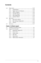
... 2.0 Support 2-29 2.5.4 ACPI APIC Support 2-29 2.5.5 APM Configuration 2-30 2.5.6 Hardware Monitor 2-32 2.6 Boot menu 2-33 2.6.1 Boot Device Priority 2-33 2.6.2 Boot Settings Configuration 2-34 2.6.3 Security 2-35 2.7 Exit menu 2-37 Chapter 3: Software support 3.1 Installing an operating system 3-2 3.2 Support CD information 3-2 3.2.1 Running the support CD 3-2 3.2.2 Drivers menu 3-3 3.2.3 Utilities menu 3-4 3.2.4 Make Disk 3-5 3.2.5 Manual menu 3-6 3.2.6 ASUS Contact...
... 2.0 Support 2-29 2.5.4 ACPI APIC Support 2-29 2.5.5 APM Configuration 2-30 2.5.6 Hardware Monitor 2-32 2.6 Boot menu 2-33 2.6.1 Boot Device Priority 2-33 2.6.2 Boot Settings Configuration 2-34 2.6.3 Security 2-35 2.7 Exit menu 2-37 Chapter 3: Software support 3.1 Installing an operating system 3-2 3.2 Support CD information 3-2 3.2.1 Running the support CD 3-2 3.2.2 Drivers menu 3-3 3.2.3 Utilities menu 3-4 3.2.4 Make Disk 3-5 3.2.5 Manual menu 3-6 3.2.6 ASUS Contact...

Motherboard Installation Guide
Page 8
...package. Where to find more information Refer to the ASUS contact information. 2. These documents are also provided. • Chapter 3: Software support This chapter describes the contents of the motherboard and the new technology it supports. viii Detailed descriptions of the BIOS parameters are not... part of the jumpers and connectors on ASUS hardware and software products. It includes description of the standard package. This ...
...package. Where to find more information Refer to the ASUS contact information. 2. These documents are also provided. • Chapter 3: Software support This chapter describes the contents of the motherboard and the new technology it supports. viii Detailed descriptions of the BIOS parameters are not... part of the jumpers and connectors on ASUS hardware and software products. It includes description of the standard package. This ...
Motherboard Installation Guide
Page 11
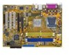
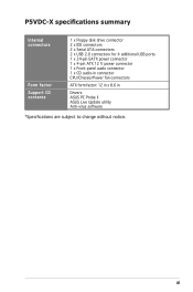
P5VDC-X specifications summary Internal connectors Form factor Support CD contents 1 x Floppy disk drive connector 2 x IDE connectors 2 x Serial ATA connectors 2 x USB 2.0 connectors for 4 additional USB ports 1 x 24-pin EATX power connector 1 x 4-pin ATX 12 V power connector 1 x Front panel audio connector 1 x CD audio-in connector CPU/Chassis/Power fan connectors ATX form factor: 12 in x 8.6 in Drivers ASUS PC Probe II ASUS Live Update utility Anti-virus software *Specifications are subject to change without notice. xi
P5VDC-X specifications summary Internal connectors Form factor Support CD contents 1 x Floppy disk drive connector 2 x IDE connectors 2 x Serial ATA connectors 2 x USB 2.0 connectors for 4 additional USB ports 1 x 24-pin EATX power connector 1 x 4-pin ATX 12 V power connector 1 x Front panel audio connector 1 x CD audio-in connector CPU/Chassis/Power fan connectors ATX form factor: 12 in x 8.6 in Drivers ASUS PC Probe II ASUS Live Update utility Anti-virus software *Specifications are subject to change without notice. xi

Motherboard Installation Guide
Page 13
This chapter describes the motherboard features and the new technologies it supports. 1Product introduction ASUS P5VDC-X 1-1
This chapter describes the motherboard features and the new technologies it supports. 1Product introduction ASUS P5VDC-X 1-1
Motherboard Installation Guide
Page 14
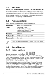
Before you for buying an ASUS® P5VDC-X motherboard! The motherboard also supports the Intel® Hyper-Threading Technology, the Intel® Extended Memory 64 Technology (EM64T) that allows 64-bit computing, and... for the following items. Motherboard ASUS P5VDC-X motherboard Cables 1 x Serial ATA cable 1 x Serial ATA power cable 1 x Ultra DMA 133/100/66 cable 1 x Floppy disk drive cable Accessories I/O shield Application CD ASUS motherboard support CD Documentation User guide If any of ASUS quality motherboards! The motherboard supports the Intel® Pentium®...
Before you for buying an ASUS® P5VDC-X motherboard! The motherboard also supports the Intel® Hyper-Threading Technology, the Intel® Extended Memory 64 Technology (EM64T) that allows 64-bit computing, and... for the following items. Motherboard ASUS P5VDC-X motherboard Cables 1 x Serial ATA cable 1 x Serial ATA power cable 1 x Ultra DMA 133/100/66 cable 1 x Floppy disk drive cable Accessories I/O shield Application CD ASUS motherboard support CD Documentation User guide If any of ASUS quality motherboards! The motherboard supports the Intel® Pentium®...
Motherboard Installation Guide
Page 15
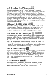
...Intel® 65nm dual-core processors utilize the latest package technologies for more powerful processing. PCI Express™ & AGP8X This motherboard supports PCI Express x16 and AGP8X slots to meet demands for a thinner, lighter design without buying expensive additional LAN cards. Doubled by ...100 Mbps LAN Easy connectivity to 4.3GB/ s. See page 1-22 for details. Intel® 65nm Dual-Core CPU support This motherboard supports Intel® Pentium® D/Pentium® 4/Celeron® dual-core processors built on this motherboard. See page 1-26 for details. ASUS P5VDC-X 1-3
...Intel® 65nm dual-core processors utilize the latest package technologies for more powerful processing. PCI Express™ & AGP8X This motherboard supports PCI Express x16 and AGP8X slots to meet demands for a thinner, lighter design without buying expensive additional LAN cards. Doubled by ...100 Mbps LAN Easy connectivity to 4.3GB/ s. See page 1-22 for details. Intel® 65nm Dual-Core CPU support This motherboard supports Intel® Pentium® D/Pentium® 4/Celeron® dual-core processors built on this motherboard. See page 1-26 for details. ASUS P5VDC-X 1-3
Motherboard Installation Guide
Page 16
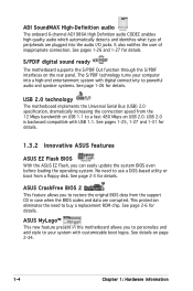
...12 Mbps bandwidth on USB 1.1 to use a DOS-based utility or boot from the support CD in the motherboard allows you can easily update the system BIOS even before loading the operating system. ASUS MyLogo™ This new feature present in case when the BIOS codes and data are ... the original BIOS data from a floppy disk. S/PDIF digital sound ready The motherboard supports the S/PDIF Out function through the S/PDIF interfaces on the rear panel. See pages 1-25, 1-27 and 1-31 for details. ASUS CrashFree BIOS 2 This feature allows you to your computer into the audio I/O jacks.
...12 Mbps bandwidth on USB 1.1 to use a DOS-based utility or boot from the support CD in the motherboard allows you can easily update the system BIOS even before loading the operating system. ASUS MyLogo™ This new feature present in case when the BIOS codes and data are ... the original BIOS data from a floppy disk. S/PDIF digital sound ready The motherboard supports the S/PDIF Out function through the S/PDIF interfaces on the rear panel. See pages 1-25, 1-27 and 1-31 for details. ASUS CrashFree BIOS 2 This feature allows you to your computer into the audio I/O jacks.
Motherboard Installation Guide
Page 22
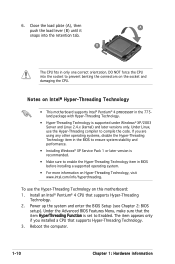
...10 Chapter 1: Hardware information B The CPU fits in the 775land package with Hyper-Threading Technology. • Hyper-Threading Technology is supported under Windows® XP/2003 Server and Linux 2.4.x (kernel) and later versions only. Under Linux, use the Hyper-Threading Technology on... Function is recommended. • Make sure to prevent benting the connectors on Intel® Hyper-Threading Technology • This motherboard supports Intel® Pentium® 4 processor in only one correct orientation. Close the load plate (A), then push the load lever (B)...
...10 Chapter 1: Hardware information B The CPU fits in the 775land package with Hyper-Threading Technology. • Hyper-Threading Technology is supported under Windows® XP/2003 Server and Linux 2.4.x (kernel) and later versions only. Under Linux, use the Hyper-Threading Technology on... Function is recommended. • Make sure to prevent benting the connectors on Intel® Hyper-Threading Technology • This motherboard supports Intel® Pentium® 4 processor in only one correct orientation. Close the load plate (A), then push the load lever (B)...

Motherboard Installation Guide
Page 28
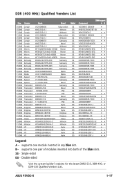
... HYB25D512800BE-5B HYB25D256800CE-5C HYB25D256800CE-5C HYB25D512800BE-5B (Continued on the next page) DIMM support A B 1-16 Chapter 1: Hardware information supports one pair of modules inserted into both of the yellow slots. supports one module inserted in any yellow slot. Single-sided DS - DDR2 (533 MHz)... Qualified Vendors List Size Vendor Mode Brand Side(s) Component DIMM support A B 256MB Kingston KVR533D2N4/256 Elpida SS 256MB Kingston KVR533D2N4/256 Elpida SS 512MB Kingston KVR533D2N4/512 Hynix DS 512MB Kingston ...
... HYB25D512800BE-5B HYB25D256800CE-5C HYB25D256800CE-5C HYB25D512800BE-5B (Continued on the next page) DIMM support A B 1-16 Chapter 1: Hardware information supports one pair of modules inserted into both of the yellow slots. supports one module inserted in any yellow slot. Single-sided DS - DDR2 (533 MHz)... Qualified Vendors List Size Vendor Mode Brand Side(s) Component DIMM support A B 256MB Kingston KVR533D2N4/256 Elpida SS 256MB Kingston KVR533D2N4/256 Elpida SS 512MB Kingston KVR533D2N4/512 Hynix DS 512MB Kingston ...
Motherboard Installation Guide
Page 29
... DS DS SS SS SS SS SS DS DS DS SS DS SS DS SS DS SS SS DS SS DS SS DS Component DIMM support A B VS32M8-5 2B0409 HYB25D256807BT-5B W942508CH-5 VS32M8-5 2B0402 W942508BH-6 K4H560838D-TCB3 V58C2256804SAT6 W942508CH-6 MT46V32M8TG-6TG MT46V32M8TG-6TG MT46V32M8TG-5BG MT46V32M8TG-5BC K4H560838F-TCCC K4H560838F-TCCC... V58C2256804SAT5B K4H560838F-TCCC A2S56D30BTP HY5DU56822CT-J V58C2256804SAT6 HY5DU56822BT-J KDL388P4LA-50 KDL388P4EA-50 VDD9616A8A-5C HYB25D256800CE-5C HYB25D256800CE-6C HY5DU56822DT-D43 HY5DU56822DT-D43 HY5DU56822BT-J HY5DU56822BT-J Legend: A - ASUS P5VDC-X 1-17 B -
... DS DS SS SS SS SS SS DS DS DS SS DS SS DS SS DS SS SS DS SS DS SS DS Component DIMM support A B VS32M8-5 2B0409 HYB25D256807BT-5B W942508CH-5 VS32M8-5 2B0402 W942508BH-6 K4H560838D-TCB3 V58C2256804SAT6 W942508CH-6 MT46V32M8TG-6TG MT46V32M8TG-6TG MT46V32M8TG-5BG MT46V32M8TG-5BC K4H560838F-TCCC K4H560838F-TCCC... V58C2256804SAT5B K4H560838F-TCCC A2S56D30BTP HY5DU56822CT-J V58C2256804SAT6 HY5DU56822BT-J KDL388P4LA-50 KDL388P4EA-50 VDD9616A8A-5C HYB25D256800CE-5C HYB25D256800CE-6C HY5DU56822DT-D43 HY5DU56822DT-D43 HY5DU56822BT-J HY5DU56822BT-J Legend: A - ASUS P5VDC-X 1-17 B -

Motherboard Installation Guide
Page 30
... the power supply before adding or removing DIMMs or other system components. Firmly insert the DIMM into a socket to unlock the DIMM. 1 1 DDR DIMM notch Support the DIMM lightly with extra force. 2. Remove the DIMM from the socket. 1-18 Chapter 1: Hardware information Unlock a DDR1 DIMM socket by pressing the retaining clips...
... the power supply before adding or removing DIMMs or other system components. Firmly insert the DIMM into a socket to unlock the DIMM. 1 1 DDR DIMM notch Support the DIMM lightly with extra force. 2. Remove the DIMM from the socket. 1-18 Chapter 1: Hardware information Unlock a DDR1 DIMM socket by pressing the retaining clips...
Motherboard Installation Guide
Page 31
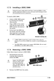
... on the socket such that it flips out 1 with your fingers when pressing the retaining clips. Support the DIMM lightly with extra force. 1 DDR2 DIMM notch 2. 1.7.5 Installing a DDR2 DIMM Unplug the power supply before... inserting or removing DIMMs or other system components. Failure to do not support DDR DIMMs. DO not install DDR DIMMs to the DDR2 DIMM sockets. 1.7.6 Removing a DDR2 DIMM Follow these steps to... the retaining clips snap back in only one direction. ASUS P5VDC-X 1-19 Remove the DIMM from the socket.
... on the socket such that it flips out 1 with your fingers when pressing the retaining clips. Support the DIMM lightly with extra force. 1 DDR2 DIMM notch 2. 1.7.5 Installing a DDR2 DIMM Unplug the power supply before... inserting or removing DIMMs or other system components. Failure to do not support DDR DIMMs. DO not install DDR DIMMs to the DDR2 DIMM sockets. 1.7.6 Removing a DDR2 DIMM Follow these steps to... the retaining clips snap back in only one direction. ASUS P5VDC-X 1-19 Remove the DIMM from the socket.
Motherboard Installation Guide
Page 32
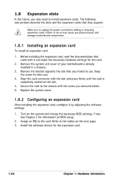
... the card connector with the screw you may cause you intend to install expansion cards. Before installing the expansion card, read the documentation that they support. Refer to the chassis with the slot and press firmly until the card is already installed in a chassis). 3. Turn on the next page. 3. 1.8 Expansion...
... the card connector with the screw you may cause you intend to install expansion cards. Before installing the expansion card, read the documentation that they support. Refer to the chassis with the slot and press firmly until the card is already installed in a chassis). 3. Turn on the next page. 3. 1.8 Expansion...
Motherboard Installation Guide
Page 33
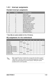
shared - - - - - - - - - - - - shared - - - - - - - - shared - - - - - - ASUS P5VDC-X 1-21 shared shared - - - - - - - - otherwise, conflicts will arise between the two PCI groups, making the system unstable and ...USB 2.0 controller Onboard LAN Onboard audio A B C D E F G H shared - - - - - - - - When using PCI cards on shared slots, ensure that the drivers support "Share IRQ" or that the cards do not need IRQ assignments; shared - - - - - - - - shared - - - - - shared - - - - - - - - IRQ assignments for...
shared - - - - - - - - - - - - shared - - - - - - - - shared - - - - - - ASUS P5VDC-X 1-21 shared shared - - - - - - - - otherwise, conflicts will arise between the two PCI groups, making the system unstable and ...USB 2.0 controller Onboard LAN Onboard audio A B C D E F G H shared - - - - - - - - When using PCI cards on shared slots, ensure that the drivers support "Share IRQ" or that the cards do not need IRQ assignments; shared - - - - - - - - shared - - - - - shared - - - - - - - - IRQ assignments for...
Motherboard Installation Guide
Page 34
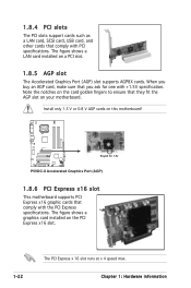
... The figure shows a graphics card installed on a PCI slot. 1.8.5 AGP slot The Accelerated Graphics Port (AGP) slot supports AGP8X cards. Top:Line In Center:Line Out Below:Mic In P5VDC-X R Keyed for one with +1.5V specification. Install only 1.5 V or 0.8 V AGP cards on your motherboard. 1.8.4... buy an AGP card, make sure that comply with PCI specifications. When you ask for 1.5v P5VDC-X Accelerated Graphics Port (AGP) 1.8.6 PCI Express x16 slot This motherboard supports PCI Express x16 graphic cards that they fit the AGP slot on this motherboard!
... The figure shows a graphics card installed on a PCI slot. 1.8.5 AGP slot The Accelerated Graphics Port (AGP) slot supports AGP8X cards. Top:Line In Center:Line Out Below:Mic In P5VDC-X R Keyed for one with +1.5V specification. Install only 1.5 V or 0.8 V AGP cards on your motherboard. 1.8.4... buy an AGP card, make sure that comply with PCI specifications. When you ask for 1.5v P5VDC-X Accelerated Graphics Port (AGP) 1.8.6 PCI Express x16 slot This motherboard supports PCI Express x16 graphic cards that they fit the AGP slot on this motherboard!
Motherboard Installation Guide
Page 41
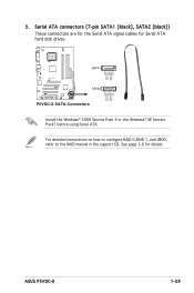
For detailed instructions on how to configure RAID 0,RAID 1, and JBOD, refer to the RAID manual in the support CD. ASUS P5VDC-X 1-29 3. Serial ATA connectors (7-pin SATA1 [black], SATA2 [black]) These connectors are for the Serial ATA signal cables for details. See page ...3-6 for Serial ATA hard disk drives. GND RSATA_TXP1 RSATA_TXN1 GND RSATA_RXP1 RSATA_RXN1 GND Top:Line In Center:Line Out Below:Mic In P5VDC-X R SATA1 SATA2...
For detailed instructions on how to configure RAID 0,RAID 1, and JBOD, refer to the RAID manual in the support CD. ASUS P5VDC-X 1-29 3. Serial ATA connectors (7-pin SATA1 [black], SATA2 [black]) These connectors are for the Serial ATA signal cables for details. See page ...3-6 for Serial ATA hard disk drives. GND RSATA_TXP1 RSATA_TXN1 GND RSATA_RXP1 RSATA_RXN1 GND Top:Line In Center:Line Out Below:Mic In P5VDC-X R SATA1 SATA2...

Motherboard Installation Guide
Page 42
... Connectors 5. Left Audio Channel Ground Ground Right Audio Channel Top:Line In Center:Line Out Below:Mic In P5VDC-X R CD(Black) P5VDC-X Internal Audio Connector 1-30 Chapter 1: Hardware information These are not jumpers! Do not place jumper caps on the motherboard, making sure that ... This connector allows you to the fan connectors. CPU, Chassis and Power Fan connectors (4-pin CPU_FAN, 3-pin CHA_FAN, 3-pin PWR_FAN) The fan connectors support cooling fans of 350mA~740mA (8.88W max.) or a total of the connector. Connect the fan cables to the fan connectors on the fan connectors! Do...
... Connectors 5. Left Audio Channel Ground Ground Right Audio Channel Top:Line In Center:Line Out Below:Mic In P5VDC-X R CD(Black) P5VDC-X Internal Audio Connector 1-30 Chapter 1: Hardware information These are not jumpers! Do not place jumper caps on the motherboard, making sure that ... This connector allows you to the fan connectors. CPU, Chassis and Power Fan connectors (4-pin CPU_FAN, 3-pin CHA_FAN, 3-pin PWR_FAN) The fan connectors support cooling fans of 350mA~740mA (8.88W max.) or a total of the connector. Connect the fan cables to the fan connectors on the fan connectors! Do...
Motherboard Installation Guide
Page 43
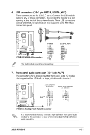
... Line out_L NC Line out_R MIC2_R MIC2_L PORT2 L SENSE_SEND PORT2 R PORT1 R PORT1 L AAFP NC NC NC AGND SENSE2_RETUR SENSE1_RETUR PRESENCE# GND P5VDC-X Analog Front Panel Connector It is recommended that supports up to avail of the system chassis. Front panel audio connector (10-1 pin AAFP) This connector is purchased separately. These USB... to any of these connectors, then install the module to a slot opening at the back of the motherboardʼs high-definition audio capability. ASUS P5VDC-X Analog Front Panel Connector 1-31
... Line out_L NC Line out_R MIC2_R MIC2_L PORT2 L SENSE_SEND PORT2 R PORT1 R PORT1 L AAFP NC NC NC AGND SENSE2_RETUR SENSE1_RETUR PRESENCE# GND P5VDC-X Analog Front Panel Connector It is recommended that supports up to avail of the system chassis. Front panel audio connector (10-1 pin AAFP) This connector is purchased separately. These USB... to any of these connectors, then install the module to a slot opening at the back of the motherboardʼs high-definition audio capability. ASUS P5VDC-X Analog Front Panel Connector 1-31
Motherboard Installation Guide
Page 45
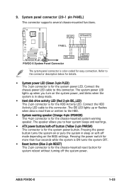
... OFF. • Reset button (Blue 2-pin RESET) This 2-pin connector is for easy connection. System panel connector (20-1 pin PANEL) This connector supports several chassis-mounted functions. The system power LED lights up or flashes when data is read from or written to the HDD. • System... (Yellow 2-pin PWRSW) This connector is for the chassis-mounted system warning speaker. Top:Line In Center:Line Out Below:Mic In P5VDC-X PLED SPEAKER PLED+ PLED+5V Ground Ground Speaker PANEL IDE_LED+ IDE_LED- ASUS P5VDC-X 1-33 Connect the chassis power LED cable to this connector.
... OFF. • Reset button (Blue 2-pin RESET) This 2-pin connector is for easy connection. System panel connector (20-1 pin PANEL) This connector supports several chassis-mounted functions. The system power LED lights up or flashes when data is read from or written to the HDD. • System... (Yellow 2-pin PWRSW) This connector is for the chassis-mounted system warning speaker. Top:Line In Center:Line Out Below:Mic In P5VDC-X PLED SPEAKER PLED+ PLED+5V Ground Ground Speaker PANEL IDE_LED+ IDE_LED- ASUS P5VDC-X 1-33 Connect the chassis power LED cable to this connector.
Motherboard Installation Guide
Page 48
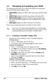
...XP environment a. b. Select the 3 1/2 Floppy Drive icon. A Format 3 1/2 Floppy Disk window appears. b. ASUS EZ Flash (Updates the BIOS using a bootable floppy disk or the motherboard support CD when the BIOS file fails or gets corrupted.) 4. At the DOS prompt, type format A:/S then...in the future. e. c. 2.1 Managing and updating your BIOS The following to the corresponding sections for Windows® 2000: a. ASUS Update (Updates the BIOS in Windows® environment.) Refer to create a bootable floppy disk. Copy the original motherboard BIOS...
...XP environment a. b. Select the 3 1/2 Floppy Drive icon. A Format 3 1/2 Floppy Disk window appears. b. ASUS EZ Flash (Updates the BIOS using a bootable floppy disk or the motherboard support CD when the BIOS file fails or gets corrupted.) 4. At the DOS prompt, type format A:/S then...in the future. e. c. 2.1 Managing and updating your BIOS The following to the corresponding sections for Windows® 2000: a. ASUS Update (Updates the BIOS in Windows® environment.) Refer to create a bootable floppy disk. Copy the original motherboard BIOS...


