Motherboard Installation Guide
Page 27
A B B A B A A B ® CPU fan connector CPU_FAN GND CPU FAN PWR CPU FAN IN CPU FAN PWM 1-13
A B B A B A A B ® CPU fan connector CPU_FAN GND CPU FAN PWR CPU FAN IN CPU FAN PWM 1-13
Motherboard Installation Guide
Page 44
® Fan connectors CPU_FAN GND CPU FAN PWR CPU FAN IN CPU FAN PWM CHA_FAN Rotation +12V GND GND SPDIFOUT +5V SPDIF_OUT ® Digital audio connector 1-30
® Fan connectors CPU_FAN GND CPU FAN PWR CPU FAN IN CPU FAN PWM CHA_FAN Rotation +12V GND GND SPDIFOUT +5V SPDIF_OUT ® Digital audio connector 1-30
Motherboard Installation Guide
Page 70
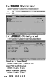
... Menu Item Specific Help Press [Enter] to Thermal [4 Min] Thermal Management TM 1 Limit CPUID MaxVal [Disabled] Execute Disable Bit [Enabled] CPU L1 & L2 Cache [Enabled] Select Menu Item Specific Help DRAM timing and control. F1:Help ESC:Exit :Select Item :Select Item -/+: ...Change Value Enter:Select Submenu F5:Setup Default F10:Save and Exit Advanced Phoenix-Award BIOS Setup Utility CPU Configuration CPU Type Intel Genuine Processor CPU Speed 3.20GHz Cache RAM 1024K Current FSB Frequency 200MHz Delay Prior to set. F1:Help ESC:Exit :Select Item ...
... Menu Item Specific Help Press [Enter] to Thermal [4 Min] Thermal Management TM 1 Limit CPUID MaxVal [Disabled] Execute Disable Bit [Enabled] CPU L1 & L2 Cache [Enabled] Select Menu Item Specific Help DRAM timing and control. F1:Help ESC:Exit :Select Item :Select Item -/+: ...Change Value Enter:Select Submenu F5:Setup Default F10:Save and Exit Advanced Phoenix-Award BIOS Setup Utility CPU Configuration CPU Type Intel Genuine Processor CPU Speed 3.20GHz Cache RAM 1024K Current FSB Frequency 200MHz Delay Prior to set. F1:Help ESC:Exit :Select Item ...
Motherboard Installation Guide
Page 72
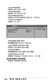
Active to Precharge [07T] Active to CMD (Trcd) [4T] REF to ACT/REF(Trfc) [20T/21T] Act (0) to ACT (1) (TRRD) [3T] Advanced Phoenix-Award BIOS Setup Utility Frequency/Voltage control Select Menu CPU Frequency Ratio Async CPU/PCIE Clock CPU Clock Spread Spectrum [23 X] [Async Mode] [133MHz] [+/-0.2%] Item Specific Help 2-22
Active to Precharge [07T] Active to CMD (Trcd) [4T] REF to ACT/REF(Trfc) [20T/21T] Act (0) to ACT (1) (TRRD) [3T] Advanced Phoenix-Award BIOS Setup Utility Frequency/Voltage control Select Menu CPU Frequency Ratio Async CPU/PCIE Clock CPU Clock Spread Spectrum [23 X] [Async Mode] [133MHz] [+/-0.2%] Item Specific Help 2-22
Motherboard Installation Guide
Page 81
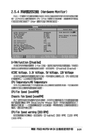
Phoenix-Award BIOS Setup Utility Power Hardware Minitor Select Menu Q-Fan Controller Vcore Voltage 3.3V Voltage 5V Voltage 12V Voltage [Enabled] [1.56V] [3.30V] [5.05V] [11.58V] Item Specific Help Press [Enter] to enable or disable CPU Temperature M/B Temperature CPU Fan Speed Chassis Fan Speed CPU Fan Speed warning Start Up Temperature( ) Full Speed Temperature( ) Start Up PWM Slope PWM 48 41 3068 RPM 0 RPM [800 RPM] [50] [70] [60] [4 PWM/ ] F1:Help ESC:Exit :Select Item :Select Item -/+: Change Value Enter:Select Submenu F5:Setup Default F10:Save and Exit 2-31
Phoenix-Award BIOS Setup Utility Power Hardware Minitor Select Menu Q-Fan Controller Vcore Voltage 3.3V Voltage 5V Voltage 12V Voltage [Enabled] [1.56V] [3.30V] [5.05V] [11.58V] Item Specific Help Press [Enter] to enable or disable CPU Temperature M/B Temperature CPU Fan Speed Chassis Fan Speed CPU Fan Speed warning Start Up Temperature( ) Full Speed Temperature( ) Start Up PWM Slope PWM 48 41 3068 RPM 0 RPM [800 RPM] [50] [70] [60] [4 PWM/ ] F1:Help ESC:Exit :Select Item :Select Item -/+: Change Value Enter:Select Submenu F5:Setup Default F10:Save and Exit 2-31
P5VD2-MX/P5V-VM DH English Edition User's Manual
Page 3
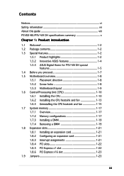
... About this guide viii P5VD2-MX/P5V-VM DH specifications summary x Chapter 1: Product introduction 1.1 Welcome 1-2 1.2 Package contents 1-2 1.3 Special features 1-2 1.3.1 Product highlights 1-2 1.3.2 Innovative ASUS features 1-4 1.3.3 ASUS Digital Home for P5V-VM DH special features 1-5 1.4 Before you proceed 1-7 1.5 Motherboard overview 1-8 1.5.1 Placement direction 1-8 1.5.2 Screw holes 1-8 1.5.3 Motherboard layout 1-9 1.6 Central Processing Unit (CPU 1-10 1.6.1 Installling the CPU 1-10 1.6.2 Installling the CPU heatsink and fan...
... About this guide viii P5VD2-MX/P5V-VM DH specifications summary x Chapter 1: Product introduction 1.1 Welcome 1-2 1.2 Package contents 1-2 1.3 Special features 1-2 1.3.1 Product highlights 1-2 1.3.2 Innovative ASUS features 1-4 1.3.3 ASUS Digital Home for P5V-VM DH special features 1-5 1.4 Before you proceed 1-7 1.5 Motherboard overview 1-8 1.5.1 Placement direction 1-8 1.5.2 Screw holes 1-8 1.5.3 Motherboard layout 1-9 1.6 Central Processing Unit (CPU 1-10 1.6.1 Installling the CPU 1-10 1.6.2 Installling the CPU heatsink and fan...
P5VD2-MX/P5V-VM DH English Edition User's Manual
Page 5
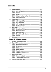
Contents 2.4 Advanced menu 2-20 2.4.1 CPU Configuration 2-20 2.4.2 Chipset 2-21 2.4.3 PCIPnP 2-23 2.4.4 Onboard Devices Configuration 2-24 2.4.5 USB Configuration 2-27 2.5 Power menu 2-28 2.5.1 ACPI Suspend Type 2-... an operating system 3-2 3.2 Support CD information 3-2 3.2.1 Running the support CD 3-2 3.2.2 Drivers menu 3-3 3.2.3 Utilities menu 3-4 3.2.4 Make Disk menu 3-5 3.2.5 Manuals menu 3-5 3.2.6 ASUS Contact information 3-6 3.3 RAID configurations 3-7 3.3.1 Installing hard disks 3-8 3.3.2 JMicron® RAID Configuration 3-12 3.4 Creating a RAID driver disk 3-20 v
Contents 2.4 Advanced menu 2-20 2.4.1 CPU Configuration 2-20 2.4.2 Chipset 2-21 2.4.3 PCIPnP 2-23 2.4.4 Onboard Devices Configuration 2-24 2.4.5 USB Configuration 2-27 2.5 Power menu 2-28 2.5.1 ACPI Suspend Type 2-... an operating system 3-2 3.2 Support CD information 3-2 3.2.1 Running the support CD 3-2 3.2.2 Drivers menu 3-3 3.2.3 Utilities menu 3-4 3.2.4 Make Disk menu 3-5 3.2.5 Manuals menu 3-5 3.2.6 ASUS Contact information 3-6 3.3 RAID configurations 3-7 3.3.1 Installing hard disks 3-8 3.3.2 JMicron® RAID Configuration 3-12 3.4 Creating a RAID driver disk 3-20 v
P5VD2-MX/P5V-VM DH English Edition User's Manual
Page 10
... function Realtek® RTL8201CL 10/100 Mbps LAN Controller Supports up to 64MB shared memory Support max. resolution to 8 USB 2.0 ports ASUS Q-Fan ASUS EZ Flash ASUS CrashFree BIOS 2 MyLogo™ (continued on the next page) x refresh rate to 100Hz (@1600 x 1200) VIA 8237A Southbridge supports...JMicron JMB363 SATA controller cannot be used simultaneously) Integrated Graphics, up to 2048 x 1536 (@75Hz) Support max. P5VD2-MX/P5V-VM DH specifications summary CPU Chipset Front Side Bus Memory Expansion slots VGA Storage Audio LAN USB Special features LGA775 socket for Intel® Core...
... function Realtek® RTL8201CL 10/100 Mbps LAN Controller Supports up to 64MB shared memory Support max. resolution to 8 USB 2.0 ports ASUS Q-Fan ASUS EZ Flash ASUS CrashFree BIOS 2 MyLogo™ (continued on the next page) x refresh rate to 100Hz (@1600 x 1200) VIA 8237A Southbridge supports...JMicron JMB363 SATA controller cannot be used simultaneously) Integrated Graphics, up to 2048 x 1536 (@75Hz) Support max. P5VD2-MX/P5V-VM DH specifications summary CPU Chipset Front Side Bus Memory Expansion slots VGA Storage Audio LAN USB Special features LGA775 socket for Intel® Core...
P5VD2-MX/P5V-VM DH English Edition User's Manual
Page 11
... audio connector 1 x S/PDIF out connector Chassis intrusion System panel connector ATX from 133MHz up to 300MHz at 1MHz increment Adjustable FSB/DDR ratio. P5VD2-MX/P5V-VM DH specifications summary Overclocking Features Rear panel BIOS features Manageability Internal connectors Form Factor Support CD contents ASUS C.P.R. (CPU Parameter Recall) SFS (Stepless Frequency Selection) from factor: 9.6 in...
... audio connector 1 x S/PDIF out connector Chassis intrusion System panel connector ATX from 133MHz up to 300MHz at 1MHz increment Adjustable FSB/DDR ratio. P5VD2-MX/P5V-VM DH specifications summary Overclocking Features Rear panel BIOS features Manageability Internal connectors Form Factor Support CD contents ASUS C.P.R. (CPU Parameter Recall) SFS (Stepless Frequency Selection) from factor: 9.6 in...
P5VD2-MX/P5V-VM DH English Edition User's Manual
Page 15
...CPU cores with JMicron JMB363 SATA controller supports the next-generation hard drives based on external devices. PCI Express features point-to meet demands for a thinner, lighter design without compromising performance. The external SATA port located at the back I /O interconnect technology that speeds up the PCI bus. ASUS P5VD2-MX...plug functions. This motherboard supports the latest Intel® Core™2 processors in LGA775 package. This motherboard also supports Intel® next generation Core™2 Duo CPU. Serial ATA 3Gb/s technology The motherboard built with dedicated...
...CPU cores with JMicron JMB363 SATA controller supports the next-generation hard drives based on external devices. PCI Express features point-to meet demands for a thinner, lighter design without compromising performance. The external SATA port located at the back I /O interconnect technology that speeds up the PCI bus. ASUS P5VD2-MX...plug functions. This motherboard supports the latest Intel® Core™2 processors in LGA775 package. This motherboard also supports Intel® next generation Core™2 Duo CPU. Serial ATA 3Gb/s technology The motherboard built with dedicated...
P5VD2-MX/P5V-VM DH English Edition User's Manual
Page 17
ASUS P5VD2-MX/P5V-VM DH 1-5 C.P.R. (CPU Parameter Recall) The C.P.R. The ASUS WiFi-AP Solo can provide these functions even when the PC is an on-board feature, which means that users will be able to play ... the system hangs due to open the system chassis and clear the RTC data. See page 2-6 for P5V-VM DH) The ASUS WiFi-AP Solo allows a new level of the motherboard BIOS allows automatic re-setting to the BIOS default settings in sleep mode, so users can easily update the system BIOS...
ASUS P5VD2-MX/P5V-VM DH 1-5 C.P.R. (CPU Parameter Recall) The C.P.R. The ASUS WiFi-AP Solo can provide these functions even when the PC is an on-board feature, which means that users will be able to play ... the system hangs due to open the system chassis and clear the RTC data. See page 2-6 for P5V-VM DH) The ASUS WiFi-AP Solo allows a new level of the motherboard BIOS allows automatic re-setting to the BIOS default settings in sleep mode, so users can easily update the system BIOS...
P5VD2-MX/P5V-VM DH English Edition User's Manual
Page 22
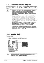
... Return Merchandise Authorization (RMA) requests only if the motherboard comes with installation instructions for the CPU, fan and heatsink assembly. ASUS will shoulder the cost of repair only if the damage is on the socket and the socket pins are not bent. If the instructions... sure that the PnP cap is shipment/ transit-related. • Keep the cap after installing the motherboard. Locate the CPU socket on the motherboard. ® CPU Socket 775 Before installing the CPU, make sure that the socket box is facing towards you and the load lever is on your retailer immediately if the...
... Return Merchandise Authorization (RMA) requests only if the motherboard comes with installation instructions for the CPU, fan and heatsink assembly. ASUS will shoulder the cost of repair only if the damage is on the socket and the socket pins are not bent. If the instructions... sure that the PnP cap is shipment/ transit-related. • Keep the cap after installing the motherboard. Locate the CPU socket on the motherboard. ® CPU Socket 775 Before installing the CPU, make sure that the socket box is facing towards you and the load lever is on your retailer immediately if the...
P5VD2-MX/P5V-VM DH English Edition User's Manual
Page 23
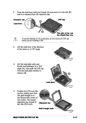
... bottom-left (B) until it to the socket pins, do not remove the PnP cap unless you . The socket alignment key should face you are installing a CPU. 3. Press the load lever with your thumb (A) and move it is released from the load plate window to a 135º angle. 4. Retention tab A ... plate with your thumb and forefinger to a 100º angle (A), then push the PnP cap B from the retention tab. Load plate 5. Gold triangle mark ASUS P5VD2-MX/P5V-VM DH A 1-11 2. To prevent damage to the left corner of the cam box should fit A l i g n m e n t k e y into the...
... bottom-left (B) until it to the socket pins, do not remove the PnP cap unless you . The socket alignment key should face you are installing a CPU. 3. Press the load lever with your thumb (A) and move it is released from the load plate window to a 135º angle. 4. Retention tab A ... plate with your thumb and forefinger to a 100º angle (A), then push the PnP cap B from the retention tab. Load plate 5. Gold triangle mark ASUS P5VD2-MX/P5V-VM DH A 1-11 2. To prevent damage to the left corner of the cam box should fit A l i g n m e n t k e y into the...
P5VD2-MX/P5V-VM DH English Edition User's Manual
Page 24
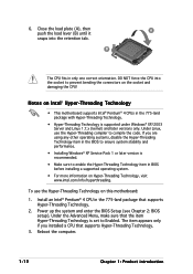
...to prevent bending the connectors on this motherboard: 1. Reboot the computer. 1-12 Chapter 1: Product introduction Power up the system and enter the BIOS Setup (see Chapter 2: BIOS setup). Install an Intel® Pentium® 4 CPU in the 775-land package that supports... more information on Intel® Hyper-Threading Technology • This motherboard supports Intel® Pentium® 4 CPUs in only one correct orientation. If you installed a CPU that supports Hyper-Threading Technology. 2. B The CPU fits in the 775-land package with Hyper-Threading Technology. •...
...to prevent bending the connectors on this motherboard: 1. Reboot the computer. 1-12 Chapter 1: Product introduction Power up the system and enter the BIOS Setup (see Chapter 2: BIOS setup). Install an Intel® Pentium® 4 CPU in the 775-land package that supports... more information on Intel® Hyper-Threading Technology • This motherboard supports Intel® Pentium® 4 CPUs in only one correct orientation. If you installed a CPU that supports Hyper-Threading Technology. 2. B The CPU fits in the 775-land package with Hyper-Threading Technology. •...
P5VD2-MX/P5V-VM DH English Edition User's Manual
Page 25
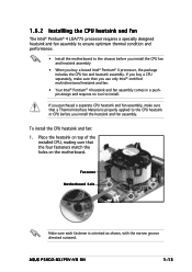
... heatsink and fan assembly. Fastener Motherboard hole Make sure each fastener is properly applied to the CPU heatsink or CPU before you install the CPU fan and heatsink assembly • When you buy a CPU separately, make sure that a Thermal Interface Material is oriented as shown, with the narrow groove directed outward. ASUS P5VD2-MX/P5V-VM DH 1-13...
... heatsink and fan assembly. Fastener Motherboard hole Make sure each fastener is properly applied to the CPU heatsink or CPU before you install the CPU fan and heatsink assembly • When you buy a CPU separately, make sure that a Thermal Interface Material is oriented as shown, with the narrow groove directed outward. ASUS P5VD2-MX/P5V-VM DH 1-13...
P5VD2-MX/P5V-VM DH English Edition User's Manual
Page 26
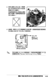
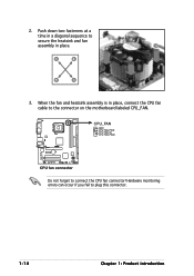
When the fan and heatsink assembly is in place, connect the CPU fan cable to connect the CPU fan connector! 2. A A A B B B A 3. CPU_FAN GND CPU FAN PWR CPU FAN IN CPU FAN PWM ® CPU fan connector Do not forget to the connector on the motherboard labeled CPU_FAN. Push down two fasteners at a time in place. Hardware monitoring errors can occur if you fail to secure the heatsink and fan B assembly in a diagonal sequence to plug this connector. 1-14 Chapter 1: Product introduction
When the fan and heatsink assembly is in place, connect the CPU fan cable to connect the CPU fan connector! 2. A A A B B B A 3. CPU_FAN GND CPU FAN PWR CPU FAN IN CPU FAN PWM ® CPU fan connector Do not forget to the connector on the motherboard labeled CPU_FAN. Push down two fasteners at a time in place. Hardware monitoring errors can occur if you fail to secure the heatsink and fan B assembly in a diagonal sequence to plug this connector. 1-14 Chapter 1: Product introduction
P5VD2-MX/P5V-VM DH English Edition User's Manual
Page 27
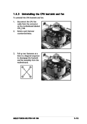
Disconnect the CPU fan cable from the A A motherboard. Pull up two fasteners at a time in a diagonal sequence to disengage the heatsink B and fan assembly from the connector on the motherboard labeled CPU_FAN. 2. B A B B A ASUS P5VD2-MX/P5V-VM DH 1-15 1.6.3 Uninstalling the CPU heatsink and fan To uninstall the CPU heatsink and fan: 1. Rotate each fastener counterclockwise. 3.
Disconnect the CPU fan cable from the A A motherboard. Pull up two fasteners at a time in a diagonal sequence to disengage the heatsink B and fan assembly from the connector on the motherboard labeled CPU_FAN. 2. B A B B A ASUS P5VD2-MX/P5V-VM DH 1-15 1.6.3 Uninstalling the CPU heatsink and fan To uninstall the CPU heatsink and fan: 1. Rotate each fastener counterclockwise. 3.
P5VD2-MX/P5V-VM DH English Edition User's Manual
Page 35
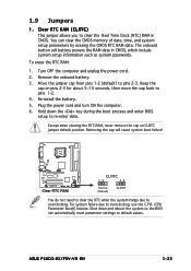
..., and system setup parameters by erasing the CMOS RTC RAM data. Shut down the key during the boot process and enter BIOS setup to pins 2-3. ASUS P5VD2-MX/P5V-VM DH 1-23 Remove the onboard battery. 3. Move the jumper cap from pins 1-2 (default) to re-enter data. The onboard button cell ...RTC RAM CLRTC 12 23 Normal (Default) CLEAR You do not need to clear the RTC when the system hangs due to overclocking, use the C.P.R. (CPU Parameter Recall) feature. Except when clearing the RTC RAM, never remove the cap on pins 2-3 for about 5~10 seconds, then move the cap back...
..., and system setup parameters by erasing the CMOS RTC RAM data. Shut down the key during the boot process and enter BIOS setup to pins 2-3. ASUS P5VD2-MX/P5V-VM DH 1-23 Remove the onboard battery. 3. Move the jumper cap from pins 1-2 (default) to re-enter data. The onboard button cell ...RTC RAM CLRTC 12 23 Normal (Default) CLEAR You do not need to clear the RTC when the system hangs due to overclocking, use the C.P.R. (CPU Parameter Recall) feature. Except when clearing the RTC RAM, never remove the cap on pins 2-3 for about 5~10 seconds, then move the cap back...
P5VD2-MX/P5V-VM DH English Edition User's Manual
Page 36
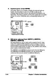
2. This feature requires an ATX power supply that you can supply at least 1A on the keyboard...jumper is the Space Bar). Set this jumper to pins 2-3 (+5VSB) to wake up the computer when you to CPU, DRAM in slow refresh, power supply in low power mode) using the connected USB devices. USB device wake-up (3-... or disable the keyboard wake-up +5V +5VSB 1-24 Chapter 1: Product introduction Set to +5VSB to wake up from S1 sleep mode (CPU stopped, DRAM refreshed, system running in reduced power mode). KBPWR 12 23 +5V (Default) +5VSB ® Keyboard power setting 3 . ...
2. This feature requires an ATX power supply that you can supply at least 1A on the keyboard...jumper is the Space Bar). Set this jumper to pins 2-3 (+5VSB) to wake up the computer when you to CPU, DRAM in slow refresh, power supply in low power mode) using the connected USB devices. USB device wake-up (3-... or disable the keyboard wake-up +5V +5VSB 1-24 Chapter 1: Product introduction Set to +5VSB to wake up from S1 sleep mode (CPU stopped, DRAM refreshed, system running in reduced power mode). KBPWR 12 23 +5V (Default) +5VSB ® Keyboard power setting 3 . ...

P5VD2-MX/P5V-VM DH English Edition User's Manual
Page 43
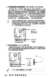
...the motherboard, making sure that the black wire of each cable matches the ground pin of the S/PDIF audio cable to this connector and the other end to the S/PDIF module. CPU_FAN GND CPU FAN PWR CPU FAN IN CPU FAN PWM ® Fan connectors CHA_FAN Rotation +12V GND 6 . ASUS P5VD2-MX/...P5V-VM DH GND SPDIFOUT +5V 1-31 Connect the fan cables to the fan connectors on the fan connectors. 5. CPU and Chassis fan connectors (4-pin CPU_FAN, 3-pin...
...the motherboard, making sure that the black wire of each cable matches the ground pin of the S/PDIF audio cable to this connector and the other end to the S/PDIF module. CPU_FAN GND CPU FAN PWR CPU FAN IN CPU FAN PWM ® Fan connectors CHA_FAN Rotation +12V GND 6 . ASUS P5VD2-MX/...P5V-VM DH GND SPDIFOUT +5V 1-31 Connect the fan cables to the fan connectors on the fan connectors. 5. CPU and Chassis fan connectors (4-pin CPU_FAN, 3-pin...


