Motherboard Installation Guide
Page 1
P5SD2-X SE Motherboard
P5SD2-X SE Motherboard

Motherboard Installation Guide
Page 3
Contents Notices vi Safety information vii About this guide viii Typography ix P5SD2-X SE specifications summary x Chapter 1: Product introduction 1.1 Welcome 1-2 1.2 Package contents 1-2 1.3 Special features 1-2 1.3.1 Product highlights 1-2 1.3.2 Innovative ASUS features 1-4 1.4 Before you proceed 1-5 1.5 Motherboard overview 1-6 1.5.1 Placement direction 1-6 1.5.2 Screw holes 1-6 1.5.3 Motherboard layout 1-7 1.6 Central Processing Unit (CPU 1-8 1.6.1 Installling the CPU 1-8 1.6.2 Installling the CPU heatsink and fan 1-11...
Contents Notices vi Safety information vii About this guide viii Typography ix P5SD2-X SE specifications summary x Chapter 1: Product introduction 1.1 Welcome 1-2 1.2 Package contents 1-2 1.3 Special features 1-2 1.3.1 Product highlights 1-2 1.3.2 Innovative ASUS features 1-4 1.4 Before you proceed 1-5 1.5 Motherboard overview 1-6 1.5.1 Placement direction 1-6 1.5.2 Screw holes 1-6 1.5.3 Motherboard layout 1-7 1.6 Central Processing Unit (CPU 1-8 1.6.1 Installling the CPU 1-8 1.6.2 Installling the CPU heatsink and fan 1-11...

Motherboard Installation Guide
Page 7
Operation safety • Before installing the motherboard and adding devices on a stable surface. • If you are using, contact your area. These devices could interrupt the grounding circuit. • Make sure that ..., contact your retailer. Contact a qualified service technician or your dealer immediately. • To avoid short circuits, keep paper clips, screws, and staples away from the motherboard, ensure that came with the product, contact a qualified service technician or your power supply is broken, do not try to fix it , carefully read all...
Operation safety • Before installing the motherboard and adding devices on a stable surface. • If you are using, contact your area. These devices could interrupt the grounding circuit. • Make sure that ..., contact your retailer. Contact a qualified service technician or your dealer immediately. • To avoid short circuits, keep paper clips, screws, and staples away from the motherboard, ensure that came with the product, contact a qualified service technician or your power supply is broken, do not try to fix it , carefully read all...
Motherboard Installation Guide
Page 8
...motherboard and the new technology it supports. ASUS websites The ASUS website provides updated information on the motherboard. • Chapter 2: BIOS setup This chapter tells how to the following parts: • Chapter 1: Product introduction This chapter describes the features of the jumpers and connectors on ASUS... part of the support CD that may include optional documentation, such as warranty flyers, that comes with the motherboard package. About this guide is organized This manual contains the following sources for additional information and for product and software ...
...motherboard and the new technology it supports. ASUS websites The ASUS website provides updated information on the motherboard. • Chapter 2: BIOS setup This chapter tells how to the following parts: • Chapter 1: Product introduction This chapter describes the features of the jumpers and connectors on ASUS... part of the support CD that may include optional documentation, such as warranty flyers, that comes with the motherboard package. About this guide is organized This manual contains the following sources for additional information and for product and software ...
Motherboard Installation Guide
Page 13
This chapter describes the motherboard features and the new technologies it supports. 1Product introduction ASUS P5SD2-X SE 1-1
This chapter describes the motherboard features and the new technologies it supports. 1Product introduction ASUS P5SD2-X SE 1-1
Motherboard Installation Guide
Page 14
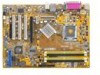
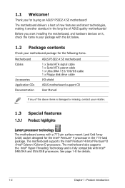
1.1 Welcome! Before you for the following items. Motherboard Cables Accessories Application CDs Documentation ASUS P5SD2-X SE motherboard 1 x Serial ATA signal cable 1 x Serial ATA power cable 1 x Ultra DMA 133/100/66 cable 1 x Floppy disk drive cable I/O shield ASUS motherboard support CD User Manual If any of ASUS quality motherboards! The motherboard supports the Intel® Pentium® 4/Intel® Pentium® D /Intel...
1.1 Welcome! Before you for the following items. Motherboard Cables Accessories Application CDs Documentation ASUS P5SD2-X SE motherboard 1 x Serial ATA signal cable 1 x Serial ATA power cable 1 x Ultra DMA 133/100/66 cable 1 x Floppy disk drive cable I/O shield ASUS motherboard support CD User Manual If any of ASUS quality motherboards! The motherboard supports the Intel® Pentium® 4/Intel® Pentium® D /Intel...
Motherboard Installation Guide
Page 15
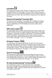
...™ Interface The motherboard fully supports PCI Express, the latest I/O interconnect technology that smartly manages data streaming between devices and allows higher clockspeeds by automatically adjusting the CPU voltage and core frequency depending on 64-bit operating systems and access larger amounts of your computer to 10.7 GB/s. ASUS P5SD2-X SE 1-3 PCI Express features...
...™ Interface The motherboard fully supports PCI Express, the latest I/O interconnect technology that smartly manages data streaming between devices and allows higher clockspeeds by automatically adjusting the CPU voltage and core frequency depending on 64-bit operating systems and access larger amounts of your computer to 10.7 GB/s. ASUS P5SD2-X SE 1-3 PCI Express features...
Motherboard Installation Guide
Page 16
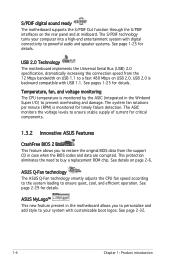
... connectivity to ensure quiet, cool, and efficient operation. See page 2-32. 1-4 Chapter 1: Product introduction S/PDIF digital sound ready The motherboard supports the S/PDIF Out function through the S/PDIF interfaces on the rear panel and at midboard. USB 2.0 is monitored by the ASIC (integrated... in case when the BIOS codes and data are corrupted. ASUS MyLogo™ This new feature present in the motherboard allows you to restore the original BIOS data from the 12 Mbps bandwidth on USB 1.1 to prevent overheating and ...
... connectivity to ensure quiet, cool, and efficient operation. See page 2-32. 1-4 Chapter 1: Product introduction S/PDIF digital sound ready The motherboard supports the S/PDIF Out function through the S/PDIF interfaces on the rear panel and at midboard. USB 2.0 is monitored by the ASIC (integrated... in case when the BIOS codes and data are corrupted. ASUS MyLogo™ This new feature present in the motherboard allows you to restore the original BIOS data from the 12 Mbps bandwidth on USB 1.1 to prevent overheating and ...
Motherboard Installation Guide
Page 17
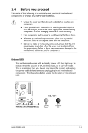
...ON, in sleep mode, or in soft-off mode. The illustration below shows the location of the following precautions before you install motherboard components or change any motherboard settings. • Unplug the power cord from the power supply. 1.4 Before you proceed Take note of the onboard LED. Onboard... supply case, before handling components to avoid damaging them due to static electricity • Hold components by the edges to the motherboard, peripherals, and/or components. P5SD2-X SE ® P5SD2-X SE Onboard LED SB_PWR ON Standby Power OFF Powered Off ASUS P5SD2-X SE 1-5
...ON, in sleep mode, or in soft-off mode. The illustration below shows the location of the following precautions before you install motherboard components or change any motherboard settings. • Unplug the power cord from the power supply. 1.4 Before you proceed Take note of the onboard LED. Onboard... supply case, before handling components to avoid damaging them due to static electricity • Hold components by the edges to the motherboard, peripherals, and/or components. P5SD2-X SE ® P5SD2-X SE Onboard LED SB_PWR ON Standby Power OFF Powered Off ASUS P5SD2-X SE 1-5

Motherboard Installation Guide
Page 18
Do not overtighten the screws! Failure to do so can damage the motherboard. Place this side towards the rear of the chassis P5SD2-X SE ® 1-6 Chapter 1: Product introduction Doing so can cause you place it . The edge with external ports goes to the rear part... of the chassis as indicated in the correct orientation. Make sure to unplug the power cord before installing or removing the motherboard. 1.5 Motherboard overview ...
Do not overtighten the screws! Failure to do so can damage the motherboard. Place this side towards the rear of the chassis P5SD2-X SE ® 1-6 Chapter 1: Product introduction Doing so can cause you place it . The edge with external ports goes to the rear part... of the chassis as indicated in the correct orientation. Make sure to unplug the power cord before installing or removing the motherboard. 1.5 Motherboard overview ...

Motherboard Installation Guide
Page 20
...P5SD2-X SE ® P5SD2-X SE CPU Socket 775 Before installing the CPU, make sure that the socket box is facing towards you see any damage to the socket pins resulting from incorrect CPU installation/removal, or misplacement/ loss/incorrect removal of the PnP cap. 1.6.1 Installing the CPU To install a CPU: 1. ASUS...missing, or if you and the load lever is on your left. 1-8 Chapter 1: Product introduction 1.6 Central Processing Unit (CPU) The motherboard comes with a surface mount LGA775 socket designed for the Intel® Pentium® 4 processor in this section do not match the CPU ...
...P5SD2-X SE ® P5SD2-X SE CPU Socket 775 Before installing the CPU, make sure that the socket box is facing towards you see any damage to the socket pins resulting from incorrect CPU installation/removal, or misplacement/ loss/incorrect removal of the PnP cap. 1.6.1 Installing the CPU To install a CPU: 1. ASUS...missing, or if you and the load lever is on your left. 1-8 Chapter 1: Product introduction 1.6 Central Processing Unit (CPU) The motherboard comes with a surface mount LGA775 socket designed for the Intel® Pentium® 4 processor in this section do not match the CPU ...
Motherboard Installation Guide
Page 22
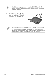
B The motherboard supports Intel® Pentium® 4 LGA775 processors with the Intel® Enhanced Memory 64 Technology (EM64T), Enhanced Intel SpeedStep® Technology (EIST), and Hyper-Threading Technology. Refer to prevent bending the connectors on these CPU features. 1-10 Chapter 1: Product introduction DO NOT force the CPU into the retention tab. Close the load plate (A), then A push the load lever (B) until it snaps into the socket to the Appendix for more information on the socket and damaging the CPU! 6. The CPU fits in only one correct orientation.
B The motherboard supports Intel® Pentium® 4 LGA775 processors with the Intel® Enhanced Memory 64 Technology (EM64T), Enhanced Intel SpeedStep® Technology (EIST), and Hyper-Threading Technology. Refer to prevent bending the connectors on these CPU features. 1-10 Chapter 1: Product introduction DO NOT force the CPU into the retention tab. Close the load plate (A), then A push the load lever (B) until it snaps into the socket to the Appendix for more information on the socket and damaging the CPU! 6. The CPU fits in only one correct orientation.
Motherboard Installation Guide
Page 23
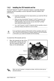
... heatsink and fan assembly, make sure that the four fasteners match the holes on the motherboard. Fastener Motherboard hole Make sure each fastener is properly applied to the chassis before you install the heatsink and fan assembly. ASUS P5SD2-X SE 1-11 1.6.2 Installing the CPU heatsink and fan The Intel® Pentium® 4 LGA775 processor requires...
... heatsink and fan assembly, make sure that the four fasteners match the holes on the motherboard. Fastener Motherboard hole Make sure each fastener is properly applied to the chassis before you install the heatsink and fan assembly. ASUS P5SD2-X SE 1-11 1.6.2 Installing the CPU heatsink and fan The Intel® Pentium® 4 LGA775 processor requires...

Motherboard Installation Guide
Page 24
Hardware monitoring errors can occur if you fail to connect the CPU fan connector! When the fan and heatsink assembly is in place. Push down two fasteners at a time in a diagonal sequence to secure the heatsink and fan assembly in place, connect the CPU fan cable to the connector on the motherboard labeled CPU_FAN. B A B A A B B A 3. P5SD2-X SE CPU_FAN GND CPU FAN PWR CPU FAN IN CPU FAN PWM ® P5SD2-X SE CPU Fan Connector Do not forget to plug this connector. 1-12 Chapter 1: Product introduction 2.
Hardware monitoring errors can occur if you fail to connect the CPU fan connector! When the fan and heatsink assembly is in place. Push down two fasteners at a time in a diagonal sequence to secure the heatsink and fan assembly in place, connect the CPU fan cable to the connector on the motherboard labeled CPU_FAN. B A B A A B B A 3. P5SD2-X SE CPU_FAN GND CPU FAN PWR CPU FAN IN CPU FAN PWM ® P5SD2-X SE CPU Fan Connector Do not forget to plug this connector. 1-12 Chapter 1: Product introduction 2.
Motherboard Installation Guide
Page 25
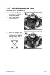
Disconnect the CPU fan cable from the A A motherboard. 1.6.3 Uninstalling the CPU heatsink and fan To uninstall the CPU heatsink and fan: 1. B A B B A ASUS P5SD2-X SE 1-13 Rotate each fastener counterclockwise. 3. Pull up two fasteners at a time in a diagonal sequence B to disengage the heatsink and fan assembly from the connector on the motherboard. 2.
Disconnect the CPU fan cable from the A A motherboard. 1.6.3 Uninstalling the CPU heatsink and fan To uninstall the CPU heatsink and fan: 1. B A B B A ASUS P5SD2-X SE 1-13 Rotate each fastener counterclockwise. 3. Pull up two fasteners at a time in a diagonal sequence B to disengage the heatsink and fan assembly from the connector on the motherboard. 2.

Motherboard Installation Guide
Page 26
When reset, each fastener clockwise to reset the orientation. Rotate each fastener should be oriented as shown, with the narrow groove directed outward. 1-14 Chapter 1: Product introduction Remove the heatsink and fan assembly from the motherboard. 5. 4.
When reset, each fastener clockwise to reset the orientation. Rotate each fastener should be oriented as shown, with the narrow groove directed outward. 1-14 Chapter 1: Product introduction Remove the heatsink and fan assembly from the motherboard. 5. 4.
Motherboard Installation Guide
Page 27
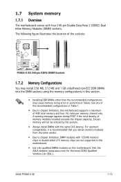
...of the recommended configurations in this motherboard. ASUS P5SD2-X SE 1-15 A warning message appears during POST if the total density of 4GB total memory and four (4) ranks per memory channel only. Visit the ASUS website (www.asus.com) for the latest DDR2 Qualified...) Dual Inline Memory Modules (DIMM) sockets. 1.7 System memory 1.7.1 Overview The motherboard comes with the same CAS latency. Use any of the sockets: P5SD2-X SE DIMM_A1 DIMM_A2 DIMM_B1 DIMM_B2 ® P5SD2-X SE 240-pin DDR2 DIMM Sockets 1.7.2 Memory Configurations You may cause memory sizing...
...of the recommended configurations in this motherboard. ASUS P5SD2-X SE 1-15 A warning message appears during POST if the total density of 4GB total memory and four (4) ranks per memory channel only. Visit the ASUS website (www.asus.com) for the latest DDR2 Qualified...) Dual Inline Memory Modules (DIMM) sockets. 1.7 System memory 1.7.1 Overview The motherboard comes with the same CAS latency. Use any of the sockets: P5SD2-X SE DIMM_A1 DIMM_A2 DIMM_B1 DIMM_B2 ® P5SD2-X SE 240-pin DDR2 DIMM Sockets 1.7.2 Memory Configurations You may cause memory sizing...

Motherboard Installation Guide
Page 30
...: 1. Firmly insert the DIMM into a socket to avoid damaging the DIMM. • The DDR2 DIMM sockets do so can cause severe damage to both the motherboard and the components. Failure to do not support DDR DIMMs. DO not install DDR DIMMs to the DDR2 DIMM sockets. 1.7.4 Removing a DIMM Follow these steps...
...: 1. Firmly insert the DIMM into a socket to avoid damaging the DIMM. • The DDR2 DIMM sockets do so can cause severe damage to both the motherboard and the components. Failure to do not support DDR DIMMs. DO not install DDR DIMMs to the DDR2 DIMM sockets. 1.7.4 Removing a DIMM Follow these steps...
Motherboard Installation Guide
Page 31
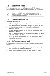
... Installing an expansion card To install an expansion card: 1. Make sure to install expansion cards. Remove the system unit cover (if your motherboard is completely seated on the system and change the necessary BIOS settings, if any. Replace the system cover. 1.8.2 Configuring an ...card, configure it and make the necessary hardware settings for later use . Assign an IRQ to the tables on BIOS setup. 2. ASUS P5SD2-X SE 1-19 Refer to the card. The following sub-sections describe the slots and the expansion cards that you removed earlier. 6. Before installing the ...
... Installing an expansion card To install an expansion card: 1. Make sure to install expansion cards. Remove the system unit cover (if your motherboard is completely seated on the system and change the necessary BIOS settings, if any. Replace the system cover. 1.8.2 Configuring an ...card, configure it and make the necessary hardware settings for later use . Assign an IRQ to the tables on BIOS setup. 2. ASUS P5SD2-X SE 1-19 Refer to the card. The following sub-sections describe the slots and the expansion cards that you removed earlier. 6. Before installing the ...
Motherboard Installation Guide
Page 32
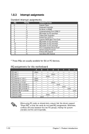
...* IRQ holder for PCI steering* PS/2 Compatible Mouse Port* Numeric Data Processor Primary IDE Channel Secondary IDE Channel * These IRQs are usually available for this motherboard A B C D E PCI slot 1 PCI slot 2 PCI slot 3 PCI Express x1 slot 1 PCI Express x1 slot 2 PCI Express x16 slot Onboard USB controller 1 Onboard USB controller 2 Onboard...
...* IRQ holder for PCI steering* PS/2 Compatible Mouse Port* Numeric Data Processor Primary IDE Channel Secondary IDE Channel * These IRQs are usually available for this motherboard A B C D E PCI slot 1 PCI slot 2 PCI slot 3 PCI Express x1 slot 1 PCI Express x1 slot 2 PCI Express x16 slot Onboard USB controller 1 Onboard USB controller 2 Onboard...


