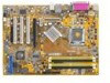
Motherboard Installation Guide
Page 13
This chapter describes the motherboard features and the new technologies it supports. 1Product introduction ASUS P5SD2-X SE 1-1
Motherboard Installation Guide
Page 14
... missing, contact your motherboard package for the following items. Motherboard Cables Accessories Application CDs Documentation ASUS P5SD2-X SE motherboard 1 x Serial ATA signal cable 1 x Serial ATA power cable 1 x Ultra DMA 133/100/66 cable 1 x Floppy disk drive cable I/O shield ASUS motherboard support CD User Manual If any of the above items is fully compatible with...
Motherboard Installation Guide
Page 15
... high speed interface is software compatible with the Intel® EM64T (Extended Memory 64 Technology). See page 1-27 for efficient and superior performance. ASUS P5SD2-X SE 1-3 PCI Express™ Interface The motherboard fully supports PCI Express, the latest I/O interconnect technology that smartly manages data streaming between devices and allows higher clockspeeds...
Motherboard Installation Guide
Page 17
... as the power supply case, before removing or plugging in soft-off or the power cord is switched off mode. P5SD2-X SE ® P5SD2-X SE Onboard LED SB_PWR ON Standby Power OFF Powered Off ASUS P5SD2-X SE 1-5 The illustration below shows the location of the following precautions before you install motherboard components or change any motherboard settings...
Motherboard Installation Guide
Page 21
... the load plate with your thumb and forefinger to the socket pins, do not remove the PnP cap unless you . Gold triangle mark ASUS P5SD2-X SE A 1-9 Lift the load lever in the direction of the socket. To prevent damage to a 100º angle (A), then push the PnP cap B from the retention...
Motherboard Installation Guide
Page 23
.... If you purchased a separate CPU heatsink and fan assembly, make sure that a Thermal Interface Material is oriented as shown, with the narrow groove directed outward. ASUS P5SD2-X SE 1-11 To install the CPU heatsink and fan: 1. If you buy a boxed Intel® Pentium® 4 LGA775 processor, the package includes the CPU fan and...
Motherboard Installation Guide
Page 25
Pull up two fasteners at a time in a diagonal sequence B to disengage the heatsink and fan assembly from the connector on the motherboard. 2. Disconnect the CPU fan cable from the A A motherboard. B A B B A ASUS P5SD2-X SE 1-13 1.6.3 Uninstalling the CPU heatsink and fan To uninstall the CPU heatsink and fan: 1. Rotate each fastener counterclockwise. 3.
Motherboard Installation Guide
Page 27
...Modules (DIMM) sockets. The following figure illustrates the location of 4GB total memory and four (4) ranks per memory channel only. ASUS P5SD2-X SE 1-15 A warning message appears during POST if the total density of memory modules installed exceeds the chipset capacity. 1.7 System memory 1.7.1 Overview...modules from the same vendor. • Due to chipset limitation, this motherboard supports a maximum of the sockets: P5SD2-X SE DIMM_A1 DIMM_A2 DIMM_B1 DIMM_B2 ® P5SD2-X SE 240-pin DDR2 DIMM Sockets 1.7.2 Memory Configurations You may install 256 MB, 512 MB and 1 ...
Motherboard Installation Guide
Page 29
...figuration. supports two pairs of Dual-channel memory configuration. Double Sided DIMM Support: A - Visit the ASUS website (www.asus.com) for the latest DDR2- 533 Qualified Vendors List. ASUS P5SD2-X SE 1-17 Size 512MB 256MB 512MB 512MB 1024MB 1024MB 512MB 256MB 256MB 512MB 1024MB 512MB 512MB 256MB 512MB 256MB 2048MB...
Motherboard Installation Guide
Page 31
... the necessary BIOS settings, if any. Secure the card to the chassis with it by adjusting the software settings. 1. See Chapter 2 for the expansion card. ASUS P5SD2-X SE 1-19 Make sure to install expansion cards. The following sub-sections describe the slots and the expansion cards that you may cause you removed earlier...
Motherboard Installation Guide
Page 33
... The PCI slots support cards such as a LAN card, SCSI card, USB card, and other cards that comply with the PCI Express specifications. ASUS P5SD2-X SE 1-21 The figure shows a graphics card installed on the PCI Express x1 slot. The figure shows a network card installed on the PCI Express...
Motherboard Installation Guide
Page 35
... consumed must NOT exceed the power supply capability (+5VSB) whether under normal condition or in sleep mode. USBPW12 USBPW34 12 23 P5SD2-X SE +5V (Default) +5VSB USBPW78 USBPW56 ® 12 23 +5V P5SD2-X SE USB Device Wake-Up (Default) +5VSB • The USB device wake-up from S1 sleep mode (CPU stopped, DRAM refreshed... connectors that can connect to wake up feature requires a power supply that you can provide 500mA on the +5VSB lead for the rear USB ports. ASUS P5SD2-X SE 1-23 2. Set to +5VSB to additional USB ports.
Motherboard Installation Guide
Page 37
... 2.0 devices. 8. PS/2 keyboard port (purple). FLOPPY PIN 1 ® NOTE: Orient the red markings on the connector is for a PS/2 keyboard. 1.10.2 Internal connectors 1. P5SD2-X SE Floppy Disk Drive Connector P5SD2-X SE ASUS P5SD2-X SE 1-25 These two 4-pin Universal Serial Bus (USB) ports are available for serial devices. 10. USB 2.0 ports 3 and 4. Coaxial S/PDIF Out port. These...
Motherboard Installation Guide
Page 39
...cooling fans of 350mA~2000mA (24W max.) or a total of the connector. P5SD2-X SE CPU_FAN GND CPU FAN PWR CPU FAN IN CPU FAN PWM CHA_FAN GND ® +12V Rotation P5SD2-X SE Fan Connectors ASUS P5SD2-X SE 1-27 DO NOT place jumper caps on the motherboard, making sure that the ...black wire of each cable matches the ground pin of 1A~3.48A (41.36W max.) at +12V. P5SD2-X SE GND RSATA_RXP2 RSATA_RXN2 GND RSATA_TXN2 RSATA_TXP2...
Motherboard Installation Guide
Page 41
... power plug; EATX12V EATXPWR P5SD2-X SE GND GND GND GND ® P5SD2-X SE ATX Power Connectors +12V DC +12V DC +12V DC +12V DC +3 Volts -12 Volts Ground PSON# Ground Ground Ground -5 Volts +5 Volts +5 Volts +5 Volts Ground +3 Volts +3 Volts Ground +5 Volts Ground +5 Volts Ground Power OK +5V Standby +12 Volts +12 Volts +3 Volts ASUS P5SD2-X SE 1-29
Motherboard Installation Guide
Page 43
ASUS P5SD2-X SE 1-31 PLED SPEAKER PLED+ PLED+5V Ground Ground Speaker P5SD2-X SE PANEL ® IDE_LED P5SD2-X SE System Panel Connector IDE_LED+ IDE_LED- The system power LED lights up or flashes when data is read from or written to the HDD. • ...
Motherboard Installation Guide
Page 45
This chapter tells how to change the system settings through the BIOS Setup menus. Detailed descriptions of the BIOS parameters are also provided. 2 BIOS setup ASUS P5SD2-X SE 2-1
Motherboard Installation Guide
Page 47
...oppy disk drive. d. Copy the original or the latest motherboard BIOS file to the bootable floppy disk. 2.1.2 ASUS EZ Flash utility The ASUS EZ Flash feature allows you rename the BIOS file to display the following. Press + during the Power-On Self-... shutdown or reset the system while updating the BIOS to P5SD2XS.ROM. 2. EZFlash starting BIOS update Checking for floppy... 4. ASUS P5SD2-X SE 2-3 Visit the ASUS website (www.asus.com) to download the latest BIOS file for the motherboard and rename the same to prevent system boot failure! • ...
Motherboard Installation Guide
Page 49
... /iP5SD2XS.ROM AMI Firmware Update Utility - done Erasing flash .... Version 1.10 Copyright (C) 2002 American Megatrends, Inc. A:\> ASUS P5SD2-X SE 2-5 Write the BIOS filename on the bootable floppy disk. A:\>afudos /iP5SD2XSE.ROM 4. Visit the ASUS website (www.asus.com) and download the latest BIOS file for the motherboard. done Writing flash ....
Motherboard Installation Guide
Page 51
...and automatically checks the floppy disk for floppy... Starting BIOS recovery... Floppy not found ! Doing so can cause system boot failure! 4. ASUS P5SD2-X SE 2-7 Bad BIOS checksum. Bad BIOS checksum. Starting BIOS recovery... Checking for the original or updated BIOS file. Reading file "P5SD2XS.ROM".... then turn on the system. 2. Start flashing... Insert the support CD to download the latest BIOS file. Visit the ASUS website (www.asus.com) to the optical drive. 3. Restart the system after the utility completes the updating process.