User Manual
Page 3
...Unit (CPU 1-3 1.4 System memory 1-3 1.4.1 Overview 1-3 1.4.2 Memory configurations 1-3 1.5 Expansion slots 1-6 1.5.1 PCI slot 1-6 1.5.2 PCI Express x1 slot 1-6 1.5.3 PCI Express x16 slot 1-6 1.6 Jumpers 1-7 1.7 Connectors 1-9 1.7.1 Rear panel ports 1-9 1.7.2 Internal connectors 1-10 1.8 Software support 1-16 1.8.1 Installing an operating system 1-16 1.8.2 Support DVD information 1-16 Chapter 2: BIOS information 2.1 Managing and updating your BIOS 2-1 2.1.1 ASUS Update utility 2-1 2.1.2 ASUS EZ Flash 2 utility 2-2 2.1.3 ASUS CrashFree BIOS 3 utility 2-3 2.2 BIOS setup program...
...Unit (CPU 1-3 1.4 System memory 1-3 1.4.1 Overview 1-3 1.4.2 Memory configurations 1-3 1.5 Expansion slots 1-6 1.5.1 PCI slot 1-6 1.5.2 PCI Express x1 slot 1-6 1.5.3 PCI Express x16 slot 1-6 1.6 Jumpers 1-7 1.7 Connectors 1-9 1.7.1 Rear panel ports 1-9 1.7.2 Internal connectors 1-10 1.8 Software support 1-16 1.8.1 Installing an operating system 1-16 1.8.2 Support DVD information 1-16 Chapter 2: BIOS information 2.1 Managing and updating your BIOS 2-1 2.1.1 ASUS Update utility 2-1 2.1.2 ASUS EZ Flash 2 utility 2-2 2.1.3 ASUS CrashFree BIOS 3 utility 2-3 2.2 BIOS setup program...
User Manual
Page 6
...; If you add a device. • Before connecting or removing signal cables from the motherboard, ensure that your power supply is set to change system settings through the BIOS setup menus. If possible, disconnect all power cables are also provided. These devices could interrupt the grounding circuit. • Ensure that all power cables from connectors, slots, sockets, and circuitry. • Avoid dust, humidity, and temperature extremes. If you need when installing and configuring the motherboard.
...; If you add a device. • Before connecting or removing signal cables from the motherboard, ensure that your power supply is set to change system settings through the BIOS setup menus. If possible, disconnect all power cables are also provided. These devices could interrupt the grounding circuit. • Ensure that all power cables from connectors, slots, sockets, and circuitry. • Avoid dust, humidity, and temperature extremes. If you need when installing and configuring the motherboard.

User Manual
Page 8
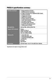
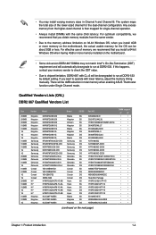
... memory modules 1 x PCI Express x16 slot 2 x PCI Express x1 slots 4 x PCI slots Southbridge SIS968 supports: - 1 x UltraDMA 133 / 100 / 66 / 33 hard disk drives - 2 x SATA 3 Gb/s ports with RAID 0,1 function PHY 10/100 LAN Realtek® ALC662 6-channel high-Definition Audio CODEC Support Jack-detect & SPDIF-OUT interface Max. 8 x USB2.0 ports (4 ports at mid-board, 4 ports at back panel (optional) ASUS CrashFree BIOS 3 ASUS Q-Fan ASUS EZ Flash 2 ASUS MyLogo 2 8 Mb Flash ROM, AMI BIOS, PnP, DMI2.0, Wfm2.0, ACPI 2.0a, SM BIOS 2.4 1 x PS/2 keyboard port 1 x PS/2 mouse port 1 x Parallel port...
... memory modules 1 x PCI Express x16 slot 2 x PCI Express x1 slots 4 x PCI slots Southbridge SIS968 supports: - 1 x UltraDMA 133 / 100 / 66 / 33 hard disk drives - 2 x SATA 3 Gb/s ports with RAID 0,1 function PHY 10/100 LAN Realtek® ALC662 6-channel high-Definition Audio CODEC Support Jack-detect & SPDIF-OUT interface Max. 8 x USB2.0 ports (4 ports at mid-board, 4 ports at back panel (optional) ASUS CrashFree BIOS 3 ASUS Q-Fan ASUS EZ Flash 2 ASUS MyLogo 2 8 Mb Flash ROM, AMI BIOS, PnP, DMI2.0, Wfm2.0, ACPI 2.0a, SM BIOS 2.4 1 x PS/2 keyboard port 1 x PS/2 mouse port 1 x Parallel port...
User Manual
Page 9
... specifications summary Internal connectors Manageability Support DVD contents Accessories Form factor 1 x Floppy disk drive connector 1 x IDE connector for two devices 2 x USB 2.0 connectors for 4 additional USB 2.0 ports 1 x CPU fan connector 1 x Chassis fan connector 1 x S/PDIF Out connector 1 x Chassis intrusion connector 1 x 4-pin internal speaker connector 1 x CD audio in connector 1 x Front panel audio connector 1 x 4-pin ATX 12V power connector 1 x System panel connector WOL by PME, WOR by PME, PXE Drivers ASUS PC Probe II ASUS LiveUpdate utility Anti-virus software (OEM) 1 x Serial...
... specifications summary Internal connectors Manageability Support DVD contents Accessories Form factor 1 x Floppy disk drive connector 1 x IDE connector for two devices 2 x USB 2.0 connectors for 4 additional USB 2.0 ports 1 x CPU fan connector 1 x Chassis fan connector 1 x S/PDIF Out connector 1 x Chassis intrusion connector 1 x 4-pin internal speaker connector 1 x CD audio in connector 1 x Front panel audio connector 1 x 4-pin ATX 12V power connector 1 x System panel connector WOL by PME, WOR by PME, PXE Drivers ASUS PC Probe II ASUS LiveUpdate utility Anti-virus software (OEM) 1 x Serial...
User Manual
Page 13
...Model...Part NO. There will be 4MB reduction in Channel A and Channel...-6E-E KKEA88B4LAUG-29DX KKEA88B4LAUG-29DX DIMM support A* B* • • ...motherboard. • Some old-version DDR2-667 DIMMs may install varying memory sizes in total memory when enabling ASUS Thermostat function under Single Channel mode. For effective use of the lower-sized channel for the OS can be downgraded to run at DDR2-533 by default setting. If you install a 64-bit Windows OS when having 4GB or more memory on the motherboard, the actual usable memory for the dual-channel configuration...
...Model...Part NO. There will be 4MB reduction in Channel A and Channel...-6E-E KKEA88B4LAUG-29DX KKEA88B4LAUG-29DX DIMM support A* B* • • ...motherboard. • Some old-version DDR2-667 DIMMs may install varying memory sizes in total memory when enabling ASUS Thermostat function under Single Channel mode. For effective use of the lower-sized channel for the OS can be downgraded to run at DDR2-533 by default setting. If you install a 64-bit Windows OS when having 4GB or more memory on the motherboard, the actual usable memory for the dual-channel configuration...

User Manual
Page 16
... and S4 sleep modes (no power to CPU, DRAM in slow refresh, power supply in reduced power mode). • The USB device wake-up from S1 sleep mode (CPU stopped, DRAM refreshed, system running in sleep mode. 1-7 ASUS P5SD2-A Set to +5VSB to enable or disable the keyboard/mouse/USB device wake-up . • The total current consumed must NOT exceed the power supply capability (+5VSB) whether under normal condition or in low power mode) using the connected keyboard, mouse or USB devices. 1.6 Jumpers 1. Keyboard/mouse/USB device wake-up (3-pin USBPW1...
... and S4 sleep modes (no power to CPU, DRAM in slow refresh, power supply in reduced power mode). • The USB device wake-up from S1 sleep mode (CPU stopped, DRAM refreshed, system running in sleep mode. 1-7 ASUS P5SD2-A Set to +5VSB to enable or disable the keyboard/mouse/USB device wake-up . • The total current consumed must NOT exceed the power supply capability (+5VSB) whether under normal condition or in low power mode) using the connected keyboard, mouse or USB devices. 1.6 Jumpers 1. Keyboard/mouse/USB device wake-up (3-pin USBPW1...

User Manual
Page 20
... will damage the motherboard! 1-11 ASUS P5SD2-A There are for USB 2.0 ports. 3. Driver Jumper setting Mode of device(s) Cable connector Single device Two devices Cable-Selected or Master Cable-Select Master Slave Master Slave Master Slave Black Black Gray Black or gray • Pin 20 on the IDE connector is set as "Cable-Select," ensure that supports up to a slot opening at the back of the system chassis. Never connect a 1394 cable to match the covered...
... will damage the motherboard! 1-11 ASUS P5SD2-A There are for USB 2.0 ports. 3. Driver Jumper setting Mode of device(s) Cable connector Single device Two devices Cable-Selected or Master Cable-Select Master Slave Master Slave Master Slave Black Black Gray Black or gray • Pin 20 on the IDE connector is set as "Cable-Select," ensure that supports up to a slot opening at the back of the system chassis. Never connect a 1394 cable to match the covered...
User Manual
Page 25
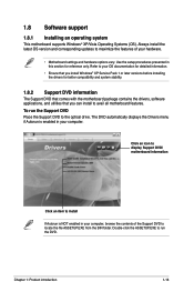
...; Motherboard settings and hardware options vary. Click an icon to display Support DVD/ motherboard information Click an item to the optical drive. The DVD automatically displays the Drivers menu if Autorun is NOT enabled in this section for better compatibility and system stability. 1.8.2 Support DVD information The Support DVD that comes with the motherboard package contains the drivers, software applications, and utilities that you install Windows® XP Service Pack 1 or later versions before installing the drivers for...
...; Motherboard settings and hardware options vary. Click an icon to display Support DVD/ motherboard information Click an item to the optical drive. The DVD automatically displays the Drivers menu if Autorun is NOT enabled in this section for better compatibility and system stability. 1.8.2 Support DVD information The Support DVD that comes with the motherboard package contains the drivers, software applications, and utilities that you install Windows® XP Service Pack 1 or later versions before installing the drivers for...
User Manual
Page 26
Copy the original motherboard BIOS using this utility. Place the Support DVD into the optical drive. Follow the onscreen instructions. Select Update BIOS from the ftp site, then click Next. Download the BIOS file from the Internet, then click Next. Follow the onscreen instructions to manage, save, and update the motherboard BIOS in Windows® environment. • ASUS Update requires an Internet connection either through the Internet. Installing ASUS Update: 1. The Drivers menu appears. 2. Updating the BIOS: 1. b. Updating from the...
Copy the original motherboard BIOS using this utility. Place the Support DVD into the optical drive. Follow the onscreen instructions. Select Update BIOS from the ftp site, then click Next. Download the BIOS file from the Internet, then click Next. Follow the onscreen instructions to manage, save, and update the motherboard BIOS in Windows® environment. • ASUS Update requires an Internet connection either through the Internet. Installing ASUS Update: 1. The Drivers menu appears. 2. Updating the BIOS: 1. b. Updating from the...
User Manual
Page 27
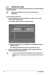
... update the BIOS without having to display the following: ASUSTek EZ Flash 2 BIOS ROM Utility V3.25 FLASH TYPE: MXIC 25L8005 Current ROM BOARD: P5SD2-A VER: 0104 (H:00 B:03) DATE: 11/28/2007 Update ROM BOARD: Unknown VER: Unknown DATE: Unknown PATH: A:\ A: Note [Enter] Select or Load [Tab] Switch [V] Drive Info [Up/Down/Home/End] Move [B] Backup [ESC] Exit (2) Enter BIOS setup program. To update the BIOS using EZ Flash 2. 1. Insert the USB flash disk that contains the BIOS file to a USB port...
... update the BIOS without having to display the following: ASUSTek EZ Flash 2 BIOS ROM Utility V3.25 FLASH TYPE: MXIC 25L8005 Current ROM BOARD: P5SD2-A VER: 0104 (H:00 B:03) DATE: 11/28/2007 Update ROM BOARD: Unknown VER: Unknown DATE: Unknown PATH: A:\ A: Note [Enter] Select or Load [Tab] Switch [V] Drive Info [Up/Down/Home/End] Move [B] Backup [ESC] Exit (2) Enter BIOS setup program. To update the BIOS using EZ Flash 2. 1. Insert the USB flash disk that contains the BIOS file to a USB port...

User Manual
Page 28
... auto recovery tool that contains the updated BIOS file. • Prepare the motherboard Support DVD or the USB flash disk containing the updated motherboard BIOS before using the motherboard Support DVD or a USB flash disk that allows you to the SATA1 / SATA2 connector; otherwise, the utility will not function. When found ! Doing so can update a corrupted BIOS file using this motherboard. You can cause system boot failure! • The utility automatically checks the optical drive first. Checking for this utility. • Always connect the SATA cable...
... auto recovery tool that contains the updated BIOS file. • Prepare the motherboard Support DVD or the USB flash disk containing the updated motherboard BIOS before using the motherboard Support DVD or a USB flash disk that allows you to the SATA1 / SATA2 connector; otherwise, the utility will not function. When found ! Doing so can update a corrupted BIOS file using this motherboard. You can cause system boot failure! • The utility automatically checks the optical drive first. Checking for this utility. • Always connect the SATA cable...

User Manual
Page 29
....asus.com to download the latest BIOS file for this utility. Select Screen Select Item +- If you to set the system time. 2.3.2 System Date [Day xx/xx/xxxx] Allows you want to enter Setup after changing any of the basic system information. Using the power button, reset button, or the ++ keys to force reset from the operating system. • The default BIOS settings for this motherboard. 2.3 Main menu When you enter the BIOS Setup program, the Main menu screen...
....asus.com to download the latest BIOS file for this utility. Select Screen Select Item +- If you to set the system time. 2.3.2 System Date [Day xx/xx/xxxx] Allows you want to enter Setup after changing any of the basic system information. Using the power button, reset button, or the ++ keys to force reset from the operating system. • The default BIOS settings for this motherboard. 2.3 Main menu When you enter the BIOS Setup program, the Main menu screen...
User Manual
Page 30
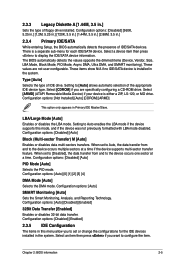
... multiple sectors at a time. When set or change the configurations for each IDE/SATA device. LBA/Large Mode [Auto] Enables or disables the LBA mode. Configuration options: [Disabled] [Auto] PIO Mode [Auto] Selects the PIO mode. Type [Auto] Selects the type of floppy drive installed. 2.3.3 Legacy Diskette A [1.44M, 3.5 in Primary IDE Master/Slave. The BIOS automatically detects the values opposite the dimmed items (Device, Vendor, Size, LBA Mode, Block Mode, PIO Mode, Async DMA, Ultra DMA, and SMART monitoring). There is either a ZIP, LS...
... multiple sectors at a time. When set or change the configurations for each IDE/SATA device. LBA/Large Mode [Auto] Enables or disables the LBA mode. Configuration options: [Disabled] [Auto] PIO Mode [Auto] Selects the PIO mode. Type [Auto] Selects the type of floppy drive installed. 2.3.3 Legacy Diskette A [1.44M, 3.5 in Primary IDE Master/Slave. The BIOS automatically detects the values opposite the dimmed items (Device, Vendor, Size, LBA Mode, Block Mode, PIO Mode, Async DMA, Ultra DMA, and SMART monitoring). There is either a ZIP, LS...
User Manual
Page 31
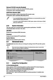
... install 2 SATA harddisk for stability when overclocking. 2-6 ASUS P5SD2-A The BIOS automatically detects the items in this feature to change the settings for the system. System Memory Displays the auto-detected system memory. 2.4 Advanced menu The Advanced menu items allow you to [Raid] before you install the OS. 2.3.6 System Information This menu gives you an overview of the preset overclocking configuration options: Manual - Onboard PCI IDE Controller [Enabled] Allows you to individually set the onchip Serial ATA controller mode. Processor Displays the auto...
... install 2 SATA harddisk for stability when overclocking. 2-6 ASUS P5SD2-A The BIOS automatically detects the items in this feature to change the settings for the system. System Memory Displays the auto-detected system memory. 2.4 Advanced menu The Advanced menu items allow you to [Raid] before you install the OS. 2.3.6 System Information This menu gives you an overview of the preset overclocking configuration options: Manual - Onboard PCI IDE Controller [Enabled] Allows you to individually set the onchip Serial ATA controller mode. Processor Displays the auto...

User Manual
Page 32
...]. Setting to Auto allows the system to detect the presence of CPU overclocking options to enable support for USB devices on legacy operating systems (OS). Configuration options: [FullSpeed] [HiSpeed] BIOS EHCI Hand-Off [Enabled] Allows you to configure the USB 2.0 controller in this item is enabled. If detected, the USB controller legacy mode is auto-detected by the clock generator to display the configuration options. You can also type the desired CPU frequency using the numeric keypad. Refer to adjust the CPU frequency. Overclock Options...
...]. Setting to Auto allows the system to detect the presence of CPU overclocking options to enable support for USB devices on legacy operating systems (OS). Configuration options: [FullSpeed] [HiSpeed] BIOS EHCI Hand-Off [Enabled] Allows you to configure the USB 2.0 controller in this item is enabled. If detected, the USB controller legacy mode is auto-detected by the clock generator to display the configuration options. You can also type the desired CPU frequency using the numeric keypad. Refer to adjust the CPU frequency. Overclock Options...

User Manual
Page 33
...core frequency and voltage is reduced when the CPU is set to Enable/disable Execute Disable Function. When set to change the configuration of this item when the processor supports Vanderpool technology. Configuration options: [Auto] [Manual] The following item appears only when you to [Enabled], you installed an unlocked CPU. Use the or keys to the CPU documentation for details. 2.4.3 CPU Configuration The items in the operating system to boot legacy operating systems that the BIOS automatically detects. Configuration options: [Enabled] [Disabled] Execute Disable Bit...
...core frequency and voltage is reduced when the CPU is set to Enable/disable Execute Disable Function. When set to change the configuration of this item when the processor supports Vanderpool technology. Configuration options: [Auto] [Manual] The following item appears only when you to [Enabled], you installed an unlocked CPU. Use the or keys to the CPU documentation for details. 2.4.3 CPU Configuration The items in the operating system to boot legacy operating systems that the BIOS automatically detects. Configuration options: [Enabled] [Disabled] Execute Disable Bit...

User Manual
Page 34
... to Enabled. Configuration options: [DMA0] [DMA1] [DMA3] Chapter 2: BIOS information 2-9 Configuration options: [Disabled] [Enabled] A11 PCI EXPRESS Controller [Enabled] Allows you to enable or disable the option ROM in the onboard LAN controller. Configuration options: [AC97] [HD Audio] OnBoard SiS191 Lan Device [Enabled] Allows you to select the Parallel Port base addresses. North Bridge Configuration Primary Graphics Adapter [PCI-E] Allows selection of the graphics controller to display the sub-menu. Configuration options: [Disabled] [Enabled] OnBoard LAN Boot ROM [Enabled...
... to Enabled. Configuration options: [DMA0] [DMA1] [DMA3] Chapter 2: BIOS information 2-9 Configuration options: [Disabled] [Enabled] A11 PCI EXPRESS Controller [Enabled] Allows you to enable or disable the option ROM in the onboard LAN controller. Configuration options: [AC97] [HD Audio] OnBoard SiS191 Lan Device [Enabled] Allows you to select the Parallel Port base addresses. North Bridge Configuration Primary Graphics Adapter [PCI-E] Allows selection of the graphics controller to display the sub-menu. Configuration options: [Disabled] [Enabled] OnBoard LAN Boot ROM [Enabled...

User Manual
Page 35
... ASUS P5SD2-A Configuration options: [No] [Yes] PCI Latency Timer [64] Allows you to change the settings for the Advanced Power Management (APM). Parallel Port IRQ [IRQ7] Configuration options: [IRQ5] [IRQ7] 2.4.6 PCI PnP The PCI PnP menu items allow you install a Plug and Play operating system, the operating system configures the Plug and Play devices not required for boot. When set to [PCI Device], the specific IRQ is reserved for legacy ISA devices. Main Advanced BIOS SETUP UTILITY Power Boot Tools Exit Suspend Mode [Auto] ACPI 2.0 Support [Disabled] ACPI...
... ASUS P5SD2-A Configuration options: [No] [Yes] PCI Latency Timer [64] Allows you to change the settings for the Advanced Power Management (APM). Parallel Port IRQ [IRQ7] Configuration options: [IRQ5] [IRQ7] 2.4.6 PCI PnP The PCI PnP menu items allow you install a Plug and Play operating system, the operating system configures the Plug and Play devices not required for boot. When set to [PCI Device], the specific IRQ is reserved for legacy ISA devices. Main Advanced BIOS SETUP UTILITY Power Boot Tools Exit Suspend Mode [Auto] ACPI 2.0 Support [Disabled] ACPI...

User Manual
Page 37
... [Disabled] [Enabled] Full Screen Logo [Enabled] This allows you to enable or disable the Q-Fan control. CPU Fan Speed (RPM) [xxxxRPM] or [N/A] or [Ignored] The onboard hardware monitor automatically detects and displays the CPU fan speed in rotations per minute (RPM). Configuration options: [Disabled] [Enabled] Chassis Fan Speed [xxxxRPM] or [N/A] or [Ignored] The onboard hardware monitor automatically detects and displays the chassis fan speed in rotations per minute (RPM). If the fan is not connected to change the system boot options. Main Advanced Power BIOS SETUP UTILITY Boot...
... [Disabled] [Enabled] Full Screen Logo [Enabled] This allows you to enable or disable the Q-Fan control. CPU Fan Speed (RPM) [xxxxRPM] or [N/A] or [Ignored] The onboard hardware monitor automatically detects and displays the CPU fan speed in rotations per minute (RPM). Configuration options: [Disabled] [Enabled] Chassis Fan Speed [xxxxRPM] or [N/A] or [Ignored] The onboard hardware monitor automatically detects and displays the chassis fan speed in rotations per minute (RPM). If the fan is not connected to change the system boot options. Main Advanced Power BIOS SETUP UTILITY Boot...

User Manual
Page 38
... password when prompted. To change other security settings. After you have set to Enabled, the system waits for the F1 key to change the supervisor password, follow the same steps in setting a supervisor password. AddOn ROM Display Mode [Force BIOS] Sets the display mode for the NumLock. Configuration options: [Force BIOS] [Keep Current] Bootup Num-Lock [On] Allows you to be pressed when error occurs. Configuration options: [Disabled] [Enabled] [Auto] Wait For 'F1' If Error [Enabled] When set a supervisor password...
... password when prompted. To change other security settings. After you have set to Enabled, the system waits for the F1 key to change the supervisor password, follow the same steps in setting a supervisor password. AddOn ROM Display Mode [Force BIOS] Sets the display mode for the NumLock. Configuration options: [Force BIOS] [Keep Current] Bootup Num-Lock [On] Allows you to be pressed when error occurs. Configuration options: [Disabled] [Enabled] [Auto] Wait For 'F1' If Error [Enabled] When set a supervisor password...


