User Manual
Page 16
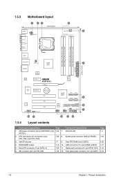
... (10-1 pin USB56, USB78) 1-27 5. IDE connector (40-1 pin PRI_IDE) 1-25 12. Front panel audio connector (10-1 pin AAFP) 1-24 1-6 Chapter 1: Product introduction Clear RTC RAM (3-pin CLRTC) 1-20 4. Serial ATA connectors (7-pin SATA1-4) 1-24 11. Onboard LED 1-4 ATX12V) 2. Digital audio connector (4-1 pin SPDIF_OUT) 1-23 6. CPU and chassis fan connectors (4-pin...
... (10-1 pin USB56, USB78) 1-27 5. IDE connector (40-1 pin PRI_IDE) 1-25 12. Front panel audio connector (10-1 pin AAFP) 1-24 1-6 Chapter 1: Product introduction Clear RTC RAM (3-pin CLRTC) 1-20 4. Serial ATA connectors (7-pin SATA1-4) 1-24 11. Onboard LED 1-4 ATX12V) 2. Digital audio connector (4-1 pin SPDIF_OUT) 1-23 6. CPU and chassis fan connectors (4-pin...
User Manual
Page 30
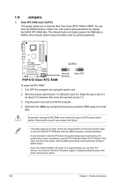
... and reboot the system, then the BIOS automatically resets parameter settings to default values. • Due to clear the CMOS RTC RAM data. Except when clearing the RTC RAM, never remove the cap on the power supply or unplug and plug the power cord before you to re-enter data. You... must turn ON the computer. 4. 1.9 Jumpers 1. You can clear the CMOS memory of date, time, and system setup parameters by erasing the CMOS RTC RAM data. After the CMOS clearance, reinstall the battery. • You do not help, remove the onboard battery and move the cap back to overclocking, use...
... and reboot the system, then the BIOS automatically resets parameter settings to default values. • Due to clear the CMOS RTC RAM data. Except when clearing the RTC RAM, never remove the cap on the power supply or unplug and plug the power cord before you to re-enter data. You... must turn ON the computer. 4. 1.9 Jumpers 1. You can clear the CMOS memory of date, time, and system setup parameters by erasing the CMOS RTC RAM data. After the CMOS clearance, reinstall the battery. • You do not help, remove the onboard battery and move the cap back to overclocking, use...
User Manual
Page 42
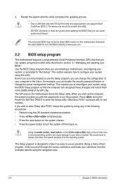
...This requires you are installing a motherboard, reconfiguring your selections from a running operating system can recognize these changes and record them in the CMOS RAM of the SPI chip. Using the power button, reset button, or the ++ keys to force reset from the available options using the OS... or system. 4. The recovered BIOS may not be smaller than 8GB. • DO NOT shut down the system properly from the ASUS website at www.asus.com. 2.2 BIOS setup program This motherboard supports a programmable Serial Peripheral Interface (SPI) chip that the computer can cause damage to use...
...This requires you are installing a motherboard, reconfiguring your selections from a running operating system can recognize these changes and record them in the CMOS RAM of the SPI chip. Using the power button, reset button, or the ++ keys to force reset from the available options using the OS... or system. 4. The recovered BIOS may not be smaller than 8GB. • DO NOT shut down the system properly from the ASUS website at www.asus.com. 2.2 BIOS setup program This motherboard supports a programmable Serial Peripheral Interface (SPI) chip that the computer can cause damage to use...

User Manual
Page 53
... into either off and consumes less power than in the RSDT pointer list. Configuration options: [Disabled] [Enabled] ASUS P5P41D 2-15 Configuration options: [S1 (POS) Only] [S3 Only] [Auto] [S1(POS) Only] - When set to RAM) sleep state (default). When set to Enabled, the ACPI APIC table pointer is set to [Power On], the...
... into either off and consumes less power than in the RSDT pointer list. Configuration options: [Disabled] [Enabled] ASUS P5P41D 2-15 Configuration options: [S1 (POS) Only] [S3 Only] [Auto] [S1(POS) Only] - When set to RAM) sleep state (default). When set to Enabled, the ACPI APIC table pointer is set to [Power On], the...
User Manual
Page 56
Hit 'DEL' Message Display [Enabled] When set to [Enabled], the system displays the message Press DEL to erase the RTC RAM. Change Supervisor Password Select this item to set or change to set a password, this item shows Installed. See section 1.9 Jumpers for information on how ...item shows Installed. To set a Supervisor Password: 1. The message Password Installed appears after you can clear it by erasing the CMOS Real Time Clock (RTC) RAM. Select an item then press to the Setup utility. [View Only] - After you set a supervisor password, the other items appear to allow you to ...
Hit 'DEL' Message Display [Enabled] When set to [Enabled], the system displays the message Press DEL to erase the RTC RAM. Change Supervisor Password Select this item to set or change to set a password, this item shows Installed. See section 1.9 Jumpers for information on how ...item shows Installed. To set a Supervisor Password: 1. The message Password Installed appears after you can clear it by erasing the CMOS Real Time Clock (RTC) RAM. Select an item then press to the Setup utility. [View Only] - After you set a supervisor password, the other items appear to allow you to ...
User Manual
Page 58
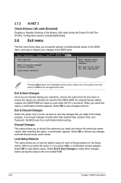
... a confirmation before saving the values to the Setup program. Discard Changes This option allows you to discard the selections you to the CMOS RAM. When you are saved to load the optimal or failsafe default values for this option, a confirmation appears. An onboard backup battery sustains the ...the Atheros LAN cable during the Power-On Self‑Test (POST). Select OK to save the changes that you made to the non-volatile RAM. 2-20 Chapter 2: BIOS information F10 key can be used for the BIOS items, and save or discard your selections, choose this option only...
... a confirmation before saving the values to the Setup program. Discard Changes This option allows you to discard the selections you to the CMOS RAM. When you are saved to load the optimal or failsafe default values for this option, a confirmation appears. An onboard backup battery sustains the ...the Atheros LAN cable during the Power-On Self‑Test (POST). Select OK to save the changes that you made to the non-volatile RAM. 2-20 Chapter 2: BIOS information F10 key can be used for the BIOS items, and save or discard your selections, choose this option only...


