
User Guide
Page 6
... 6-13 6.3.1 Windows® 2000 Server 6-13 6.3.2 Windows® 2003 Server 6-14 6.3.3 Red Hat® Enterprise ver. 3.0 6-14 6.4 Management applications and utilities installation 6-15 6.4.1 Running the support CD 6-15 6.4.2 Drivers menu 6-15 6.4.3 Management Software menu 6-16 6.4.4 Utilities menu 6-16 6.4.5 Contact information 6-16 Appendix: Reference information A.1 Intel® EM64T A-1 A.2 Enhanced Intel SpeedStep®...
... 6-13 6.3.1 Windows® 2000 Server 6-13 6.3.2 Windows® 2003 Server 6-14 6.3.3 Red Hat® Enterprise ver. 3.0 6-14 6.4 Management applications and utilities installation 6-15 6.4.1 Running the support CD 6-15 6.4.2 Drivers menu 6-15 6.4.3 Management Software menu 6-16 6.4.4 Utilities menu 6-16 6.4.5 Contact information 6-16 Appendix: Reference information A.1 Intel® EM64T A-1 A.2 Enhanced Intel SpeedStep®...

User Guide
Page 9
...Refer to perform when installing system components. ASUS websites The ASUS website provides updated information on the motherboard. • Chapter 3: Powering up This chapter describes the power up sequence, the vocal POST messages, and ways of the motherboard and the new technology it supports. • Chapter 2: Hardware information ... the standard package. Detailed descriptions of the BIOS parameters are not part of the switches, jumpers, and connectors on ASUS hardware and software products. ix About this guide This user guide contains the information you may have to the...
...Refer to perform when installing system components. ASUS websites The ASUS website provides updated information on the motherboard. • Chapter 3: Powering up This chapter describes the power up sequence, the vocal POST messages, and ways of the motherboard and the new technology it supports. • Chapter 2: Hardware information ... the standard package. Detailed descriptions of the BIOS parameters are not part of the switches, jumpers, and connectors on ASUS hardware and software products. ix About this guide This user guide contains the information you may have to the...
User Guide
Page 11
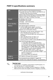
P5MT-S specifications summary CPU Chipset Front Side Bus Memory Expansion slots * Storage Graphics Dual LAN LGA775 socket for Intel® Pentium®4/processor Compatible with Intel® PCG 05B/05A and 04B/04A and the latest Intel® dual-core processor Supports Intel® Enhanced Memory 64 Technology (EM64T) Supports...-bit slot (PCI-X 1.0) 1 x PCI 33 MHz/32-bit/5V slot (PCI 2.3) 1 x mini-PCI socket for ASUS® Server Management Board Intel® ICH7R Southbridge supports: - 2 x Ultra DMA 100/66/33 hard disk drives - 4 x SATA-300 drives with RAID functionality using the ...
P5MT-S specifications summary CPU Chipset Front Side Bus Memory Expansion slots * Storage Graphics Dual LAN LGA775 socket for Intel® Pentium®4/processor Compatible with Intel® PCG 05B/05A and 04B/04A and the latest Intel® dual-core processor Supports Intel® Enhanced Memory 64 Technology (EM64T) Supports...-bit slot (PCI-X 1.0) 1 x PCI 33 MHz/32-bit/5V slot (PCI 2.3) 1 x mini-PCI socket for ASUS® Server Management Board Intel® ICH7R Southbridge supports: - 2 x Ultra DMA 100/66/33 hard disk drives - 4 x SATA-300 drives with RAID functionality using the ...

User Guide
Page 12
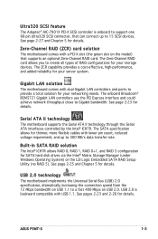
P5MT-S specifications summary USB Special features BIOS features Rear panel Internal connectors Power Requirement Form Factor Support CD contents Intel ICH7R Southbridge supports: - 4 USB 2.0 ports (two on the rear panel, two on the front panel) ASUS Smart Fan I/II ASUS CrashFree BIOS 2 ASUS MyLogo2 AMI... x SMBus header for back-plane 1 x 20-1 pin auxiliary panel connector 1 x 20-1 pin system panel connector 1 x Serial port (COM2) connector 1 x ASUS server management (BMC) connector SSI power supply (with 24-pin and 8-pin 12 V plugs) ATX 12 V 2.0 compliant ATX form factor: 12 in x 9.8 in...
P5MT-S specifications summary USB Special features BIOS features Rear panel Internal connectors Power Requirement Form Factor Support CD contents Intel ICH7R Southbridge supports: - 4 USB 2.0 ports (two on the rear panel, two on the front panel) ASUS Smart Fan I/II ASUS CrashFree BIOS 2 ASUS MyLogo2 AMI... x SMBus header for back-plane 1 x 20-1 pin auxiliary panel connector 1 x 20-1 pin system panel connector 1 x Serial port (COM2) connector 1 x ASUS server management (BMC) connector SSI power supply (with 24-pin and 8-pin 12 V plugs) ATX 12 V 2.0 compliant ATX form factor: 12 in x 9.8 in...

User Guide
Page 13
This chapter describes the motherboard features and the new technologies it supports. 1Product introduction
This chapter describes the motherboard features and the new technologies it supports. 1Product introduction

User Guide
Page 15
... drive cable I/O shield ASUS motherboard support CD User guide If any of ASUS quality motherboards! The motherboard delivers a host of new features and latest technologies, making it , check the items in your package with the list below. 1.2 Package contents Check your retailer. Before you for the following items. Motherboard ASUS P5MT-S motherboard Cables Accessories Application...
... drive cable I/O shield ASUS motherboard support CD User guide If any of ASUS quality motherboards! The motherboard delivers a host of new features and latest technologies, making it , check the items in your package with the list below. 1.2 Package contents Check your retailer. Before you for the following items. Motherboard ASUS P5MT-S motherboard Cables Accessories Application...

User Guide
Page 16
...details. The MCH provides the processor, dual-channel DDR2-533/667 memory, and PCI Express interfaces. DDR2-667 memory support The motherboard supports DDR2 memory which features data transfer rates of up to 667 MHz to boost system performance, eliminating bottlenecks with existing PCI...PCI bus. The ICH is software compatible with peak bandwidths of the latest server applications. PCI Express™ interface The motherboard fully supports PCI Express, the latest I/O interconnect technology that provides the interface for the motherboard. This high speed interface is a new generation...
...details. The MCH provides the processor, dual-channel DDR2-533/667 memory, and PCI Express interfaces. DDR2-667 memory support The motherboard supports DDR2 memory which features data transfer rates of up to 667 MHz to boost system performance, eliminating bottlenecks with existing PCI...PCI bus. The ICH is software compatible with peak bandwidths of the latest server applications. PCI Express™ interface The motherboard fully supports PCI Express, the latest I/O interconnect technology that provides the interface for the motherboard. This high speed interface is a new generation...
User Guide
Page 17
...23 for details. See page 2-25 and Chapter 5 for details. USB 2.0 is onboard to support one 68-pin Ultra320 SCSI connector, that supports an optional Zero-Channel RAID card. Ultra320 SCSI feature The Adaptec® AIC-7901X PCI-X ...SCSI controller is backward compatible with dual Gigabit LAN controllers and ports to provide a total solution for your server system. The ZCR capability provides a cost-effective, high-performance, and added reliability for details. ASUS P5MT...
...23 for details. See page 2-25 and Chapter 5 for details. USB 2.0 is onboard to support one 68-pin Ultra320 SCSI connector, that supports an optional Zero-Channel RAID card. Ultra320 SCSI feature The Adaptec® AIC-7901X PCI-X ...SCSI controller is backward compatible with dual Gigabit LAN controllers and ports to provide a total solution for your server system. The ZCR capability provides a cost-effective, high-performance, and added reliability for details. ASUS P5MT...
User Guide
Page 18
..., fan, and voltage monitoring The CPU temperature is monitored for timely failure detection. ASUS Smart Fan technology I/II The motherboard supports both generations of current for critical components. ASUS MyLogo2™ This new feature present in the motherboard allows you to ensure stable supply... of ASUS Smart Fan technology. See page 4-35 for details. The system fan rotations per...
..., fan, and voltage monitoring The CPU temperature is monitored for timely failure detection. ASUS Smart Fan technology I/II The motherboard supports both generations of current for critical components. ASUS MyLogo2™ This new feature present in the motherboard allows you to ensure stable supply... of ASUS Smart Fan technology. See page 4-35 for details. The system fan rotations per...

User Guide
Page 28
Refer to prevent bending the connectors on these CPU features. 2-8 Chapter 2: Hardware information B The motherboard supports Intel® Pentium® 4 LGA775 processors with the Intel® Enhanced Memory 64 Technology (EM64T), Enhanced Intel SpeedStep® Technology (EIST), and Hyper-Threading Technology. Close the load plate (A), then A push the load lever (B) until it snaps into the socket to the Appendix for more information on the socket and damaging the CPU! 6. The CPU fits in only one correct orientation. DO NOT force the CPU into the retention tab.
Refer to prevent bending the connectors on these CPU features. 2-8 Chapter 2: Hardware information B The motherboard supports Intel® Pentium® 4 LGA775 processors with the Intel® Enhanced Memory 64 Technology (EM64T), Enhanced Intel SpeedStep® Technology (EIST), and Hyper-Threading Technology. Close the load plate (A), then A push the load lever (B) until it snaps into the socket to the Appendix for more information on the socket and damaging the CPU! 6. The CPU fits in only one correct orientation. DO NOT force the CPU into the retention tab.

User Guide
Page 34
... the notch on the DIMM matches the break on 1 the socket. 3. The DIMM might get damaged when it fits in only one direction. Support the DIMM lightly with extra force. Unlock a DIMM socket by pressing the retaining clips outward. 2. Align a DIMM on the socket such that it &#... outward to remove a DIMM. 1. 2.4.3 Installing a DIMM Unplug the power supply before adding or removing DIMMs or other system components. Failure to do not support DDR DIMMs. DO NOT install DDR DIMMs to the DDR2 DIMM sockets. 2.4.4 Removing a DIMM Follow these steps to unlock the DIMM.
... the notch on the DIMM matches the break on 1 the socket. 3. The DIMM might get damaged when it fits in only one direction. Support the DIMM lightly with extra force. Unlock a DIMM socket by pressing the retaining clips outward. 2. Align a DIMM on the socket such that it &#... outward to remove a DIMM. 1. 2.4.3 Installing a DIMM Unplug the power supply before adding or removing DIMMs or other system components. Failure to do not support DDR DIMMs. DO NOT install DDR DIMMs to the DDR2 DIMM sockets. 2.4.4 Removing a DIMM Follow these steps to unlock the DIMM.
User Guide
Page 35
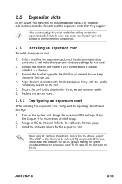
...between the two PCI groups, making the system unstable and the card inoperable. Refer to the table on shared slots, ensure that the drivers support "Share IRQ" or that came with the slot and press firmly until the card is already installed in a chassis). 3. Failure...install expansion cards. Remove the bracket opposite the slot that they support. Replace the system cover. 2.5.2 Configuring an expansion card After installing the expansion card, configure it and make the necessary hardware settings for the card. 2. ASUS P5MT-S 2-15 2.5 Expansion slots In the future, you may ...
...between the two PCI groups, making the system unstable and the card inoperable. Refer to the table on shared slots, ensure that the drivers support "Share IRQ" or that came with the slot and press firmly until the card is already installed in a chassis). 3. Failure...install expansion cards. Remove the bracket opposite the slot that they support. Replace the system cover. 2.5.2 Configuring an expansion card After installing the expansion card, configure it and make the necessary hardware settings for the card. 2. ASUS P5MT-S 2-15 2.5 Expansion slots In the future, you may ...

User Guide
Page 37
... socket ASUS P5MT-S 2-17 PCI Express I/O cards may run at x1 speed due to chipset limitation. A PCI Express graphics card may only run only at x8 or x4 speed. 2.5.6 Mini-PCI socket The mini-PCI socket on the motherboard supports an ASUS Server Management Board. 2.5.4 PCI/PCI-X slots The PCI and PCI-X slots support cards... shows a graphics card installed on PCI_X2 slot that is colored green. 32-bit PCI slot 64-bit PCI-X slot 2.5.5 PCI Express x16 slot This motherboard supports PCI Express x16 graphics cards that comply with the PCI Express specifications.
... socket ASUS P5MT-S 2-17 PCI Express I/O cards may run at x1 speed due to chipset limitation. A PCI Express graphics card may only run only at x8 or x4 speed. 2.5.6 Mini-PCI socket The mini-PCI socket on the motherboard supports an ASUS Server Management Board. 2.5.4 PCI/PCI-X slots The PCI and PCI-X slots support cards... shows a graphics card installed on PCI_X2 slot that is colored green. 32-bit PCI slot 64-bit PCI-X slot 2.5.5 PCI Express x16 slot This motherboard supports PCI Express x16 graphics cards that comply with the PCI Express specifications.

User Guide
Page 42
...: 1. Set the jumper to pins 1-2. 6. Force BIOS recovery setting (3-pin RECOVERY1) This jumper allows you to activate the SCSI feature, and support RAID configurations. ® P5MT-S SCSI_EN1 1 2 Enable (Default) P5MT-S SCSI Controller Setting 2 3 Disable 9. Set to pins 1-2 to enable or disable the onboard Adaptec AIC-7901X PCI-X U320 SCSI controller. 8. Insert...
...: 1. Set the jumper to pins 1-2. 6. Force BIOS recovery setting (3-pin RECOVERY1) This jumper allows you to activate the SCSI feature, and support RAID configurations. ® P5MT-S SCSI_EN1 1 2 Enable (Default) P5MT-S SCSI Controller Setting 2 3 Disable 9. Set to pins 1-2 to enable or disable the onboard Adaptec AIC-7901X PCI-X U320 SCSI controller. 8. Insert...

User Guide
Page 46
.../SATA Card Activity LED Connector 5. USB connector (10-1 pin USB34) This connector is purchased separately. ® P5MT-S USB+5V USB_P3USB_P3+ GND NC USB+5V USB_P2USB_P2+ GND 2-26 Chapter 2: Hardware information Connect the USB module cable to this LED to... LED. The read or write activities of the system chassis. This USB connector complies with USB 2.0 specification that supports up . ® P5MT-S NC ADD_IN_CARD_ACT# ADD_IN_CARD_ACT# NC 4. USB34 P5MT-S USB 2.0 Connector The USB port module is for USB 2.0 ports. Hard disk activity LED connector (4-pin HDLED1) This ...
.../SATA Card Activity LED Connector 5. USB connector (10-1 pin USB34) This connector is purchased separately. ® P5MT-S USB+5V USB_P3USB_P3+ GND NC USB+5V USB_P2USB_P2+ GND 2-26 Chapter 2: Hardware information Connect the USB module cable to this LED to... LED. The read or write activities of the system chassis. This USB connector complies with USB 2.0 specification that supports up . ® P5MT-S NC ADD_IN_CARD_ACT# ADD_IN_CARD_ACT# NC 4. USB34 P5MT-S USB 2.0 Connector The USB port module is for USB 2.0 ports. Hard disk activity LED connector (4-pin HDLED1) This ...

User Guide
Page 47
... onboard SCSI chipset incorporates an advanced multimode I/O cell that supports one type of 15 SCSI devices as specified. ASUS P5MT-S 2-27 SCSIA1 68-Pin Ultra320/ 1 35 Ultra2-Wide SCSI Connector ® P5MT-S 34 68 P5MT-S Onboard SCSI Connector SCSI Connection Notes This motherboard has a...Connect SCSI devices as specified by Ultra320 standards. Ultra320, Ultra160, Ultra2, Ultra-Wide). The SCSI channel can support a maximum of SCSI standard (e.g. 6. Ultra320 SCSI connector (68-pin SCSIA1) This motherboard comes with the Adaptec AIC-7901X PCI-X ...
... onboard SCSI chipset incorporates an advanced multimode I/O cell that supports one type of 15 SCSI devices as specified. ASUS P5MT-S 2-27 SCSIA1 68-Pin Ultra320/ 1 35 Ultra2-Wide SCSI Connector ® P5MT-S 34 68 P5MT-S Onboard SCSI Connector SCSI Connection Notes This motherboard has a...Connect SCSI devices as specified by Ultra320 standards. Ultra320, Ultra160, Ultra2, Ultra-Wide). The SCSI channel can support a maximum of SCSI standard (e.g. 6. Ultra320 SCSI connector (68-pin SCSIA1) This motherboard comes with the Adaptec AIC-7901X PCI-X ...

User Guide
Page 49
...max.) at +12V. Devices communicate with an SMBus host and/or other SMBus devices using the SMBus interface. ® P5MT-S FANOUT I2C_CLK GND I2C_DATA +5V 1 BPSMB1 P5MT-S SMBus Connector ASUS P5MT-S 2-29 10. These are not jumpers! Do not forget to connect the fan cables to connect SMBus (System Management Bus... flow inside the system may damage the motherboard components. CPU and system fan connectors (3-pin CPU_FAN1/2, REAR_FAN1/2, FRNT_FAN1/2) The fan connectors support cooling fans of 350 mA ~ 740 mA (8.88 W max.) or a total of the connector. Connect the fan cables to the fan...
...max.) at +12V. Devices communicate with an SMBus host and/or other SMBus devices using the SMBus interface. ® P5MT-S FANOUT I2C_CLK GND I2C_DATA +5V 1 BPSMB1 P5MT-S SMBus Connector ASUS P5MT-S 2-29 10. These are not jumpers! Do not forget to connect the fan cables to connect SMBus (System Management Bus... flow inside the system may damage the motherboard components. CPU and system fan connectors (3-pin CPU_FAN1/2, REAR_FAN1/2, FRNT_FAN1/2) The fan connectors support cooling fans of 350 mA ~ 740 mA (8.88 W max.) or a total of the connector. Connect the fan cables to the fan...

User Guide
Page 50
... default, four ATX12V2 connector pins are for the power supply SMB cable, if your power supply supports the SMBus function. ® P5MT-S PSU_I2CCLK PSU_I2CDATA NC GND +3.3V Remote Sense PSUSMB1 P5MT-S Power Supply SMBus Connector 13. SSI power connectors (24-pin ATXPWR1, 8-pin ATX12V2) These connectors...+3 Volts +3 Volts Ground +5 Volts Ground +5 Volts Ground Power OK +5V Standby +12 Volts +12 Volts +3 Volts ® P5MT-S +12V DC +12V DC +12V DC +12V DC 1 P5MT-S ATX Power Connectors 2-30 +3 Volts -12 Volts Ground PSON# Ground Ground Ground -5 Volts +5 Volts +5 Volts +5 Volts Ground ...
... default, four ATX12V2 connector pins are for the power supply SMB cable, if your power supply supports the SMBus function. ® P5MT-S PSU_I2CCLK PSU_I2CDATA NC GND +3.3V Remote Sense PSUSMB1 P5MT-S Power Supply SMBus Connector 13. SSI power connectors (24-pin ATXPWR1, 8-pin ATX12V2) These connectors...+3 Volts +3 Volts Ground +5 Volts Ground +5 Volts Ground Power OK +5V Standby +12 Volts +12 Volts +3 Volts ® P5MT-S +12V DC +12V DC +12V DC +12V DC 1 P5MT-S ATX Power Connectors 2-30 +3 Volts -12 Volts Ground PSON# Ground Ground Ground -5 Volts +5 Volts +5 Volts +5 Volts Ground ...

User Guide
Page 52
...to hear system beeps and warnings. • ATX power button/soft-off the system power. ® P5MT-S POWERLED+ GND POWERLEDMLED+ MLEDNC +5V GND GND SPKROUT 2-32 PANEL1 P5MT-S System Panel Connector The system panel connector is for easy connection. The IDE LED lights up when you...speaker allows you turn on the BIOS settings. The message LED indicates the booting status. System panel connector (20-pin PANEL1) This connector supports several chassis-mounted functions. • System power LED (Green 3-pin PLED) This 3-pin connector is for the message LED cable that ...
...to hear system beeps and warnings. • ATX power button/soft-off the system power. ® P5MT-S POWERLED+ GND POWERLEDMLED+ MLEDNC +5V GND GND SPKROUT 2-32 PANEL1 P5MT-S System Panel Connector The system panel connector is for easy connection. The IDE LED lights up when you...speaker allows you turn on the BIOS settings. The message LED indicates the booting status. System panel connector (20-pin PANEL1) This connector supports several chassis-mounted functions. • System power LED (Green 3-pin PLED) This 3-pin connector is for the message LED cable that ...
User Guide
Page 59
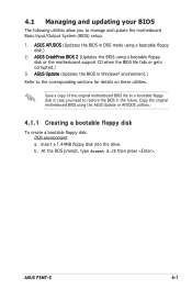
ASUS P5MT-S 4-1 Copy the original motherboard BIOS using a bootable floppy disk or the motherboard support CD when the BIOS file fails or gets corrupted.) 3. Save a copy of the original motherboard BIOS file to a bootable floppy disk in ...case you to manage and update the motherboard Basic Input/Output System (BIOS) setup. 1. ASUS Update (Updates the BIOS in...
ASUS P5MT-S 4-1 Copy the original motherboard BIOS using a bootable floppy disk or the motherboard support CD when the BIOS file fails or gets corrupted.) 3. Save a copy of the original motherboard BIOS file to a bootable floppy disk in ...case you to manage and update the motherboard Basic Input/Output System (BIOS) setup. 1. ASUS Update (Updates the BIOS in...