
User Manual
Page 4
... off the computer 3-2 3.2.1 Using the OS shut down function 3-2 3.2.2 Using the dual function power switch 3-2 Chapter 4: BIOS setup 4.1 Managing and updating your BIOS 4-1 4.1.1 Creating a bootable floppy disk 4-1 4.1.2 AFUDOS utility 4-2 4.1.3 ASUS CrashFree BIOS 2 utility 4-5 4.1.4 ASUS Update utility 4-7 4.2 BIOS setup program 4-10 4.2.1 BIOS menu screen 4-11 4.2.2 Menu bar 4-11 4.2.3 Navigation keys 4-11 4.2.4 Menu items 4-12 4.2.5 Sub-menu items...
... off the computer 3-2 3.2.1 Using the OS shut down function 3-2 3.2.2 Using the dual function power switch 3-2 Chapter 4: BIOS setup 4.1 Managing and updating your BIOS 4-1 4.1.1 Creating a bootable floppy disk 4-1 4.1.2 AFUDOS utility 4-2 4.1.3 ASUS CrashFree BIOS 2 utility 4-5 4.1.4 ASUS Update utility 4-7 4.2 BIOS setup program 4-10 4.2.1 BIOS menu screen 4-11 4.2.2 Menu bar 4-11 4.2.3 Navigation keys 4-11 4.2.4 Menu items 4-12 4.2.5 Sub-menu items...

User Manual
Page 5
...34 Chapter 5: RAID configuration 5.1 RAID configuration 5-1 5.1.1 RAID definitions 5-1 5.1.2 Installing Serial ATA hard disks 5-2 5.1.3 Setting RAID item in BIOS 5-2 5.1.4 RAID configuration utility 5-2 5.2 Intel Matrix Storage Manager option ROM utility 5-3 5.2.1 Creating a RAID 0 set (striped 5-4 5.2.2 Creating a ... 5.2.7 Exiting the Intel Matrix Storage Manager utility 5-11 5.2.8 Rebuilding the RAID 5-12 5.2.9 Setting the Boot array in the BIOS Setup utility... 5-13 5.3 LSI Logic Embedded SATA RAID Setup Utility 5-14 5.3.1 Creating a RAID set 5-15 5.3.2 Adding ...
...34 Chapter 5: RAID configuration 5.1 RAID configuration 5-1 5.1.1 RAID definitions 5-1 5.1.2 Installing Serial ATA hard disks 5-2 5.1.3 Setting RAID item in BIOS 5-2 5.1.4 RAID configuration utility 5-2 5.2 Intel Matrix Storage Manager option ROM utility 5-3 5.2.1 Creating a RAID 0 set (striped 5-4 5.2.2 Creating a ... 5.2.7 Exiting the Intel Matrix Storage Manager utility 5-11 5.2.8 Rebuilding the RAID 5-12 5.2.9 Setting the Boot array in the BIOS Setup utility... 5-13 5.3 LSI Logic Embedded SATA RAID Setup Utility 5-14 5.3.1 Creating a RAID set 5-15 5.3.2 Adding ...

User Manual
Page 9
... refer to when configuring the motherboard. ASUS websites The ASUS website provides updated information on RAID and LAN driver installation for product and software updates. 1. ix Detailed descriptions of the BIOS parameters are not part of the standard package....RAID configuration Provides information on RAID configurations for this motherboard. • Chapter 6: Driver installation This chapter provides information on ASUS hardware and software products. Where to find more information Refer to the following parts: • Chapter 1: Product introduction This chapter...
... refer to when configuring the motherboard. ASUS websites The ASUS website provides updated information on RAID and LAN driver installation for product and software updates. 1. ix Detailed descriptions of the BIOS parameters are not part of the standard package....RAID configuration Provides information on RAID configurations for this motherboard. • Chapter 6: Driver installation This chapter provides information on ASUS hardware and software products. Where to find more information Refer to the following parts: • Chapter 1: Product introduction This chapter...

User Manual
Page 11
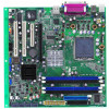
P5MT-C specifications summary CPU Chipset Front Side Bus Memory Expansion slots Storage Graphics Dual LAN USB Special features BIOS features LGA775 socket for Intel® Pentium®4/processor Compatible with Intel® PCG 05B/05A and 04B/04A and the latest Intel® Smith&#... specifications Intel ICH7R Southbridge supports: - 8 USB 2.0 ports (two on the rear panel, three connectors on the mid-borad for up to 6 additional ports) ASUS Q-Fan ASUS CrashFree BIOS 2 ASUS MyLogo2 AMI BIOS, 8 MB FWH, Green, PnP, DMI, SMBIOS 2.3, ACPI 2.0a (continued on the next page) xi
P5MT-C specifications summary CPU Chipset Front Side Bus Memory Expansion slots Storage Graphics Dual LAN USB Special features BIOS features LGA775 socket for Intel® Pentium®4/processor Compatible with Intel® PCG 05B/05A and 04B/04A and the latest Intel® Smith&#... specifications Intel ICH7R Southbridge supports: - 8 USB 2.0 ports (two on the rear panel, three connectors on the mid-borad for up to 6 additional ports) ASUS Q-Fan ASUS CrashFree BIOS 2 ASUS MyLogo2 AMI BIOS, 8 MB FWH, Green, PnP, DMI, SMBIOS 2.3, ACPI 2.0a (continued on the next page) xi
User Manual
Page 18
...for details. 1.3.2 Innovative ASUS features CrashFree BIOS 2 This feature allows you to restore the original BIOS data from the support CD in the motherboard allows you to personalize and add style to your system with customizable boot logos. ASUS Smart Fan technology The ASUS Smart Fan technology smartly ...adjusts the fan speeds according to the system loading to buy a replacement ROM chip. ASUS MyLogo2™ This new feature present in case when the BIOS codes and data are corrupted. See page 4-5 for details. See page 4-31 for details. 1-4 Chapter 1: ...
...for details. 1.3.2 Innovative ASUS features CrashFree BIOS 2 This feature allows you to restore the original BIOS data from the support CD in the motherboard allows you to personalize and add style to your system with customizable boot logos. ASUS Smart Fan technology The ASUS Smart Fan technology smartly ...adjusts the fan speeds according to the system loading to buy a replacement ROM chip. ASUS MyLogo2™ This new feature present in case when the BIOS codes and data are corrupted. See page 4-5 for details. See page 4-31 for details. 1-4 Chapter 1: ...

User Manual
Page 23
...KBPWR1 T: Mouse B: Keyboard USBPW12 USB12 REAR_FAN1 COM1 REAR_FAN2 ATXPWR1 CPU_FAN2 FM_CPU2 Intel E7230 ATX12V1 ATX12V2 CPU_FAN1 FM_CPU1 LGA775 PARALLEL PORT ® P5MT-C VGA1 LAN_EN1 LAN1 Broadcom BCM5753 LAN2 DDR2 DIMM_A1 (64 bit,240-pin module) DDR2 DIMM_A2 (64 bit,240-pin module) DDR2...PCI1 FRNT_FAN1 Intel ICH7R SATA4 SATA3 SATA2 SATA1 FRNT_FAN2 PCI2 ATI RAGE XL VGA Controller VGA_EN1 PCI3 PCI4 SB_PWR1 8Mbit Flash BIOS PCI5 TRPWR1 BPSMB1 RECOVERY1 HDLED1 COM2 Super I/O RAID_SEL1 USB56 CHASSIS1 USBPW56 CLRTC1 USBPW78 CR2032 3V Lithium Cell CMOS Power ...
...KBPWR1 T: Mouse B: Keyboard USBPW12 USB12 REAR_FAN1 COM1 REAR_FAN2 ATXPWR1 CPU_FAN2 FM_CPU2 Intel E7230 ATX12V1 ATX12V2 CPU_FAN1 FM_CPU1 LGA775 PARALLEL PORT ® P5MT-C VGA1 LAN_EN1 LAN1 Broadcom BCM5753 LAN2 DDR2 DIMM_A1 (64 bit,240-pin module) DDR2 DIMM_A2 (64 bit,240-pin module) DDR2...PCI1 FRNT_FAN1 Intel ICH7R SATA4 SATA3 SATA2 SATA1 FRNT_FAN2 PCI2 ATI RAGE XL VGA Controller VGA_EN1 PCI3 PCI4 SB_PWR1 8Mbit Flash BIOS PCI5 TRPWR1 BPSMB1 RECOVERY1 HDLED1 COM2 Super I/O RAID_SEL1 USB56 CHASSIS1 USBPW56 CLRTC1 USBPW78 CR2032 3V Lithium Cell CMOS Power ...

User Manual
Page 24
... fan pin selection (3-pin FM_CPU1, FM_CPU2) 3. RAID controller selection (3-pin RAID_SEL1) 8. PS/2 keyboard port (purple) 4. USB device wake-up (3-pin USBPW12, USBPW34, USBPW56, USBPW78) 4. Force BIOS recovery setting (3-pin RECOVERY1) Page 2-18 2-19 2-19 2-20 2-20 2-21 2-21 2-22 Rear panel connectors 1. Serial (COM1) port 6.
... fan pin selection (3-pin FM_CPU1, FM_CPU2) 3. RAID controller selection (3-pin RAID_SEL1) 8. PS/2 keyboard port (purple) 4. USB device wake-up (3-pin USBPW12, USBPW34, USBPW56, USBPW78) 4. Force BIOS recovery setting (3-pin RECOVERY1) Page 2-18 2-19 2-19 2-20 2-20 2-21 2-21 2-22 Rear panel connectors 1. Serial (COM1) port 6.

User Manual
Page 35
...expansion cards. Before installing the expansion card, read the documentation that you intend to the tables on the system and change the necessary BIOS settings, if any. Assign an IRQ to unplug the power cord before adding or removing expansion cards. Install the software drivers for later...firmly until the card is already installed in a chassis). 3. See Chapter 4 for information on the next page for the card. 2. ASUS P5MT-C 2-15 Remove the bracket opposite the slot that came with the screw you removed earlier. 6. The following sub-sections describe the slots and the...
...expansion cards. Before installing the expansion card, read the documentation that you intend to the tables on the system and change the necessary BIOS settings, if any. Assign an IRQ to unplug the power cord before adding or removing expansion cards. Install the software drivers for later...firmly until the card is already installed in a chassis). 3. See Chapter 4 for information on the next page for the card. 2. ASUS P5MT-C 2-15 Remove the bracket opposite the slot that came with the screw you removed earlier. 6. The following sub-sections describe the slots and the...

User Manual
Page 38
... 1-2 (default) to re-enter data. Plug the power cord and turn ON the computer. 6. Removing the cap will cause system boot failure! ® P5MT-C 2 P5MT-C Clear RTC RAM CLRTC1 12 23 Normal (Default) Clear CMOS 2-18 Chapter 2: Hardware information You can clear the CMOS memory of date, time, and system... setup parameters by erasing the CMOS RTC RAM data. Re-install the battery. 5. Hold down the key during the boot process and enter BIOS setup to pins 2-3. Except when clearing the RTC RAM, never remove the cap on pins 2-3 for about 5~10 seconds, then move the cap back...
... 1-2 (default) to re-enter data. Plug the power cord and turn ON the computer. 6. Removing the cap will cause system boot failure! ® P5MT-C 2 P5MT-C Clear RTC RAM CLRTC1 12 23 Normal (Default) Clear CMOS 2-18 Chapter 2: Hardware information You can clear the CMOS memory of date, time, and system... setup parameters by erasing the CMOS RTC RAM data. Re-install the battery. 5. Hold down the key during the boot process and enter BIOS setup to pins 2-3. Except when clearing the RTC RAM, never remove the cap on pins 2-3 for about 5~10 seconds, then move the cap back...

User Manual
Page 40
... VGA controller. VGA controller setting (3-pin VGA_EN1) These jumpers allow you press a key on the +5VSB lead, and a corresponding setting in the BIOS. KBPWR1 12 23 ® P5MT-C +5V +5VSB 2 (Default) P5MT-C Keyboard Power Setting 5. Set this jumper to pins 2-3 (+5VSB) to wake up feature. Keyboard power (3-pin KBPWR1) This jumper allows you...
... VGA controller. VGA controller setting (3-pin VGA_EN1) These jumpers allow you press a key on the +5VSB lead, and a corresponding setting in the BIOS. KBPWR1 12 23 ® P5MT-C +5V +5VSB 2 (Default) P5MT-C Keyboard Power Setting 5. Set this jumper to pins 2-3 (+5VSB) to wake up feature. Keyboard power (3-pin KBPWR1) This jumper allows you...

User Manual
Page 42
.... 2. Set the jumper back to quickly update or recover the original BIOS when it gets corrupted. Force BIOS recovery setting (3-pin RECOVERY1) This jumper allows you to pins 1-2. 6. Insert the floppy disk then turn on the system. ® P5MT-C RECOVERY1 2 1 2 2 3 Normal (Default) BIOS recovery P5MT-C BIOS Recovery Setting 2-22 Chapter 2: Hardware information 8. To update the...
.... 2. Set the jumper back to quickly update or recover the original BIOS when it gets corrupted. Force BIOS recovery setting (3-pin RECOVERY1) This jumper allows you to pins 1-2. 6. Insert the floppy disk then turn on the system. ® P5MT-C RECOVERY1 2 1 2 2 3 Normal (Default) BIOS recovery P5MT-C BIOS Recovery Setting 2-22 Chapter 2: Hardware information 8. To update the...

User Manual
Page 45
... 2003 before using these connectors. Serial ATA hard disk drive connection Connector SATA1/SATA2 SATA3/SATA4 Setting Master Slave Use Boot disk Data disk ASUS P5MT-C 2-25 In Standard IDE mode, you can connect Serial ATA boot/data hard disk drives to these connectors, set the Configure... 2000/2003. • Use only two Serial ATA RAID connectors for Serial ATA hard disk drives. These connectors are using the connectors in the BIOS to the SATA1 or SATA2 connector. 3. Serial ATA connectors (7-pin SATA1, SATA2, SATA3, SATA4) These connectors are for the Serial ATA signal ...
... 2003 before using these connectors. Serial ATA hard disk drive connection Connector SATA1/SATA2 SATA3/SATA4 Setting Master Slave Use Boot disk Data disk ASUS P5MT-C 2-25 In Standard IDE mode, you can connect Serial ATA boot/data hard disk drives to these connectors, set the Configure... 2000/2003. • Use only two Serial ATA RAID connectors for Serial ATA hard disk drives. These connectors are using the connectors in the BIOS to the SATA1 or SATA2 connector. 3. Serial ATA connectors (7-pin SATA1, SATA2, SATA3, SATA4) These connectors are for the Serial ATA signal ...

User Manual
Page 50
Connect the chassis power LED cable to this connector. The speaker allows you turn on the BIOS settings. The system power LED lights up or flashes when data is read from or written to hear system beeps and warnings. • ATX ... blinks when the system is in sleep mode. • Hard disk drive activity LED (Red 2-pin IDE_LED) This 2-pin connector is for easy connection. ® P5MT-C +5V NC FP_PLED +3VSB FP_MLED NC +5V GND GND SPEAKER FP_ HDLED+ GND FP_ NMIBTN# GND POWERBTN# GND NC RESETBTN# GND 2-30 Chapter 2: Hardware information...
Connect the chassis power LED cable to this connector. The speaker allows you turn on the BIOS settings. The system power LED lights up or flashes when data is read from or written to hear system beeps and warnings. • ATX ... blinks when the system is in sleep mode. • Hard disk drive activity LED (Red 2-pin IDE_LED) This 2-pin connector is for easy connection. ® P5MT-C +5V NC FP_PLED +3VSB FP_MLED NC +5V GND GND SPEAKER FP_ HDLED+ GND FP_ NMIBTN# GND POWERBTN# GND NC RESETBTN# GND 2-30 Chapter 2: Hardware information...

User Manual
Page 53
... your retailer for the first time 1. If you do not see anything within 30 seconds from the time you press the ATX power button. ASUS P5MT-C 3-1 3.1 Starting up for assistance. Connect the power cord to the power connector at the back of the system chassis. 4. After applying power, the...system power LED on the system front panel case lights up or switch between orange and green after the system LED turns on. AMI BIOS beep codes Beep Description One beep Two continuous beeps followed by two short beeps Two continuous beeps followed by four short beeps Error Keyboard ...
... your retailer for the first time 1. If you do not see anything within 30 seconds from the time you press the ATX power button. ASUS P5MT-C 3-1 3.1 Starting up for assistance. Connect the power cord to the power connector at the back of the system chassis. 4. After applying power, the...system power LED on the system front panel case lights up or switch between orange and green after the system LED turns on. AMI BIOS beep codes Beep Description One beep Two continuous beeps followed by two short beeps Two continuous beeps followed by four short beeps Error Keyboard ...

User Manual
Page 54
... the OK button to section "4.5 Power Menu" in Chapter 4 for less than four seconds lets the system enter the soft-off mode regardless of the BIOS setting. If you are using Windows® Server 2000: 1. The power supply should turn off mode, depending on the...
... the OK button to section "4.5 Power Menu" in Chapter 4 for less than four seconds lets the system enter the soft-off mode regardless of the BIOS setting. If you are using Windows® Server 2000: 1. The power supply should turn off mode, depending on the...

User Manual
Page 55
Detailed descriptions of the BIOS parameters are also provided. 4 BIOS setup This chapter tells how to change the system settings through the BIOS Setup menus.
Detailed descriptions of the BIOS parameters are also provided. 4 BIOS setup This chapter tells how to change the system settings through the BIOS Setup menus.

User Manual
Page 56
Chapter summary 4 4.1 Managing and updating your BIOS 4-1 4.2 BIOS setup program 4-10 4.3 Main menu 4-13 4.4 Advanced menu 4-18 4.5 Power menu 4-26 4.6 Boot menu 4-30 4.7 Exit menu 4-34 ASUS P5MT-C
Chapter summary 4 4.1 Managing and updating your BIOS 4-1 4.2 BIOS setup program 4-10 4.3 Main menu 4-13 4.4 Advanced menu 4-18 4.5 Power menu 4-26 4.6 Boot menu 4-30 4.7 Exit menu 4-34 ASUS P5MT-C

User Manual
Page 57
... of the following utilities allow you need to create a bootable floppy disk. ASUS P5MT-C 4-1 b. b. Do either one of boot disks for details on these utilities. 4.1 Managing and updating your optical drive letter. Copy the original motherboard BIOS using the ASUS Update or AFUDOS utilities. 4.1.1 Creating a bootable floppy disk 1. DOS environment a. Insert a 1.44 MB...
... of the following utilities allow you need to create a bootable floppy disk. ASUS P5MT-C 4-1 b. b. Do either one of boot disks for details on these utilities. 4.1 Managing and updating your optical drive letter. Copy the original motherboard BIOS using the ASUS Update or AFUDOS utilities. 4.1.1 Creating a bootable floppy disk 1. DOS environment a. Insert a 1.44 MB...

User Manual
Page 58
...as shown. 1. A:\>afudos /oOLDBIOS1.rom Main filename Extension name 3. Press . The actual BIOS screen displays may not be same as backup when the BIOS fails or gets corrupted during the updating process. Version 1.19(ASUS V2.07(03.11.24BB)) Copyright (C) 2002 American Megatrends, Inc. 4.1.2 AFUDOS utility The... AFUDOS utility allows you to update the BIOS file in DOS mode, then ...
...as shown. 1. A:\>afudos /oOLDBIOS1.rom Main filename Extension name 3. Press . The actual BIOS screen displays may not be same as backup when the BIOS fails or gets corrupted during the updating process. Version 1.19(ASUS V2.07(03.11.24BB)) Copyright (C) 2002 American Megatrends, Inc. 4.1.2 AFUDOS utility The... AFUDOS utility allows you to update the BIOS file in DOS mode, then ...

User Manual
Page 59
You need to prevent system boot failure! A:\>afudos /iP5MT-C.ROM /pbnc AMI Firmware Update Utility - WARNING!! ASUS P5MT-C 4-3 Save the BIOS file to the bootable floppy disk you created earlier. 3. Copy the AFUDOS utility (afudos.exe) from the motherboard ...verifies the file and starts updating the BIOS. All rights reserved. Visit the ASUS website (www.asus.com) and download the latest BIOS file for the motherboard. done Reading flash ...... Erasing flash ...... Write the BIOS filename on the bootable floppy disk. Boot...
You need to prevent system boot failure! A:\>afudos /iP5MT-C.ROM /pbnc AMI Firmware Update Utility - WARNING!! ASUS P5MT-C 4-3 Save the BIOS file to the bootable floppy disk you created earlier. 3. Copy the AFUDOS utility (afudos.exe) from the motherboard ...verifies the file and starts updating the BIOS. All rights reserved. Visit the ASUS website (www.asus.com) and download the latest BIOS file for the motherboard. done Reading flash ...... Erasing flash ...... Write the BIOS filename on the bootable floppy disk. Boot...


