
User Guide
Page 5
... Remote Access Configuration 4-21 4.4.4 CPU Configuration 4-22 4.4.5 Chipset Configuration 4-23 4.4.6 Onboard Devices Configuration 4-25 4.4.7 PCI PnP 4-26 4.5 Power Configuration 4-27 4.5.2 Hardware Monitor 4-29 4.6 Boot menu 4-31 4.6.1 Boot Device Priority 4-31 4.6.2 Boot Settings Configuration 4-32 4.6.3 Security 4-33 4.7 Exit menu 4-36 Chapter 5: RAID configuration 5.1 RAID configurations 5-1 5.1.1 RAID definitions 5-1 5.1.2 Installing Serial ATA hard disks 5-2 5.1.3 Setting the RAID item in BIOS 5-2 5.1.4 RAID configuration utility 5-2 5.2 Marvel® 88SE6145 RAID BIOS...
... Remote Access Configuration 4-21 4.4.4 CPU Configuration 4-22 4.4.5 Chipset Configuration 4-23 4.4.6 Onboard Devices Configuration 4-25 4.4.7 PCI PnP 4-26 4.5 Power Configuration 4-27 4.5.2 Hardware Monitor 4-29 4.6 Boot menu 4-31 4.6.1 Boot Device Priority 4-31 4.6.2 Boot Settings Configuration 4-32 4.6.3 Security 4-33 4.7 Exit menu 4-36 Chapter 5: RAID configuration 5.1 RAID configurations 5-1 5.1.1 RAID definitions 5-1 5.1.2 Installing Serial ATA hard disks 5-2 5.1.3 Setting the RAID item in BIOS 5-2 5.1.4 RAID configuration utility 5-2 5.2 Marvel® 88SE6145 RAID BIOS...

User Guide
Page 20
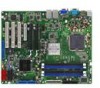
.... Temperature, fan, and voltage monitoring The CPU temperature is monitored by the Intel® ICH7R. Serial ATA II technology The motherboard supports the Serial ATA II technology through the Serial ATA interfaces controlled by the ASIC (integrated in SATA RAID solution The Intel® ICH7R allows RAID 0, RAID 1, RAID 10, and RAID 5 configuration for timely failure detection. See page 2‑26 and Chapter 5 for details. USB 2.0 is monitored for SATA hard disk drives via the Intel® Matrix Storage Manager (under Windows Operating...
.... Temperature, fan, and voltage monitoring The CPU temperature is monitored by the Intel® ICH7R. Serial ATA II technology The motherboard supports the Serial ATA II technology through the Serial ATA interfaces controlled by the ASIC (integrated in SATA RAID solution The Intel® ICH7R allows RAID 0, RAID 1, RAID 10, and RAID 5 configuration for timely failure detection. See page 2‑26 and Chapter 5 for details. USB 2.0 is monitored for SATA hard disk drives via the Intel® Matrix Storage Manager (under Windows Operating...

User Guide
Page 39
... prevent installation on the ASUS web site. • When installing one or two DIMMs, install the DIMM(s) to the blue slots (DIMM_A2/DIMM_B2). • Three DDR2 DIMMs intalled into the DIMM sockets. • Always install DIMMs with four Double Data Rate 2 (DDR2) Dual Inline Memory Modules (DIMM) sockets. The figure illustrates the location of the DDR2 DIMM sockets: DIMM_A1 DIMM_A2 DIMM_B1 DIMM_B2 112 Pins ® 128 Pins P5M2P-E/4L P5M2P-E/4L...
... prevent installation on the ASUS web site. • When installing one or two DIMMs, install the DIMM(s) to the blue slots (DIMM_A2/DIMM_B2). • Three DDR2 DIMMs intalled into the DIMM sockets. • Always install DIMMs with four Double Data Rate 2 (DDR2) Dual Inline Memory Modules (DIMM) sockets. The figure illustrates the location of the DDR2 DIMM sockets: DIMM_A1 DIMM_A2 DIMM_B1 DIMM_B2 112 Pins ® 128 Pins P5M2P-E/4L P5M2P-E/4L...
User Guide
Page 42
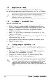
... the drivers support "Share IRQ" or that they support. Keep the screw for details. 2-18 Chapter 2: Hardware information Replace the system cover. 2.5.2 Configuring an expansion card After installing the expansion card, configure it and make the necessary hardware settings for information on the next page for later use . Refer to the tables on the system and change the necessary BIOS settings, if any. Refer to the table on BIOS setup. 2. 2.5 Expansion slots In...
... the drivers support "Share IRQ" or that they support. Keep the screw for details. 2-18 Chapter 2: Hardware information Replace the system cover. 2.5.2 Configuring an expansion card After installing the expansion card, configure it and make the necessary hardware settings for information on the next page for later use . Refer to the tables on the system and change the necessary BIOS settings, if any. Refer to the table on BIOS setup. 2. 2.5 Expansion slots In...

User Guide
Page 52
... 100/66 IDE devices. 2-28 Chapter 2: Hardware information This prevents incorrect insertion when you must configure the second drive as a slave device by setting its jumper accordingly. If you install two hard disk drives, you connect the IDE cable. • Use the 80-conductor IDE cable for an Ultra DMA 100/66 signal cable. ICH7R primary IDE connector (40-1 pin PRI_IDE1) This connector is removed to the hard disk documentation for an...
... 100/66 IDE devices. 2-28 Chapter 2: Hardware information This prevents incorrect insertion when you must configure the second drive as a slave device by setting its jumper accordingly. If you install two hard disk drives, you connect the IDE cable. • Use the 80-conductor IDE cable for an Ultra DMA 100/66 signal cable. ICH7R primary IDE connector (40-1 pin PRI_IDE1) This connector is removed to the hard disk documentation for an...

User Guide
Page 53
...-E/4L and P5M2P-E/4L, RAID_SATA1, RAID_ SATA2, RAID_SATA3, RAID_SATA4) These connectors are set IDE mode by default. 3. If you installed Serial ATA hard disk drives, you can connect Serial ATA boot/data hard disk drives to these connectors, set using the LSI MegaRAID® utility embedded in the BIOS to create a Serial ATA RAID set the Configure SATA as item in the Intel® ICH7R Southbridge. These connectors are for the Serial ATA signal cables for Serial ATA hard disk drives. In IDE mode, you intend to [RAID...
...-E/4L and P5M2P-E/4L, RAID_SATA1, RAID_ SATA2, RAID_SATA3, RAID_SATA4) These connectors are set IDE mode by default. 3. If you installed Serial ATA hard disk drives, you can connect Serial ATA boot/data hard disk drives to these connectors, set using the LSI MegaRAID® utility embedded in the BIOS to create a Serial ATA RAID set the Configure SATA as item in the Intel® ICH7R Southbridge. These connectors are for the Serial ATA signal cables for Serial ATA hard disk drives. In IDE mode, you intend to [RAID...

User Guide
Page 80
... 4: BIOS setup There is either a ZIP, LS-120, or MO drive. Configuration options: [Not Installed] [Auto] [CDROM] [ARMD] LBA/Large Mode [Auto] Enables or disables the LBA mode. These items show N/A if no IDE device is installed in the system. Select [CDROM] if you are not user-configurable. When set to [Auto], the data transfer from and to [Auto] enables the LBA mode if the device supports this mode, and...
... 4: BIOS setup There is either a ZIP, LS-120, or MO drive. Configuration options: [Not Installed] [Auto] [CDROM] [ARMD] LBA/Large Mode [Auto] Enables or disables the LBA mode. These items show N/A if no IDE device is installed in the system. Select [CDROM] if you are not user-configurable. When set to [Auto], the data transfer from and to [Auto] enables the LBA mode if the device supports this mode, and...

User Guide
Page 81
... [Enabled] Enables or disables 32-bit data transfer. Main IDE Configuration BIOS SETUP UTILITY Configure SATA as Parallel ATA physical storage devices, set or change the configurations for the Serial ATA connectors supported by the Southbridge chip. Set [Enhanced Mode] when Native OS (i.e. WIN ME, 98, NT4.0, MS DOS)is used . Select an item then press if you want to use the Serial ATA hard disk drives as [Standard IDE] Onboard IDE Operate Mode [Enhanced Mode] Enhanced Mode Support On [S-ATA] IDE Detect...
... [Enabled] Enables or disables 32-bit data transfer. Main IDE Configuration BIOS SETUP UTILITY Configure SATA as Parallel ATA physical storage devices, set or change the configurations for the Serial ATA connectors supported by the Southbridge chip. Set [Enhanced Mode] when Native OS (i.e. WIN ME, 98, NT4.0, MS DOS)is used . Select an item then press if you want to use the Serial ATA hard disk drives as [Standard IDE] Onboard IDE Operate Mode [Enhanced Mode] Enhanced Mode Support On [S-ATA] IDE Detect...

User Guide
Page 82
... the onboard IDE operation mode depending on random workloads by allowing the drive to internally optimize the order of commands. Configuration options: [Disabled] [Enabled] 4-16 Chapter 4: BIOS setup For details on how to set this item is set to Native mode when this item to [AHCI]. Configuration options: [Disabled] [Enabled] AHCI Port 3 Interlock Switch [Disabled] Allows you want the Serial ATA hard disk drives to use or configure the SATA connectors under SuSE Linux Enterprise Server 9.0 SP1 operating system environment.
... the onboard IDE operation mode depending on random workloads by allowing the drive to internally optimize the order of commands. Configuration options: [Disabled] [Enabled] 4-16 Chapter 4: BIOS setup For details on how to set this item is set to Native mode when this item to [AHCI]. Configuration options: [Disabled] [Enabled] AHCI Port 3 Interlock Switch [Disabled] Allows you want the Serial ATA hard disk drives to use or configure the SATA connectors under SuSE Linux Enterprise Server 9.0 SP1 operating system environment.

User Guide
Page 84
... USB Ports] [4 USB Ports] 4-18 Chapter 4: BIOS setup 4.4 Advanced menu The Advanced menu items allow you to enable a specific number of the Advanced menu items. Incorrect field values can cause the system to change the settings for the CPU and other system devices. Main Advanced BIOS SETUP UTILITY Power Boot Exit USB Configuration MPS Configuration Remote Access Configuration CPU Configuration Chipset Onboard Devices Configuration PCIPnP Configure the MultiProcessor Table. USB Devices Enabled: None USB Function Legacy USB Support USB2.0 Controller USB2.0 Controller Mode BIOS...
... USB Ports] [4 USB Ports] 4-18 Chapter 4: BIOS setup 4.4 Advanced menu The Advanced menu items allow you to enable a specific number of the Advanced menu items. Incorrect field values can cause the system to change the settings for the CPU and other system devices. Main Advanced BIOS SETUP UTILITY Power Boot Exit USB Configuration MPS Configuration Remote Access Configuration CPU Configuration Chipset Onboard Devices Configuration PCIPnP Configure the MultiProcessor Table. USB Devices Enabled: None USB Function Legacy USB Support USB2.0 Controller USB2.0 Controller Mode BIOS...
User Guide
Page 85
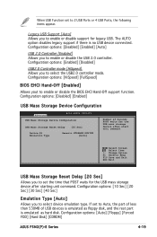
...: [Disabled] [Enabled] USB Mass Storage Device Configuration Advanced BIOS SETUP UTILITY USB Mass Storage Device Configuration USB Mass Storage Reset Delay [20 Sec] Device #1 Emulation Type Generic STORAGE DEVICE [Auto] Number of USB devices is emulated as hard disk. Select Screen Select Item +- When USB Function set to Auto, the part of less than 530MB of Seconds POST waits for the USB mass storage device after starting unit command. Configuration options: [Auto] [Floppy] [Forced FDD] [Hard Disk] [CDROM] ASUS P5M2(P)-E Series 4-19 The AUTO option disables legacy support if...
...: [Disabled] [Enabled] USB Mass Storage Device Configuration Advanced BIOS SETUP UTILITY USB Mass Storage Device Configuration USB Mass Storage Reset Delay [20 Sec] Device #1 Emulation Type Generic STORAGE DEVICE [Auto] Number of USB devices is emulated as hard disk. Select Screen Select Item +- When USB Function set to Auto, the part of less than 530MB of Seconds POST waits for the USB mass storage device after starting unit command. Configuration options: [Auto] [Floppy] [Forced FDD] [Hard Disk] [CDROM] ASUS P5M2(P)-E Series 4-19 The AUTO option disables legacy support if...

User Guide
Page 87
... a serial port mode. Configuration options: [None] [Hardware] [Software] Redirection After BIOS POST [Always] Sets the redirection mode after the BIOS Power-On Self-Test (POST). Some operating systems may not work when this menu allows you to select a serial port for console redirection. Remote Access Serial port number Base Address, IRQ Serial Port Mode Flow Control Redirection After BIOS POST Terminal Type VT-UTF8 Combo Key Support [Enabled] [COM1] [3F8h,4] [115200 8, n,1] [None] [Always] [ANSI] [Enabled] Select Screen Select Item +- Configuration options: [Disabled] [Enabled] The...
... a serial port mode. Configuration options: [None] [Hardware] [Software] Redirection After BIOS POST [Always] Sets the redirection mode after the BIOS Power-On Self-Test (POST). Some operating systems may not work when this menu allows you to select a serial port for console redirection. Remote Access Serial port number Base Address, IRQ Serial Port Mode Flow Control Redirection After BIOS POST Terminal Type VT-UTF8 Combo Key Support [Enabled] [COM1] [3F8h,4] [115200 8, n,1] [None] [Always] [ANSI] [Enabled] Select Screen Select Item +- Configuration options: [Disabled] [Enabled] The...

User Guide
Page 89
... to change the advanced chipset settings. Select an item then press to enable or disable the CPU speed. ASUS P5M2(P)-E Series 4-23 Configuration options: [Auto] [533 MHz] [667 MHz] Configure DRAM Timing by SPD Spread Spectrum VGA Priority Order [Disabled] [PCIE-OBVGA) PCIE LAN-8056A PCIE LAN-8056B PCIE LAN-8056C PCIE LAN-8056D LAN8056 Boot ROM PCIE Marvell-6145 SATA6145 RAID ROM PEG Port Configuration PEG Port PEG Port VCI Map PEG Force x1 Memory Remap Feature [Enabled] [Enabled] [Enabled] [Enabled] [Disabled] [Enabled] [Enabled] [Enabled] [TC7] [Disabled] [Enabled...
... to change the advanced chipset settings. Select an item then press to enable or disable the CPU speed. ASUS P5M2(P)-E Series 4-23 Configuration options: [Auto] [533 MHz] [667 MHz] Configure DRAM Timing by SPD Spread Spectrum VGA Priority Order [Disabled] [PCIE-OBVGA) PCIE LAN-8056A PCIE LAN-8056B PCIE LAN-8056C PCIE LAN-8056D LAN8056 Boot ROM PCIE Marvell-6145 SATA6145 RAID ROM PEG Port Configuration PEG Port PEG Port VCI Map PEG Force x1 Memory Remap Feature [Enabled] [Enabled] [Enabled] [Enabled] [Disabled] [Enabled] [Enabled] [Enabled] [TC7] [Disabled] [Enabled...

User Guide
Page 91
... PCI Express Graphic port. Advanced BIOS SETUP UTILITY Configure Win83627EHG-A Super IO Chipset Serial Port1 Address Serial Port2 Address Serial Port2 Mode [3F8/IRQ4] [2F8/IRQ3] [Normal] Allows BIOS to [Enabled]. Configuration options: [Enabled] [Disabled] The following items appear only when the PEG Port item is set the PEG Port VC1 Map. Configuration options: [Disabled] [Enabled] Disable this item if you are using RedHat Linux Advanced Server 3.0 UP5/UP6 operating system. 4.4.6 Onboard Devices Configuration The Onboard Devices Configuration menu allows you to change...
... PCI Express Graphic port. Advanced BIOS SETUP UTILITY Configure Win83627EHG-A Super IO Chipset Serial Port1 Address Serial Port2 Address Serial Port2 Mode [3F8/IRQ4] [2F8/IRQ3] [Normal] Allows BIOS to [Enabled]. Configuration options: [Enabled] [Disabled] The following items appear only when the PEG Port item is set the PEG Port VC1 Map. Configuration options: [Disabled] [Enabled] Disable this item if you are using RedHat Linux Advanced Server 3.0 UP5/UP6 operating system. 4.4.6 Onboard Devices Configuration The Onboard Devices Configuration menu allows you to change...

User Guide
Page 93
... the RSDT pointer list. Select Screen Select Item +- When set to [Yes], BIOS assigns an IRQ to PCI VGA card if the card requests for the ACPI and Advanced Power Management (APM) features. Main Advanced BIOS SETUP UTILITY Power Boot Exit ACPI 2.0 Support ACPI APIC Support [Disabled] [Enabled] APM Configuration Hardware Monitor Add additional tables as per ACPI 2.0 specifications. Configuration options: [PCI Device] [Reserved] 4.5 Power Configuration The Power Configuration menu items allow you to change the settings for an IRQ. Change Option F1...
... the RSDT pointer list. Select Screen Select Item +- When set to [Yes], BIOS assigns an IRQ to PCI VGA card if the card requests for the ACPI and Advanced Power Management (APM) features. Main Advanced BIOS SETUP UTILITY Power Boot Exit ACPI 2.0 Support ACPI APIC Support [Disabled] [Enabled] APM Configuration Hardware Monitor Add additional tables as per ACPI 2.0 specifications. Configuration options: [PCI Device] [Reserved] 4.5 Power Configuration The Power Configuration menu items allow you to change the settings for an IRQ. Change Option F1...

User Guide
Page 95
... Monitor Hardware Monitor CPU Temperature MB Temperature [60.5ºC/140.5ºF] [32ºC/89.5ºF] CPU1 Temperature CPU Fan Speed CPU Smart Fan Control Front1 Fan Speed Front2 Fan Speed Front3 Fan Speed Rear1 Fan Speed VCORE Voltage 3.3V Voltage 5V Voltage 12V Voltage VBAT Voltage 3VSB Voltage [2884RPM] [Disabled] [N/A] [N/A] [N/A] [N/A] [1.296V] [3.248V] [5.120V] [12.091V] [3.248V] [3.248V] v02.58 (C)Copyright 1985-2007, American Megatrends, Inc. This Feature requires an ATX power supply that appears below shows the default Not Installed. After you have set a password...
... Monitor Hardware Monitor CPU Temperature MB Temperature [60.5ºC/140.5ºF] [32ºC/89.5ºF] CPU1 Temperature CPU Fan Speed CPU Smart Fan Control Front1 Fan Speed Front2 Fan Speed Front3 Fan Speed Rear1 Fan Speed VCORE Voltage 3.3V Voltage 5V Voltage 12V Voltage VBAT Voltage 3VSB Voltage [2884RPM] [Disabled] [N/A] [N/A] [N/A] [N/A] [1.296V] [3.248V] [5.120V] [12.091V] [3.248V] [3.248V] v02.58 (C)Copyright 1985-2007, American Megatrends, Inc. This Feature requires an ATX power supply that appears below shows the default Not Installed. After you have set a password...

User Guide
Page 98
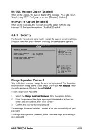
... use the ASUS MyLogo2™ feature. Configuration options: [Disabled] [Enabled] Set this item allows the BIOS to Enabled, the system waits for PS/2 mouse. Configuration options: [Disabled] [Enabled] 4-32 Chapter 4: BIOS setup When set to skip some power on state for optional ROM. Select Screen Select Item +- 4.6.2 Boot Settings Configuration BIOS SETUP UTILITY Boot Boot Settings Configuration Quick Boot Full Screen Logo AddOn ROM Display Mode Bootup Num-Lock PS/2 Mouse Support Wait For 'F1' If Error Hit 'DEL' Message Display Interrupt 19 Capture [Enabled] [Enabled...
... use the ASUS MyLogo2™ feature. Configuration options: [Disabled] [Enabled] Set this item allows the BIOS to Enabled, the system waits for PS/2 mouse. Configuration options: [Disabled] [Enabled] 4-32 Chapter 4: BIOS setup When set to skip some power on state for optional ROM. Select Screen Select Item +- 4.6.2 Boot Settings Configuration BIOS SETUP UTILITY Boot Boot Settings Configuration Quick Boot Full Screen Logo AddOn ROM Display Mode Bootup Num-Lock PS/2 Mouse Support Wait For 'F1' If Error Hit 'DEL' Message Display Interrupt 19 Capture [Enabled] [Enabled...
User Guide
Page 99
...BIOS SETUP UTILITY Boot Supervisor Password : Not Installed User Password : Not Installed Change Supervisor Password Change User Password to change the supervisor password. Hit 'DEL' Message Display [Enabled] When set a password, this function allows the option ROMs to trap Interrupt 19. ASUS P5M2(P)-E Series 4-33 Configuration options: [Disabled] [Enabled] 4.6.3 Security The Security menu items allow you to run Setup" during POST. After you successfully set a Supervisor Password: 1. The message "Password Installed" appears after you set to Enabled, the system displays...
...BIOS SETUP UTILITY Boot Supervisor Password : Not Installed User Password : Not Installed Change Supervisor Password Change User Password to change the supervisor password. Hit 'DEL' Message Display [Enabled] When set a password, this function allows the option ROMs to trap Interrupt 19. ASUS P5M2(P)-E Series 4-33 Configuration options: [Disabled] [Enabled] 4.6.3 Security The Security menu items allow you to run Setup" during POST. After you successfully set a Supervisor Password: 1. The message "Password Installed" appears after you set to Enabled, the system displays...

User Guide
Page 107
... required for this setup. This RAID configuration provides data protection and increases fault tolerance to read and write data in the other business systems. Use a minimum of a single disk alone, thus improving data access and storage. Use two new drives or use an existing drive and a new drive for this setup. Among the advantages of data from one drive fails, the disk array management software directs all applications to configure and IDE and Serial ATA hard disk drives as RAID sets. (For P5M2P-E/4L...
... required for this setup. This RAID configuration provides data protection and increases fault tolerance to read and write data in the other business systems. Use a minimum of a single disk alone, thus improving data access and storage. Use two new drives or use an existing drive and a new drive for this setup. Among the advantages of data from one drive fails, the disk array management software directs all applications to configure and IDE and Serial ATA hard disk drives as RAID sets. (For P5M2P-E/4L...
User Guide
Page 108
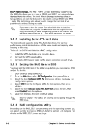
... supported by the ICHR chip allows you to the power connector on each hard disk drive to section "2.6 Jumpers" for details on entering and navigating through the BIOS Setup. 5.1.4 RAID configuration utility Depending on each drive. 5.1.3 Setting the RAID item in BIOS You must set the RAID item in a created RAID set using only two identical hard disk drives. Connect a SATA power cable to change the hard disk drive partition size without losing any data. Go to section "6.1 RAID driver installation" for a RAID configuration: 1. Refer to create a virtual RAID 0 and RAID 1 sets...
... supported by the ICHR chip allows you to the power connector on each hard disk drive to section "2.6 Jumpers" for details on entering and navigating through the BIOS Setup. 5.1.4 RAID configuration utility Depending on each drive. 5.1.3 Setting the RAID item in BIOS You must set the RAID item in a created RAID set using only two identical hard disk drives. Connect a SATA power cable to change the hard disk drive partition size without losing any data. Go to section "6.1 RAID driver installation" for a RAID configuration: 1. Refer to create a virtual RAID 0 and RAID 1 sets...


