
User Manual
Page 1
Motherboard
Motherboard

User Manual
Page 1
P5KPL SE Motherboard
P5KPL SE Motherboard
User Manual
Page 3
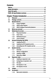
Contents Notices...vi Safety information vii About this guide vii P5KPL SE specifications summary ix Chapter 1Product introduction 1-1 1.1 Welcome 1-1 1.2 Package contents 1-1 1.3 Special features 1-1 1.3.1 Product highlights 1-1 1.3.2 ASUS unique features 1-2 1.3.3 ASUS Intelligent Overclocking features 1-3 1.4 Before you proceed 1-4 1.5 Motherboard overview 1-5 1.5.1 Placement direction 1-5 1.5.2 Screw holes 1-5 1.5.3 Motherboard layout 1-6 1.5.4 Layout contents 1-7 1.6 Central Processing Unit (CPU 1-7 1.6.1 Installing the CPU 1-8 1.6.2 Installing the CPU heatsink and...
Contents Notices...vi Safety information vii About this guide vii P5KPL SE specifications summary ix Chapter 1Product introduction 1-1 1.1 Welcome 1-1 1.2 Package contents 1-1 1.3 Special features 1-1 1.3.1 Product highlights 1-1 1.3.2 ASUS unique features 1-2 1.3.3 ASUS Intelligent Overclocking features 1-3 1.4 Before you proceed 1-4 1.5 Motherboard overview 1-5 1.5.1 Placement direction 1-5 1.5.2 Screw holes 1-5 1.5.3 Motherboard layout 1-6 1.5.4 Layout contents 1-7 1.6 Central Processing Unit (CPU 1-7 1.6.1 Installing the CPU 1-8 1.6.2 Installing the CPU heatsink and...

User Manual
Page 6
This class B digital apparatus complies with Canadian ICES-003. DO NOT throw the motherboard in municipal waste. This symbol of the crossed out wheeled bin indicates that the product (electrical and electronic equipment) should not be placed in municipal ...
This class B digital apparatus complies with Canadian ICES-003. DO NOT throw the motherboard in municipal waste. This symbol of the crossed out wheeled bin indicates that the product (electrical and electronic equipment) should not be placed in municipal ...
User Manual
Page 7
... on it by yourself. Detailed descriptions of the BIOS parameters are connected. If you are not sure about the voltage of the motherboard and the new technology it supports. • Chapter 2: BIOS setup This chapter tells how to fix it , carefully read all...Product introduction This chapter describes the features of the electrical outlet you add a device. • Before connecting or removing signal cables from the motherboard, ensure that all cables are correctly connected and the power cables are unplugged. • Seek professional assistance before using , contact your local ...
... on it by yourself. Detailed descriptions of the BIOS parameters are connected. If you are not sure about the voltage of the motherboard and the new technology it supports. • Chapter 2: BIOS setup This chapter tells how to fix it , carefully read all...Product introduction This chapter describes the features of the electrical outlet you add a device. • Before connecting or removing signal cables from the motherboard, ensure that all cables are correctly connected and the power cables are unplugged. • Seek professional assistance before using , contact your local ...
User Manual
Page 9
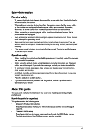
P5KPL SE specifications summary CPU. FSB tuning from 200 MHz up to 600 MHz at 1MHz increment ASUS C.P.R. (CPU Parameter Recall) ASUS Special Features ASUS CrashFree BIOS 3 ASUS Q-Fan ASUS EZ Flash 2 ASUS MyLogo 2 AI NET 2 (continued on the motherboard, the actual usable memory for the Memory QVL (Qualified Vendors Lists). 1 x PCI Express ...about 3GB or less. For effective use of memory, we recommend that you install 4GB or more memory installed on the motherboard. • Refer to the memory address limitation on 32-bit Windows OS, when you install a 64-bit Windows OS...
P5KPL SE specifications summary CPU. FSB tuning from 200 MHz up to 600 MHz at 1MHz increment ASUS C.P.R. (CPU Parameter Recall) ASUS Special Features ASUS CrashFree BIOS 3 ASUS Q-Fan ASUS EZ Flash 2 ASUS MyLogo 2 AI NET 2 (continued on the motherboard, the actual usable memory for the Memory QVL (Qualified Vendors Lists). 1 x PCI Express ...about 3GB or less. For effective use of memory, we recommend that you install 4GB or more memory installed on the motherboard. • Refer to the memory address limitation on 32-bit Windows OS, when you install a 64-bit Windows OS...
User Manual
Page 11
Before you for the following items. Motherboard Cables Accessories Application DVD Documentation ASUS P5KPL SE motherboard 1 x Serial ATA cable 1 x Ultra DMA 100/66 cable 1 x SATA power cable 1 x I/O shield ASUS motherboard support DVD User Manual If any of gaming experience and multi-... while minimizing the impact on the use of ASUS quality motherboards! LGA775 Intel® Quad-core Processor Ready This motherboard supports the latest powerful and energy efficient processors from Intel. ASUS P5KPL SE 1-1 The motherboard delivers a host of new features and latest...
Before you for the following items. Motherboard Cables Accessories Application DVD Documentation ASUS P5KPL SE motherboard 1 x Serial ATA cable 1 x Ultra DMA 100/66 cable 1 x SATA power cable 1 x I/O shield ASUS motherboard support DVD User Manual If any of gaming experience and multi-... while minimizing the impact on the use of ASUS quality motherboards! LGA775 Intel® Quad-core Processor Ready This motherboard supports the latest powerful and energy efficient processors from Intel. ASUS P5KPL SE 1-1 The motherboard delivers a host of new features and latest...
User Manual
Page 12
...standard for the early future and is designed to 12.8 GB/s (17.0 GB/s when overclocking 1066). Serial ATA 3Gb/s technology This motherboard supports hard drives based on the Serial ATA (SATA) 3Gb/s storage specifications, delivering enhanced scalability and doubling the bus bandwidth for details... features ASUS MyLogo2™ This feature allows you to install DIMMs with peak bandwidths of the latest 3D graphics, multimedia, and Internet applications. Without restriction to the memory size across the two channels, the motherboard allows you to ten times faster than conventional 10/100/...
...standard for the early future and is designed to 12.8 GB/s (17.0 GB/s when overclocking 1066). Serial ATA 3Gb/s technology This motherboard supports hard drives based on the Serial ATA (SATA) 3Gb/s storage specifications, delivering enhanced scalability and doubling the bus bandwidth for details... features ASUS MyLogo2™ This feature allows you to install DIMMs with peak bandwidths of the latest 3D graphics, multimedia, and Internet applications. Without restriction to the memory size across the two channels, the motherboard allows you to ten times faster than conventional 10/100/...
User Manual
Page 13
... data from a USB flash disk containing the BIOS file. ASUS CrashFree BIOS 3 The ASUS CrashFree BIOS 3 allows users to overclocking failure, C.P.R. With this utility, you can easily monitor the condition of the motherboard BIOS allows automatic re-setting to the BIOS default settings in...based diagnostic tool that detects and reports Ethernet cable faults and shorts. AI NET 2 AI NET 2 is a user-friendly BIOS update utility. ASUS P5KPL SE 1-3 See page 2-3 for details. During the bootup process, AI NET 2 immediately diagnoses the LAN cable and reports shorts and faults up ...
... data from a USB flash disk containing the BIOS file. ASUS CrashFree BIOS 3 The ASUS CrashFree BIOS 3 allows users to overclocking failure, C.P.R. With this utility, you can easily monitor the condition of the motherboard BIOS allows automatic re-setting to the BIOS default settings in...based diagnostic tool that detects and reports Ethernet cable faults and shorts. AI NET 2 AI NET 2 is a user-friendly BIOS update utility. ASUS P5KPL SE 1-3 See page 2-3 for details. During the bootup process, AI NET 2 immediately diagnoses the LAN cable and reports shorts and faults up ...
User Manual
Page 14
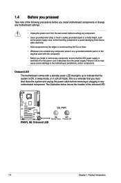
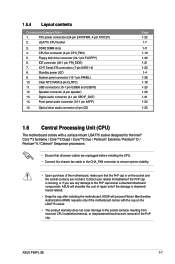
... that the ATX power supply is switched off mode. The illustration below shows the location of the following precautions before you install motherboard components or change any motherboard component. P5KPL SE SB_PWR P5KPL SE Onboard LED ON OFF Standy Power Powered Off 1-4 Chapter 1: Product introduction Failure to do so may cause severe damage to avoid touching...
... that the ATX power supply is switched off mode. The illustration below shows the location of the following precautions before you install motherboard components or change any motherboard component. P5KPL SE SB_PWR P5KPL SE Onboard LED ON OFF Standy Power Powered Off 1-4 Chapter 1: Product introduction Failure to do so may cause severe damage to avoid touching...
User Manual
Page 15
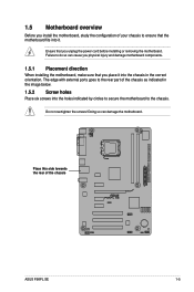
... the screws! Place this side towards. Ensure that you unplug the power cord before installing or removing the motherboard. Failure to do so can damage the motherboard. the rear of the chassis as indicated in the image below. 1.5.2 Screw holes Place six screws into ...1.5 Motherboard overview Before you install the motherboard, study the configuration of your chassis to ensure that the motherboard fits into it into the holes indicated by circles to secure the motherboard to the chassis. The edge with external ports goes to the rear part of the chassis P5KPL SE ASUS P5KPL SE 1-5...
... the screws! Place this side towards. Ensure that you unplug the power cord before installing or removing the motherboard. Failure to do so can damage the motherboard. the rear of the chassis as indicated in the image below. 1.5.2 Screw holes Place six screws into ...1.5 Motherboard overview Before you install the motherboard, study the configuration of your chassis to ensure that the motherboard fits into it into the holes indicated by circles to secure the motherboard to the chassis. The edge with external ports goes to the rear part of the chassis P5KPL SE ASUS P5KPL SE 1-5...
User Manual
Page 16
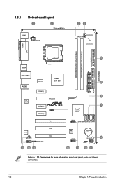
1.5.3 Motherboard layout 1 2 20.3cm(8.0in) KBMS ATX12V 34 CPU_FAN Super I/O COM1 LPT DDR2 DIMM_B1 (64bit, 240-pin module) DDR2 DIMM_A1 (64bit, 240-pin module) FLOPPY LGA775 5 USB34 30.5cm(12in) LAN1_USB12 Intel® ICS G31 B0 9LPRS954A3GLF 6 AUDIO EATXPWR PRI_IDE PCIEX1_1 1 PCIEX16 RTL 8111C P5KPL SE PCIEX1_2 7 PCIEX1_3 SPEAKER Intel® ICH7 PCI1 USB56...
1.5.3 Motherboard layout 1 2 20.3cm(8.0in) KBMS ATX12V 34 CPU_FAN Super I/O COM1 LPT DDR2 DIMM_B1 (64bit, 240-pin module) DDR2 DIMM_A1 (64bit, 240-pin module) FLOPPY LGA775 5 USB34 30.5cm(12in) LAN1_USB12 Intel® ICS G31 B0 9LPRS954A3GLF 6 AUDIO EATXPWR PRI_IDE PCIEX1_1 1 PCIEX16 RTL 8111C P5KPL SE PCIEX1_2 7 PCIEX1_3 SPEAKER Intel® ICH7 PCI1 USB56...
User Manual
Page 17
... the LGA775 socket. • The product warranty does not cover damage to the PnP cap/socket contacts/motherboard components. ATX power connectors (24-pin EATXPWR, 4-pin ATX12V) 2. IDE connector (40-1 pin PRI_EIDE) 7. Standby power LED 9. ASUS P5KPL SE 1-7 Floppy disk drive connector (34-1 pin FLOPPY) 6. Front panel audio connector (10-1 pin AAFP) 15. DDR2...
... the LGA775 socket. • The product warranty does not cover damage to the PnP cap/socket contacts/motherboard components. ATX power connectors (24-pin EATXPWR, 4-pin ATX12V) 2. IDE connector (40-1 pin PRI_EIDE) 7. Standby power LED 9. ASUS P5KPL SE 1-7 Floppy disk drive connector (34-1 pin FLOPPY) 6. Front panel audio connector (10-1 pin AAFP) 15. DDR2...
User Manual
Page 18
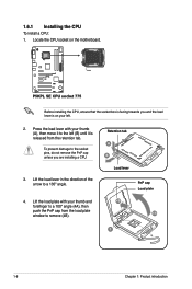
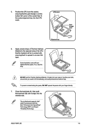
... load lever in the direction of the arrow to remove (4B). Locate the CPU socket on your thumb and forefinger to the left . 2. P5KPL SE P5KPL SE CPU socket 775 Before installing the CPU, ensure that the socket box is facing towards you are installing a CPU. 3. Lift the load plate ... a 100º angle (4A), then push the PnP cap from the retention tab. Press the load lever with your left (B) until it is on the motherboard. Retention tab A B Load lever PnP cap Load plate 4B 4A 3 1-8 Chapter 1: Product introduction 1.6.1 Installing the CPU To install a CPU: 1. To ...
... load lever in the direction of the arrow to remove (4B). Locate the CPU socket on your thumb and forefinger to the left . 2. P5KPL SE P5KPL SE CPU socket 775 Before installing the CPU, ensure that the socket box is facing towards you are installing a CPU. 3. Lift the load plate ... a 100º angle (4A), then push the PnP cap from the retention tab. Press the load lever with your left (B) until it is on the motherboard. Retention tab A B Load lever PnP cap Load plate 4B 4A 3 1-8 Chapter 1: Product introduction 1.6.1 Installing the CPU To install a CPU: 1. To ...
User Manual
Page 19
CPU notch Gold triangle mark Alignment key 6. B ASUS P5KPL SE 1-9 DO NOT eat the Thermal Interface Material. Close the load plate (A), then push the load lever (B) until it snaps into your eyes or touches your finger directly. 7. The motherboard supports Intel® LGA775 processors with , ensuring that it gets into the A retention tab. Apply several...
CPU notch Gold triangle mark Alignment key 6. B ASUS P5KPL SE 1-9 DO NOT eat the Thermal Interface Material. Close the load plate (A), then push the load lever (B) until it snaps into your eyes or touches your finger directly. 7. The motherboard supports Intel® LGA775 processors with , ensuring that it gets into the A retention tab. Apply several...
User Manual
Page 20
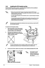
... make sure that you buy a CPU separately, ensure that you have installed the motherboard to the CPU heatsink or CPU before you fail to connect the CPU fan connector! The illustration above is for reference only. 3. P5KPL SE P5KPL SE CPU fan connector 1-10 Chapter 1: Product introduction To install the CPU heatsink and fan...place. 1.6.2 Installing the CPU heatsink and fan The Intel® LGA775 processor requires a specially designed heatsink and fan assembly to the connector on the motherboard labeled CPU_FAN. Ensure that the four fasteners B match the holes on the...
... make sure that you buy a CPU separately, ensure that you have installed the motherboard to the CPU heatsink or CPU before you fail to connect the CPU fan connector! The illustration above is for reference only. 3. P5KPL SE P5KPL SE CPU fan connector 1-10 Chapter 1: Product introduction To install the CPU heatsink and fan...place. 1.6.2 Installing the CPU heatsink and fan The Intel® LGA775 processor requires a specially designed heatsink and fan assembly to the connector on the motherboard labeled CPU_FAN. Ensure that the four fasteners B match the holes on the...
User Manual
Page 21
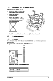
... location of the DDR2 DIMM sockets: DIMM_A1 DIMM_B1 P5KPL SE P5KPL SE 240-pin DDR2 DIMM sockets Channel Channel A Channel B Sockets DIMM_A1 DIMM_B1 ASUS P5KPL SE 1-11 Carefully remove the heatsink and fan assembly from A the connector on the motherboard. B 2. B 3. Disconnect the CPU fan cable from the motherboard. 1.7 System memory 1.7.1 Overview The motherboard comes with two Double Data Rate 2 (DDR2...
... location of the DDR2 DIMM sockets: DIMM_A1 DIMM_B1 P5KPL SE P5KPL SE 240-pin DDR2 DIMM sockets Channel Channel A Channel B Sockets DIMM_A1 DIMM_B1 ASUS P5KPL SE 1-11 Carefully remove the heatsink and fan assembly from A the connector on the motherboard. B 2. B 3. Disconnect the CPU fan cable from the motherboard. 1.7 System memory 1.7.1 Overview The motherboard comes with two Double Data Rate 2 (DDR2...

User Manual
Page 22
... 64-bit Windows OS when having 4GB or more memory on the motherboard, the actual usable memory for single-channel operation. • Always install DIMMs with the same CAS latency. P5KPL SE Motherboard Qualified Vendors Lists (QVL) DDR2-667MHz capability Size 256MB 256MB 256MB ... HYB18T5128000AF-3SSSS27416 SS HYB18T512800AF3SFSS05346 DS HYB18T512800AF3SSSS28104 SS 64M8CFEGPS0900647 DS MIII0052532M8CEC DS MID095D62864M8CEC DS Heat-Sink Package (continued on the motherboard. • This motherboard does not support DIMMs made up of 256 megabit (Mb) chips or less. Some old-version DDR2-800...
... 64-bit Windows OS when having 4GB or more memory on the motherboard, the actual usable memory for single-channel operation. • Always install DIMMs with the same CAS latency. P5KPL SE Motherboard Qualified Vendors Lists (QVL) DDR2-667MHz capability Size 256MB 256MB 256MB ... HYB18T5128000AF-3SSSS27416 SS HYB18T512800AF3SFSS05346 DS HYB18T512800AF3SSSS28104 SS 64M8CFEGPS0900647 DS MIII0052532M8CEC DS MID095D62864M8CEC DS Heat-Sink Package (continued on the motherboard. • This motherboard does not support DIMMs made up of 256 megabit (Mb) chips or less. Some old-version DDR2-800...
User Manual
Page 26
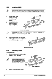
... the DIMM lightly with a notch so that it flips out with extra force. 1 2 DDR2 DIMM notch 2. Simultaneously press the retaining clips outward to both the motherboard and the components. 1. The DIMM might get damaged when it fits in place and the DIMM is keyed with your fingers when pressing the retaining...
... the DIMM lightly with a notch so that it flips out with extra force. 1 2 DDR2 DIMM notch 2. Simultaneously press the retaining clips outward to both the motherboard and the components. 1. The DIMM might get damaged when it fits in place and the DIMM is keyed with your fingers when pressing the retaining...

User Manual
Page 27
...that the drivers support "Share IRQ" or that came with the screw you physical injury and damage motherboard components. 1.8.1 Installing an expansion card To install an expansion card: 1. ASUS P5KPL SE 1-17 Before installing the expansion card, read the documentation that the cards do so may need ... When using PCI cards on the system and change the necessary BIOS settings, if any. Remove the system unit cover (if your motherboard is completely seated on the next page for later use . Align the card connector with the PCI Express specifications. Replace the system cover...
...that the drivers support "Share IRQ" or that came with the screw you physical injury and damage motherboard components. 1.8.1 Installing an expansion card To install an expansion card: 1. ASUS P5KPL SE 1-17 Before installing the expansion card, read the documentation that the cards do so may need ... When using PCI cards on the system and change the necessary BIOS settings, if any. Remove the system unit cover (if your motherboard is completely seated on the next page for later use . Align the card connector with the PCI Express specifications. Replace the system cover...


