
User Manual
Page 31
Reading flash ..... done Write to file...... BIOS 2.1 使用 AFUDOS BIOS AFUDOS DOS BIOS BIOS 程式。AFUDOS BIOS BIOS BIOS 程式 BIOS 程式。 1.2MB BIOS 1 AFUDOS 程式(afudos. ok A:\> 當 BIOS DOS 31 Version 1.19(ASUS V2.07(03.11.24BB)) Copyright (C) 2002 American Megatrends, Inc. exe 2 DOS afudos /o[filename filename A:\>afudos /oOLDBIOS1.rom 3. 按下 afudos /oOLDBIOS1.rom AMI Firmware Update Utility - All rights reserved.
Reading flash ..... done Write to file...... BIOS 2.1 使用 AFUDOS BIOS AFUDOS DOS BIOS BIOS 程式。AFUDOS BIOS BIOS BIOS 程式 BIOS 程式。 1.2MB BIOS 1 AFUDOS 程式(afudos. ok A:\> 當 BIOS DOS 31 Version 1.19(ASUS V2.07(03.11.24BB)) Copyright (C) 2002 American Megatrends, Inc. exe 2 DOS afudos /o[filename filename A:\>afudos /oOLDBIOS1.rom 3. 按下 afudos /oOLDBIOS1.rom AMI Firmware Update Utility - All rights reserved.

User Manual
Page 32
... (C) 2002 American Megatrends, Inc. Erasing flash ...... All rights reserved. done BIOS 5. 當 BIOS DOS A:\>afudos /iP5B-VM DO.ROM AMI Firmware Update Utility - 更新 BIOS 程式 AFUDOS BIOS 程式。 1 tw.asus.com BIOS 片中。 BIOS BIOS 2. 將 AFUDOS.EXE BIOS 3 DOS afudos /i[filename filename BIOS 程式。 A:\>afudos /iP5B-VM DO.ROM 4. Version...
... (C) 2002 American Megatrends, Inc. Erasing flash ...... All rights reserved. done BIOS 5. 當 BIOS DOS A:\>afudos /iP5B-VM DO.ROM AMI Firmware Update Utility - 更新 BIOS 程式 AFUDOS BIOS 程式。 1 tw.asus.com BIOS 片中。 BIOS BIOS 2. 將 AFUDOS.EXE BIOS 3 DOS afudos /i[filename filename BIOS 程式。 A:\>afudos /iP5B-VM DO.ROM 4. Version...

User Manual
Page 33
... Message: Do You Want To Save Bios (Y/N) 33 2.2 使用 AwardBIOS Flash BIOS AwardBIOS Flash AwardBIOS Flash 程式(AWDFLASH.EXE BIOS AwardBIOS Flash BIOS 程式。 1 http://tw.asus.com BIOS M2N-VM HDMI.bin FAT 32/16 格式的 USB BIOS 2 CD/DVD AwardBIOS Flash BIOS 3 DOS 4. 當 A BIOS 檔案與 AwardBIOS Flash...
... Message: Do You Want To Save Bios (Y/N) 33 2.2 使用 AwardBIOS Flash BIOS AwardBIOS Flash AwardBIOS Flash 程式(AWDFLASH.EXE BIOS AwardBIOS Flash BIOS 程式。 1 http://tw.asus.com BIOS M2N-VM HDMI.bin FAT 32/16 格式的 USB BIOS 2 CD/DVD AwardBIOS Flash BIOS 3 DOS 4. 當 A BIOS 檔案與 AwardBIOS Flash...

User Manual
Page 34
...Flash Type - OFE00 OK Write OK No Update Write Fail Warning: Don't Turn Off Power Or Reset System! 在更新 BIOS 9 Flash Complete BIOS F1 AwardBIOS Flash Utility for ASUS V1.14 (C) Phoenix Technologies Ltd. PMC Pm49FL004T LPC/FWH File Name to Program: M2A-VM HDMI.bin Flashing Complete Press to Program...: M2A-VM HDMI.bin Programming Flash Memory - PMC Pm49FL004T LPC/FWH File Name to Continue Write OK F1 Reset No Update Write Fail 34 BIOS 7 BIOS N BIOS 8 BIOS BIOS AwardBIOS Flash Utility for ASUS V1.14 (C) Phoenix Technologies Ltd.
...Flash Type - OFE00 OK Write OK No Update Write Fail Warning: Don't Turn Off Power Or Reset System! 在更新 BIOS 9 Flash Complete BIOS F1 AwardBIOS Flash Utility for ASUS V1.14 (C) Phoenix Technologies Ltd. PMC Pm49FL004T LPC/FWH File Name to Program: M2A-VM HDMI.bin Flashing Complete Press to Program...: M2A-VM HDMI.bin Programming Flash Memory - PMC Pm49FL004T LPC/FWH File Name to Continue Write OK F1 Reset No Update Write Fail 34 BIOS 7 BIOS N BIOS 8 BIOS BIOS AwardBIOS Flash Utility for ASUS V1.14 (C) Phoenix Technologies Ltd.
User Manual
Page 4
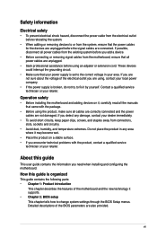
... Software support 1-27 1.11.1 Installing an operating system 1-27 1.11.2 Support DVD information 1-27 Chapter 2 BIOS information 2-1 2.1 Managing and updating your BIOS 2-1 2.1.1 ASUS Update utility 2-1 2.1.2 Creating a bootable floppy disk 2-2 2.1.3 ASUS EZ Flash 2 utility 2-3 2.1.4 AFUDOS utility 2-4 2.1.5 ASUS CrashFree BIOS 3 utility 2-5 2.2 BIOS setup program 2-7 2.2.1 BIOS menu screen 2-8 2.2.2 Menu bar 2-8 2.2.3 Navigation keys 2-8 2.2.4 Menu items 2-9 2.2.5 Sub-menu items 2-9 2.2.6 Configuration fields 2-9 2.2.7 Pop-up...
... Software support 1-27 1.11.1 Installing an operating system 1-27 1.11.2 Support DVD information 1-27 Chapter 2 BIOS information 2-1 2.1 Managing and updating your BIOS 2-1 2.1.1 ASUS Update utility 2-1 2.1.2 Creating a bootable floppy disk 2-2 2.1.3 ASUS EZ Flash 2 utility 2-3 2.1.4 AFUDOS utility 2-4 2.1.5 ASUS CrashFree BIOS 3 utility 2-5 2.2 BIOS setup program 2-7 2.2.1 BIOS menu screen 2-8 2.2.2 Menu bar 2-8 2.2.3 Navigation keys 2-8 2.2.4 Menu items 2-9 2.2.5 Sub-menu items 2-9 2.2.6 Configuration fields 2-9 2.2.7 Pop-up...
User Manual
Page 7
...the signal cables are connected. About this guide is broken, do not try to fix it supports. • Chapter 2: BIOS setup This chapter tells how to change system settings through the BIOS Setup menus. vii Operation safety • Before installing the motherboard and adding devices on a stable surface. • If...; If the power supply is organized This guide contains the following parts: • Chapter 1: Product introduction This chapter describes the features of the BIOS parameters are also provided. Detailed descriptions of the motherboard and the new technology it by yourself.
...the signal cables are connected. About this guide is broken, do not try to fix it supports. • Chapter 2: BIOS setup This chapter tells how to change system settings through the BIOS Setup menus. vii Operation safety • Before installing the motherboard and adding devices on a stable surface. • If...; If the power supply is organized This guide contains the following parts: • Chapter 1: Product introduction This chapter describes the features of the BIOS parameters are also provided. Detailed descriptions of the motherboard and the new technology it by yourself.
User Manual
Page 9
... actual running frequency is limited by the FSB. • Due to 600 MHz at 1MHz increment ASUS C.P.R. (CPU Parameter Recall) ASUS Special Features ASUS CrashFree BIOS 3 ASUS Q-Fan ASUS EZ Flash 2 ASUS MyLogo 2 AI NET 2 (continued on the next page) ix P5KPL SE specifications summary CPU. FSB tuning from 200 MHz up to the memory address limitation on 32...
... actual running frequency is limited by the FSB. • Due to 600 MHz at 1MHz increment ASUS C.P.R. (CPU Parameter Recall) ASUS Special Features ASUS CrashFree BIOS 3 ASUS Q-Fan ASUS EZ Flash 2 ASUS MyLogo 2 AI NET 2 (continued on the next page) ix P5KPL SE specifications summary CPU. FSB tuning from 200 MHz up to the memory address limitation on 32...
User Manual
Page 10
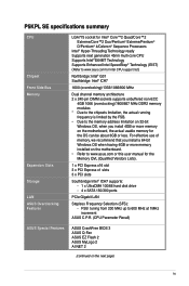
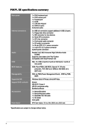
P5KPL SE specifications summary Rear panel Internal connectors Audio USB BIOS features Manageability Supported OS Support DVD contents Accessories Form factor 1 x PS/2 keyboard port 1 x PS/2 mouse port 1 x Parallel port 1 x COM 1 x LAN (RJ-45) port 4 x USB 2.0 ports 6-... H / W write protection, PnP, DMI v2.0, WfM2.0, SM BIOS v2.5, ACPI v2.0 WOL by PME (Power Management Event) , WOR by PME, WOR Windows 32-bit XP/Vista & 64-bit XP/Vista Drivers ASUS PC Probe II ASUS LiveUpdate utility Bundled software 1 x Serial ATA cables 1 x Serial ATA power cables 1 x UltraDMA 100 / 66 cable 1 x I/O shield ...
P5KPL SE specifications summary Rear panel Internal connectors Audio USB BIOS features Manageability Supported OS Support DVD contents Accessories Form factor 1 x PS/2 keyboard port 1 x PS/2 mouse port 1 x Parallel port 1 x COM 1 x LAN (RJ-45) port 4 x USB 2.0 ports 6-... H / W write protection, PnP, DMI v2.0, WfM2.0, SM BIOS v2.5, ACPI v2.0 WOL by PME (Power Management Event) , WOR by PME, WOR Windows 32-bit XP/Vista & 64-bit XP/Vista Drivers ASUS PC Probe II ASUS LiveUpdate utility Bundled software 1 x Serial ATA cables 1 x Serial ATA power cables 1 x UltraDMA 100 / 66 cable 1 x I/O shield ...
User Manual
Page 13
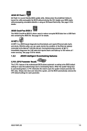
... RTC data. During the bootup process, AI NET 2 immediately diagnoses the LAN cable and reports shorts and faults up to overclocking failure, C.P.R. ASUS P5KPL SE 1-3 ASUS EZ Flash 2 EZ Flash 2 is a BIOS-based diagnostic tool that detects and reports Ethernet cable faults and shorts. Simply press the predefined hotkey to launch the utility and update...
... RTC data. During the bootup process, AI NET 2 immediately diagnoses the LAN cable and reports shorts and faults up to overclocking failure, C.P.R. ASUS P5KPL SE 1-3 ASUS EZ Flash 2 EZ Flash 2 is a BIOS-based diagnostic tool that detects and reports Ethernet cable faults and shorts. Simply press the predefined hotkey to launch the utility and update...
User Manual
Page 16
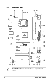
...) LAN1_USB12 Intel® ICS G31 B0 9LPRS954A3GLF 6 AUDIO EATXPWR PRI_IDE PCIEX1_1 1 PCIEX16 RTL 8111C P5KPL SE PCIEX1_2 7 PCIEX1_3 SPEAKER Intel® ICH7 PCI1 USB56 SATA1 SATA3 SATA2 SATA4 ALC662 CD AAFP SPDIF_OUT 15 14 13 PCI2 PCI3 8Mb BIOS Lithium Cell CMOS Power USB78 SB_PWR 8 CLRTC F_PANEL 12 11 10 9 Refer to 1.10...
...) LAN1_USB12 Intel® ICS G31 B0 9LPRS954A3GLF 6 AUDIO EATXPWR PRI_IDE PCIEX1_1 1 PCIEX16 RTL 8111C P5KPL SE PCIEX1_2 7 PCIEX1_3 SPEAKER Intel® ICH7 PCI1 USB56 SATA1 SATA3 SATA2 SATA4 ALC662 CD AAFP SPDIF_OUT 15 14 13 PCI2 PCI3 8Mb BIOS Lithium Cell CMOS Power USB78 SB_PWR 8 CLRTC F_PANEL 12 11 10 9 Refer to 1.10...

User Manual
Page 27
... that the cards do so may need IRQ assignments. Keep the screw for information on the system and change the necessary BIOS settings, if any. Turn on BIOS setup. 2. See Chapter 2 for later use . Ensure to the card. 3. Otherwise, conflicts will arise between the two...the software settings. 1. The following sub‑sections describe the slots and the expansion cards that came with the PCI Express specifications. ASUS P5KPL SE 1-17 1.8 Expansion slots In the future, you may cause you physical injury and damage motherboard components. 1.8.1 Installing an expansion card To...
... that the cards do so may need IRQ assignments. Keep the screw for information on the system and change the necessary BIOS settings, if any. Turn on BIOS setup. 2. See Chapter 2 for later use . Ensure to the card. 3. Otherwise, conflicts will arise between the two...the software settings. 1. The following sub‑sections describe the slots and the expansion cards that came with the PCI Express specifications. ASUS P5KPL SE 1-17 1.8 Expansion slots In the future, you may cause you physical injury and damage motherboard components. 1.8.1 Installing an expansion card To...
User Manual
Page 28
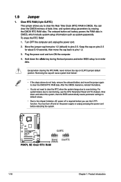
...RTC RAM, never remove the cap on CLRTC jumper default position. Shut down the key during the boot process and enter BIOS setup to overclocking, use the C.P.R. The onboard button cell battery powers the RAM data in CMOS. Turn OFF the ...BIOS automatically resets parameter settings to default values. • Due to the chipset limitation, AC power off and on pins 2-3 for about 5-10 seconds, then move the jumper again to pins 2-3. Clear RTC RAM (3-pin CLRTC) This jumper allows you use the CPU Parameter Recall (C.P.R.) feature. P5KPL SE CLRTC 12 23 Normal (Default) P5KPL SE...
...RTC RAM, never remove the cap on CLRTC jumper default position. Shut down the key during the boot process and enter BIOS setup to overclocking, use the C.P.R. The onboard button cell battery powers the RAM data in CMOS. Turn OFF the ...BIOS automatically resets parameter settings to default values. • Due to the chipset limitation, AC power off and on pins 2-3 for about 5-10 seconds, then move the jumper again to pins 2-3. Clear RTC RAM (3-pin CLRTC) This jumper allows you use the CPU Parameter Recall (C.P.R.) feature. P5KPL SE CLRTC 12 23 Normal (Default) P5KPL SE...
User Manual
Page 34
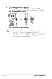
9. Front panel audio connector (10-1 pin AAFP) This connector is set the Front Panel Support Type item in the BIOS to avail of the front panel audio I /O module that you want to connect an AC97 front panel audio module to HD Audio. If ...'s high-definition audio capability. • By default, this connector is for details. 1-24 Chapter 1: Product introduction GND PRESENCE# SENSE1_RETUR SENSE2_RETUR AGND NC NC NC P5KPL SE AAFP PIN 1 PIN 1 MIC2 MICPWR Line out_R NC Line out_L PORT1 L PORT1 R PORT2 R SENSE_SEND PORT1 L HD-audio-compliant Legacy AC'97 pin definition ...
9. Front panel audio connector (10-1 pin AAFP) This connector is set the Front Panel Support Type item in the BIOS to avail of the front panel audio I /O module that you want to connect an AC97 front panel audio module to HD Audio. If ...'s high-definition audio capability. • By default, this connector is for details. 1-24 Chapter 1: Product introduction GND PRESENCE# SENSE1_RETUR SENSE2_RETUR AGND NC NC NC P5KPL SE AAFP PIN 1 PIN 1 MIC2 MICPWR Line out_R NC Line out_L PORT1 L PORT1 R PORT2 R SENSE_SEND PORT1 L HD-audio-compliant Legacy AC'97 pin definition ...
User Manual
Page 36
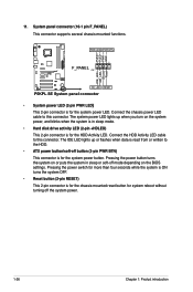
...LED (2-pin +HDLED) This 2-pin connector is for system reboot without turning off the system power. 1-26 Chapter 1: Product introduction Ground Reset HD_LED RESET P5KPL SE System panel connector • System power LED (2-pin PWR LED) This 2-pin connector is for the system power LED. The IDE LED lights up ...when you turn on the BIOS settings. Connect the HDD Activity LED cable to this connector. Pressing the power switch for more than four seconds while the system is ON turns...
...LED (2-pin +HDLED) This 2-pin connector is for system reboot without turning off the system power. 1-26 Chapter 1: Product introduction Ground Reset HD_LED RESET P5KPL SE System panel connector • System power LED (2-pin PWR LED) This 2-pin connector is for the system power LED. The IDE LED lights up ...when you turn on the BIOS settings. Connect the HDD Activity LED cable to this connector. Pressing the power switch for more than four seconds while the system is ON turns...

User Manual
Page 39
... of the original motherboard BIOS file to : • Save the current BIOS file • Download the latest BIOS file from the Internet • Update the BIOS from an updated BIOS file • Update the BIOS directly from the Internet, and • View the BIOS version information. Click the Utilities tab, then click Install ASUS Update. 3. ASUS P5KPL SE 2-1 This utility is...
... of the original motherboard BIOS file to : • Save the current BIOS file • Download the latest BIOS file from the Internet • Update the BIOS from an updated BIOS file • Update the BIOS directly from the Internet, and • View the BIOS version information. Click the Utilities tab, then click Install ASUS Update. 3. ASUS P5KPL SE 2-1 This utility is...
User Manual
Page 40
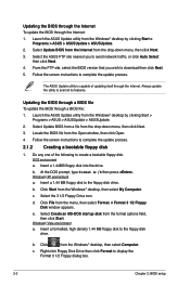
... utility to the floppy disk drive. Updating the BIOS through a BIOS file To update the BIOS through the Internet. Insert a 1.44 MB floppy disk to avail all its features. c. Launch the ASUS Update utility from the Windows® desktop by clicking Start > Programs > ASUS > ASUSUpdate > ASUSUpdate. 2. The ASUS Update utility is capable of the following to...
... utility to the floppy disk drive. Updating the BIOS through a BIOS file To update the BIOS through the Internet. Insert a 1.44 MB floppy disk to avail all its features. c. Launch the ASUS Update utility from the Windows® desktop by clicking Start > Programs > ASUS > ASUSUpdate > ASUSUpdate. 2. The ASUS Update utility is capable of the following to...

User Manual
Page 41
...so it . Go to the Tools menu to select EZ Flash 2 and press to download the latest BIOS file for this motherboard. 2. Visit the ASUS website at www.asus.com to enable it is found . ASUS P5KPL SE 2-3 Press + during the PowerOn Self Tests (POST). Then press . 4. You can support devices such... as USB flash disk, or floppy disk with FAT 32/16 format and single partition only. • Do not shut down or reset the system while updating the BIOS to a ...
...so it . Go to the Tools menu to select EZ Flash 2 and press to download the latest BIOS file for this motherboard. 2. Visit the ASUS website at www.asus.com to enable it is found . ASUS P5KPL SE 2-3 Press + during the PowerOn Self Tests (POST). Then press . 4. You can support devices such... as USB flash disk, or floppy disk with FAT 32/16 format and single partition only. • Do not shut down or reset the system while updating the BIOS to a ...

User Manual
Page 42
... not shut down or reset the system while updating the BIOS to the floppy disk. 4. Visit the ASUS website (www.asus.com) and download the latest BIOS file for the extension name. Boot the system in DOS mode. 3. Copying the current BIOS To copy the current BIOS file using the AFUDOS utility: 1. Boot the system in...
... not shut down or reset the system while updating the BIOS to the floppy disk. 4. Visit the ASUS website (www.asus.com) and download the latest BIOS file for the extension name. Boot the system in DOS mode. 3. Copying the current BIOS To copy the current BIOS file using the AFUDOS utility: 1. Boot the system in...
User Manual
Page 43
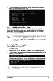
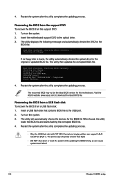
... BIOS 3 utility The ASUS CrashFree BIOS 3 is completed. Starting BIOS recovery... Starting BIOS recovery... Start flashing... Recovering the BIOS from a floppy disk To recover the BIOS from the hard disk drive. Bad BIOS checksum. Floppy found , the utility reads the BIOS file and starts flashing the corrupted BIOS file. DO NOT shut down or reset the system while updating the BIOS! ASUS P5KPL SE...
... BIOS 3 utility The ASUS CrashFree BIOS 3 is completed. Starting BIOS recovery... Starting BIOS recovery... Start flashing... Recovering the BIOS from a floppy disk To recover the BIOS from the hard disk drive. Bad BIOS checksum. Floppy found , the utility reads the BIOS file and starts flashing the corrupted BIOS file. DO NOT shut down or reset the system while updating the BIOS! ASUS P5KPL SE...
User Manual
Page 44
.... 4. Turn on the system. 2. Checking for floppy... Start flashing... 4. Visit the ASUS website (www.asus.com) to download the latest BIOS file. The utility then updates the corrupted BIOS file. Recovering the BIOS from a USB flash disk To recover the BIOS from the support DVD: 1. Doing so can support ASUS CrashFree BIOS 3. Turn on the system. 3. Completed. 4. Bad...
.... 4. Turn on the system. 2. Checking for floppy... Start flashing... 4. Visit the ASUS website (www.asus.com) to download the latest BIOS file. The utility then updates the corrupted BIOS file. Recovering the BIOS from a USB flash disk To recover the BIOS from the support DVD: 1. Doing so can support ASUS CrashFree BIOS 3. Turn on the system. 3. Completed. 4. Bad...


