User Manual
Page 8
... change system settings through the BIOS Setup menus. Optional documentation Your product package may include optional documentation, such as warranty flyers, that you need when installing and configuring the motherboard. Where to find more information Refer to perform when installing system components. ASUS websites The ASUS website provides updated information on the motherboard. • Chapter 2: BIOS setup...
... change system settings through the BIOS Setup menus. Optional documentation Your product package may include optional documentation, such as warranty flyers, that you need when installing and configuring the motherboard. Where to find more information Refer to perform when installing system components. ASUS websites The ASUS website provides updated information on the motherboard. • Chapter 2: BIOS setup...
User Manual
Page 32
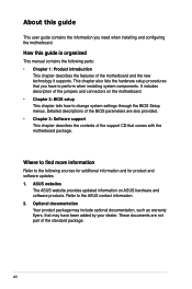
... the slot that they support. Make sure to use . 4. Remove the system unit cover (if your motherboard is completely seated on the system and change the necessary BIOS settings, if any. Assign an IRQ to install expansion cards. 1.8 Expansion slots In the future, you may cause... you physical injury and damage motherboard components. 1.8.1 Installing an expansion card To install an expansion card: 1. ...
... the slot that they support. Make sure to use . 4. Remove the system unit cover (if your motherboard is completely seated on the system and change the necessary BIOS settings, if any. Assign an IRQ to install expansion cards. 1.8 Expansion slots In the future, you may cause... you physical injury and damage motherboard components. 1.8.1 Installing an expansion card To install an expansion card: 1. ...

User Manual
Page 36
... requires an ATX power supply that can supply at least 500 mA on the keyboard (the default is the Space Bar). P5GC-MX/1333 R PS2_USBPWR 12 23 +5V (Default) P5GC-MX/1333 USB Device Wake Up +5VSB The total current consumed must NOT exceed the power supply capability (+5VSB) whether under normal condition or in the BIOS. 2. Set this...
... requires an ATX power supply that can supply at least 500 mA on the keyboard (the default is the Space Bar). P5GC-MX/1333 R PS2_USBPWR 12 23 +5V (Default) P5GC-MX/1333 USB Device Wake Up +5VSB The total current consumed must NOT exceed the power supply capability (+5VSB) whether under normal condition or in the BIOS. 2. Set this...
User Manual
Page 44
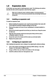
... pin definition pin definition AGND PRESENSE# MIC2_JD HP_HD AGND NC NC NC P5GC-MX/1333 R AAFP MIC2_L MIC2_R Line out_R NC Line out_L MIC2_L MIC2_R HP_R Jack_Sense HP_L P5GC-MX/1333 Front Panel Audio Connector • We recommend that supports either HD Audio...high-level signal to this connector is set the Front Panel Support Type item in the BIOS to [HD Audio]. P5GC-MX/1333 R CHASSIS GND Chassis Signal (Default) +5VSB_MB P5GC-MX/1333 Intrusion Connector 1-32 Chapter 1: Product introduction Connect one end of the motherboard's high-definition audio capability. •...
... pin definition pin definition AGND PRESENSE# MIC2_JD HP_HD AGND NC NC NC P5GC-MX/1333 R AAFP MIC2_L MIC2_R Line out_R NC Line out_L MIC2_L MIC2_R HP_R Jack_Sense HP_L P5GC-MX/1333 Front Panel Audio Connector • We recommend that supports either HD Audio...high-level signal to this connector is set the Front Panel Support Type item in the BIOS to [HD Audio]. P5GC-MX/1333 R CHASSIS GND Chassis Signal (Default) +5VSB_MB P5GC-MX/1333 Intrusion Connector 1-32 Chapter 1: Product introduction Connect one end of the motherboard's high-definition audio capability. •...
User Manual
Page 45
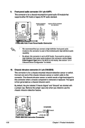
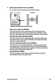
... LED PWR BTN HDLED RESET GND PWR PLEDPLED+ Reset Ground IDELEDIDELED+ P5GC-MX/1333 System Panel Connector • System power LED (2-pin PWRLED) This 2-pin connector is read from or written to this connector. The system power LED lights .... Connect the chassis power LED cable to this connector. The IDE LED lights up when you turn on the BIOS settings. ASUS P5GC-MX/1333 1-33 System panel connector (10-1 pin F_PANEL) This connector supports several chassis-mounted functions. Connect the HDD Activity LED cable to the HDD. • ATX power button/soft-off the system power.
... LED PWR BTN HDLED RESET GND PWR PLEDPLED+ Reset Ground IDELEDIDELED+ P5GC-MX/1333 System Panel Connector • System power LED (2-pin PWRLED) This 2-pin connector is read from or written to this connector. The system power LED lights .... Connect the chassis power LED cable to this connector. The IDE LED lights up when you turn on the BIOS settings. ASUS P5GC-MX/1333 1-33 System panel connector (10-1 pin F_PANEL) This connector supports several chassis-mounted functions. Connect the HDD Activity LED cable to the HDD. • ATX power button/soft-off the system power.

User Manual
Page 47
This chapter tells how to change the system settings through the BIOS Setup menus. Detailed descriptions of the BIOS parameters are also provided. 2 BIOS setup
This chapter tells how to change the system settings through the BIOS Setup menus. Detailed descriptions of the BIOS parameters are also provided. 2 BIOS setup
User Manual
Page 48
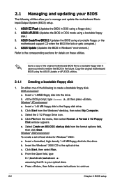
...set of the following utilities allow you need to the optical drive. From the Open field, type D:\bootdisk\makeboot a: assuming that D: is your BIOS The following to create a bootable floppy disk. Copy the original motherboard BIOS using a bootable floppy, or the motherboard support CD when the BIOS... menu, then select Format. ASUS CrashFree BIOS 2 (Updates the BIOS using the ASUS Update or AFUDOS utilities. 2.1.1 Creating a bootable floppy disk 1. b. Press , then follow screen instructions to manage and update the motherboard Basic Input/Output System (BIOS) setup. 1. At the ...
...set of the following utilities allow you need to the optical drive. From the Open field, type D:\bootdisk\makeboot a: assuming that D: is your BIOS The following to create a bootable floppy disk. Copy the original motherboard BIOS using a bootable floppy, or the motherboard support CD when the BIOS... menu, then select Format. ASUS CrashFree BIOS 2 (Updates the BIOS using the ASUS Update or AFUDOS utilities. 2.1.1 Creating a bootable floppy disk 1. b. Press , then follow screen instructions to manage and update the motherboard Basic Input/Output System (BIOS) setup. 1. At the ...
User Manual
Page 57
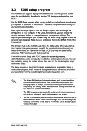
... according to the version of the firmware hub. ASUS P5GC-MX/1333 2-11 This section explains how to enter Setup after changing any BIOS settings, load the default settings to reconfigure your system using the navigation keys. • The default BIOS settings for this motherboard apply for most conditions to download the latest BIOS file for version information. This requires you...
... according to the version of the firmware hub. ASUS P5GC-MX/1333 2-11 This section explains how to enter Setup after changing any BIOS settings, load the default settings to reconfigure your system using the navigation keys. • The default BIOS settings for this motherboard apply for most conditions to download the latest BIOS file for version information. This requires you...

User Manual
Page 58
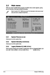
...IDE Slave IDE Configuration System Information Sub-menu items [19:34:30] [Wed 05/02/2007] [1.44M, 3.5 in the menu and change the settings. Some of a menu screen are the navigation keys for that particular menu. Use [+] or [-] to select a field. Navigation keys 2.2.2 Menu bar... the desired item is highlighted. 2.2.3 Navigation keys At the bottom right corner of the navigation keys differ from one screen to another. 2-12 Chapter 2: BIOS setup Use the navigation keys to select items in ] :[Not Detected] :[Not Detected] :[Not Detected] :[Not Detected] :[Not Detected] :[Not Detected]...
...IDE Slave IDE Configuration System Information Sub-menu items [19:34:30] [Wed 05/02/2007] [1.44M, 3.5 in the menu and change the settings. Some of a menu screen are the navigation keys for that particular menu. Use [+] or [-] to select a field. Navigation keys 2.2.2 Menu bar... the desired item is highlighted. 2.2.3 Navigation keys At the bottom right corner of the navigation keys differ from one screen to another. 2-12 Chapter 2: BIOS setup Use the navigation keys to select items in ] :[Not Detected] :[Not Detected] :[Not Detected] :[Not Detected] :[Not Detected] :[Not Detected]...
User Manual
Page 60
...] Use [ENTER], [TAB] or [SHIFT-TAB] to navigate through them. 2.3 Main menu When you enter the BIOS Setup program, the Main menu screen appears, giving you to set the system date. 2.3.3 Legacy Diskette A [1.44M, 3.5 in.] Sets the type of the basic system information. System Time System Date Legacy Diskette A Primary IDE Master Primary...
...] Use [ENTER], [TAB] or [SHIFT-TAB] to navigate through them. 2.3 Main menu When you enter the BIOS Setup program, the Main menu screen appears, giving you to set the system date. 2.3.3 Legacy Diskette A [1.44M, 3.5 in.] Sets the type of the basic system information. System Time System Date Legacy Diskette A Primary IDE Master Primary...
User Manual
Page 61
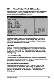
...BIOS automatically detects the values opposite the dimmed items (Device, Vendor, Size, LBA Mode, Block Mode, PIO Mode, Async DMA, Ultra DMA, and SMART monitoring). Setting to display the IDE device information. Configuration options: [Disabled] [Auto] Block (Multi-Sector Transfer) M [Auto] Enables or disables data multi-sectors transfers. Configuration options: [Disabled] [Auto] ASUS P5GC-MX/1333... 2-15 When set to Auto, the data transfer from and to the device occurs one sector...
...BIOS automatically detects the values opposite the dimmed items (Device, Vendor, Size, LBA Mode, Block Mode, PIO Mode, Async DMA, Ultra DMA, and SMART monitoring). Setting to display the IDE device information. Configuration options: [Disabled] [Auto] Block (Multi-Sector Transfer) M [Auto] Enables or disables data multi-sectors transfers. Configuration options: [Disabled] [Auto] ASUS P5GC-MX/1333... 2-15 When set to Auto, the data transfer from and to the device occurs one sector...

User Manual
Page 62
...Auto] [Disabled] [Enabled] 32Bit Data Transfer [Disabled] Enables or disables 32-bit data transfer. Set to Enhanced Mode if you to configure the item. Configuration options: [Disabled] [Enabled] 2.3.5 IDE...of the IDE operation mode depending on the operating system (OS) that you wish to set or change the configurations for the IDE devices installed in this menu allow you are using...OS, such as Windows® 2000/XP/Vista. Configuration options: [Auto] SMART Monitoring [Auto] Sets the Smart Monitoring, Analysis, and Reporting Technology. PIO Mode [Auto] Selects the PIO mode. Configuration options:...
...Auto] [Disabled] [Enabled] 32Bit Data Transfer [Disabled] Enables or disables 32-bit data transfer. Set to Enhanced Mode if you to configure the item. Configuration options: [Disabled] [Enabled] 2.3.5 IDE...of the IDE operation mode depending on the operating system (OS) that you wish to set or change the configurations for the IDE devices installed in this menu allow you are using...OS, such as Windows® 2000/XP/Vista. Configuration options: [Auto] SMART Monitoring [Auto] Sets the Smart Monitoring, Analysis, and Reporting Technology. PIO Mode [Auto] Selects the PIO mode. Configuration options:...
User Manual
Page 63
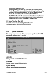
...[P-ATA] IDE Detect Time Out (Sec) [35] Selects the time out value for better OS compatibility. The BIOS automatically detects the items in this setting, you may use native OS on the Parallel ATA ports only if you did not install any of the general... AMI BIOS Displays the auto-detected BIOS information Processor Displays the auto-detected CPU specification System Memory Displays the auto-detected system memory ASUS P5GC-MX/1333 2-17 Configuration options: [0] [5] [10] [15] [20] [25] [30] [35] 2.3.6 System Information This menu gives you do not change the default setting for...
...[P-ATA] IDE Detect Time Out (Sec) [35] Selects the time out value for better OS compatibility. The BIOS automatically detects the items in this setting, you may use native OS on the Parallel ATA ports only if you did not install any of the general... AMI BIOS Displays the auto-detected BIOS information Processor Displays the auto-detected CPU specification System Memory Displays the auto-detected system memory ASUS P5GC-MX/1333 2-17 Configuration options: [0] [5] [10] [15] [20] [25] [30] [35] 2.3.6 System Information This menu gives you do not change the default setting for...
User Manual
Page 64
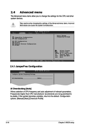
Take caution when changing the settings of relevant parameters. Configuration options: [Manual] [Auto] [Overclock Profile] 2-18 Chapter 2: BIOS setup If the system becomes unstable, return to malfunction. Frequencies higher than CPU manufacturer recommends are not guaranteed to Sub-screen F1 General Help F10 ... Overclocking [Auto] ConAffjriuegsqutureeSnycCsyPt/Uev.moltage Select Screen Select Item Enter Go to be stable. 2.4 Advanced menu The Advanced menu items allow you to change the settings for the CPU and other system devices.
Take caution when changing the settings of relevant parameters. Configuration options: [Manual] [Auto] [Overclock Profile] 2-18 Chapter 2: BIOS setup If the system becomes unstable, return to malfunction. Frequencies higher than CPU manufacturer recommends are not guaranteed to Sub-screen F1 General Help F10 ... Overclocking [Auto] ConAffjriuegsqutureeSnycCsyPt/Uev.moltage Select Screen Select Item Enter Go to be stable. 2.4 Advanced menu The Advanced menu items allow you to change the settings for the CPU and other system devices.
User Manual
Page 65
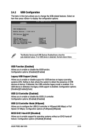
...device is detected, the legacy USB support is disabled. Configuration options: [Disabled] [Enabled] ASUS P5GC-MX/1333 2-19 Configuration options: [Disabled] [Enabled] Legacy USB Support [Auto] Allows you to ...Enabled] Legacy USB Support [Auto] USB 2.0 Controller [Enabled] USB 2.0 Controller Mode [HiSpeed] BIOS EHCI Hand-Off [Disabled] The Module Version and USB Devices Enabled items show the auto-detected ... mode is detected, the item shows None. Configuration options: [FullSpeed] [HiSpeed] BIOS EHCI Hand-Off [Disabled] Allows you to change the USB-related features. Select ...
...device is detected, the legacy USB support is disabled. Configuration options: [Disabled] [Enabled] ASUS P5GC-MX/1333 2-19 Configuration options: [Disabled] [Enabled] Legacy USB Support [Auto] Allows you to ...Enabled] Legacy USB Support [Auto] USB 2.0 Controller [Enabled] USB 2.0 Controller Mode [HiSpeed] BIOS EHCI Hand-Off [Disabled] The Module Version and USB Devices Enabled items show the auto-detected ... mode is detected, the item shows None. Configuration options: [FullSpeed] [HiSpeed] BIOS EHCI Hand-Off [Disabled] Allows you to change the USB-related features. Select ...
User Manual
Page 66
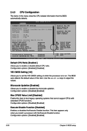
... adjust the values. This item appears only when you to set the VID CMOS setting at which the processor is to enable or disable the microcode updation. Configuration options: [Disabled] [Enabled] 2-20 Chapter 2: BIOS setup Disabled: The CPU Ratio would be user's manual.... Select Screen Select Item +- 2.4.3 CPU Configuration The items in this item. Configuration options: [Enabled] [Disabled] VID CMOS Setting [ 62] Allows you install a processor with extended ...
... adjust the values. This item appears only when you to set the VID CMOS setting at which the processor is to enable or disable the microcode updation. Configuration options: [Disabled] [Enabled] 2-20 Chapter 2: BIOS setup Disabled: The CPU Ratio would be user's manual.... Select Screen Select Item +- 2.4.3 CPU Configuration The items in this item. Configuration options: [Enabled] [Disabled] VID CMOS Setting [ 62] Allows you install a processor with extended ...
User Manual
Page 67
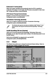
...ASUS P5GC-MX/1333 2-21 Change Option F1 General Help F10 Save and Exit ESC Exit Select Screen Select Item +- Configuration options: [Auto] [Disabled] Virtualization Technology [Enabled] Allows you to display the sub-menu. Configuration options: [Enabled] [Disabled] 2.4.4 Chipset The Chipset menu allows you to enable the C1E support. Set... Technology. Enhanced C1 Control [Auto] When set to [Enabled], you can adjust the system power settings in the operating system to use the EIST feature. When set to [Auto], the BIOS will automatically check the CPU's capability to ...
...ASUS P5GC-MX/1333 2-21 Change Option F1 General Help F10 Save and Exit ESC Exit Select Screen Select Item +- Configuration options: [Auto] [Disabled] Virtualization Technology [Enabled] Allows you to display the sub-menu. Configuration options: [Enabled] [Disabled] 2.4.4 Chipset The Chipset menu allows you to enable the C1E support. Set... Technology. Enhanced C1 Control [Auto] When set to [Enabled], you can adjust the system power settings in the operating system to use the EIST feature. When set to [Auto], the BIOS will automatically check the CPU's capability to ...

User Manual
Page 68
.... Configuration options: [2 Clocks] [3 Clocks] [4 Clocks] [5 Clocks] [6 Clocks] DRAM RAS# Activate to Precharge [15 Clocks] Sets the RAS Activate timing to the DDR SDRAM. Configure DRAM Timing by SPD [Enabled] When this item is enabled, the DRAM timing parameters ...the idle clocks after issuing a precharge command to Precharge timing. Configuration options: [Disabled] [Enabled, 1MB] [Enabled, 8MB] 2-22 Chapter 2: BIOS setup When disabled, you to enable DRAM Thermal Throttling to disabled for safe mode. Configuration options: [Internal VGA] [PCI Express/Int-VGA] [PCI...
.... Configuration options: [2 Clocks] [3 Clocks] [4 Clocks] [5 Clocks] [6 Clocks] DRAM RAS# Activate to Precharge [15 Clocks] Sets the RAS Activate timing to the DDR SDRAM. Configure DRAM Timing by SPD [Enabled] When this item is enabled, the DRAM timing parameters ...the idle clocks after issuing a precharge command to Precharge timing. Configuration options: [Disabled] [Enabled, 1MB] [Enabled, 8MB] 2-22 Chapter 2: BIOS setup When disabled, you to enable DRAM Thermal Throttling to disabled for safe mode. Configuration options: [Internal VGA] [PCI Express/Int-VGA] [PCI...
User Manual
Page 70
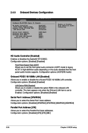
... on the audio standard that the front panel audio module supports. This item appears only when the Onboard LAN item is set the front panel audio connector (AAFP) mode to enable or disable the onboard PCIEX 10/100Mb LAN controller. Configuration options:.../IRQ4] [2E8/IRQ3] Parallel Port Address [378] Allows you to Enabled. Configuration options: [Disabled] [378] [278] [3BC] 2-24 Chapter 2: BIOS setup 2.4.5 Onboard Devices Configuration Configure Win627DHG Super IO Chipset HD Audio Controller [Enabled] Front Panel Support Type [HD Audio] Onboard PCIEX 10/100Mb LAN [Enabled...
... on the audio standard that the front panel audio module supports. This item appears only when the Onboard LAN item is set the front panel audio connector (AAFP) mode to enable or disable the onboard PCIEX 10/100Mb LAN controller. Configuration options:.../IRQ4] [2E8/IRQ3] Parallel Port Address [378] Allows you to Enabled. Configuration options: [Disabled] [378] [278] [3BC] 2-24 Chapter 2: BIOS setup 2.4.5 Onboard Devices Configuration Configure Win627DHG Super IO Chipset HD Audio Controller [Enabled] Front Panel Support Type [HD Audio] Onboard PCIEX 10/100Mb LAN [Enabled...

User Manual
Page 78
...When set to Enabled, the system waits for the NumLock. Configuration options: [Disabled] [Enabled] Set this item allows the BIOS to...2.6.2 Boot Settings Configuration Boot Settings Configuration Quick Boot [Enabled] Full Screen Logo [Enabled] AddOn ROM Display Mode [Force BIOS] Bootup Num...BIOS to boot the system. Configuration options: [Disabled] [Enabled] 2-32 Chapter 2: BIOS setup Add On ROM Display Mode [Force BIOS] Sets the display mode for PS/2 mouse. Configuration options: [Force BIOS...display feature. When set to [Disabled], BIOS performs all the POST items. Configuration options: ...
...When set to Enabled, the system waits for the NumLock. Configuration options: [Disabled] [Enabled] Set this item allows the BIOS to...2.6.2 Boot Settings Configuration Boot Settings Configuration Quick Boot [Enabled] Full Screen Logo [Enabled] AddOn ROM Display Mode [Force BIOS] Bootup Num...BIOS to boot the system. Configuration options: [Disabled] [Enabled] 2-32 Chapter 2: BIOS setup Add On ROM Display Mode [Force BIOS] Sets the display mode for PS/2 mouse. Configuration options: [Force BIOS...display feature. When set to [Disabled], BIOS performs all the POST items. Configuration options: ...


