
User Manual
Page 28
Hold down and reboot the system, then the BIOS automatically resets parameter settings to pins 1-2. 3. Except when clearing the RTC RAM, never remove the cap on pins 2-3 for about 5-10 seconds, then move the jumper again to clear the Real ... can clear the CMOS memory of date, time, and system setup parameters by erasing the CMOS RTC RAM data. P5G41T-M LX PLUS Clear RTC RAM To erase the RTC RAM: 1. Keep the cap on CLRTC jumper default position. The onboard button.... Shut down the key during the boot process and enter BIOS setup to pins 2-3. P5G41T-M LX PLUS 1.9 Jumpers 1.
Hold down and reboot the system, then the BIOS automatically resets parameter settings to pins 1-2. 3. Except when clearing the RTC RAM, never remove the cap on pins 2-3 for about 5-10 seconds, then move the jumper again to clear the Real ... can clear the CMOS memory of date, time, and system setup parameters by erasing the CMOS RTC RAM data. P5G41T-M LX PLUS Clear RTC RAM To erase the RTC RAM: 1. Keep the cap on CLRTC jumper default position. The onboard button.... Shut down the key during the boot process and enter BIOS setup to pins 2-3. P5G41T-M LX PLUS 1.9 Jumpers 1.
User Manual
Page 29
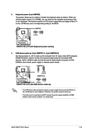
... to pins 2-3 (+5VSB), you to wake up feature. Set to +5VSB to enable or disable the keyboard wake-up from S1 sleep mode (CPU stopped, DRAM refreshed, system running in the BIOS. P5G41T-M LX PLUS ASUS P5G41T-M LX Series 1-19 This feature requires an ATX power supply that can supply at least 1A on the keyboard. P5G41T-M LX PLUS Keyboard power setting 3. P5G41T-M LX PLUS...
... to pins 2-3 (+5VSB), you to wake up feature. Set to +5VSB to enable or disable the keyboard wake-up from S1 sleep mode (CPU stopped, DRAM refreshed, system running in the BIOS. P5G41T-M LX PLUS ASUS P5G41T-M LX Series 1-19 This feature requires an ATX power supply that can supply at least 1A on the keyboard. P5G41T-M LX PLUS Keyboard power setting 3. P5G41T-M LX PLUS...
User Manual
Page 31
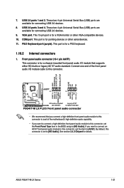
... connector is for pointing devices or other VGA-compatible devices. 10. PS/2 Keyboard port (purple). P5G41T-M LX PLUS ASUS P5G41T-M LX Series 1-21 This port is for connecting USB 2.0 devices. 9. By default, this connector, set to [AC97]. USB 2.0 ports 1 and 2. These two 4-pin Universal Serial Bus (USB) ports are available for details. If you want to connect an...
... connector is for pointing devices or other VGA-compatible devices. 10. PS/2 Keyboard port (purple). P5G41T-M LX PLUS ASUS P5G41T-M LX Series 1-21 This port is for connecting USB 2.0 devices. 9. By default, this connector, set to [AC97]. USB 2.0 ports 1 and 2. These two 4-pin Universal Serial Bus (USB) ports are available for details. If you want to connect an...

User Manual
Page 32
... connector Black Black Gray Black or gray • Pin 20 on the IDE connector is set as "Cable-Select," ensure that all other device jumpers have the same setting. 1-22 Chapter 1: Product introduction P5G41T-M LX PLUS P5G41T-M LX PLUS IDE connector If any device jumper is removed to... configure your device. Single device Two devices Drive jumper setting Cable-Select or Master Cable-Select Master Slave ...
... connector Black Black Gray Black or gray • Pin 20 on the IDE connector is set as "Cable-Select," ensure that all other device jumpers have the same setting. 1-22 Chapter 1: Product introduction P5G41T-M LX PLUS P5G41T-M LX PLUS IDE connector If any device jumper is removed to... configure your device. Single device Two devices Drive jumper setting Cable-Select or Master Cable-Select Master Slave ...


