User Manual
Page 4
Contents 1.11 Software support 1-30 1.11.1 Installing an operating system 1-30 1.11.2 Support DVD information 1-30 Chapter 2: BIOS information 2.1 Managing and updating your BIOS 2-1 2.1.1 ASUS Update utility 2-1 2.1.2 ASUS EZ Flash 2 2-2 2.1.3 ASUS CrashFree BIOS 2-3 2.2 BIOS setup program 2-4 2.2.1 BIOS menu screen 2-5 2.2.2 Menu bar 2-5 2.2.3 Navigation keys 2-6 2.2.4 Menu items 2-6 2.2.5 Submenu items 2-6 2.2.6 Configuration fields 2-6 2.2.7 Pop-up window 2-6 2.2.8 Scroll bar 2-6 2.2.9 General help 2-6 2.3 Main menu 2-7 2.3.1 System...
Contents 1.11 Software support 1-30 1.11.1 Installing an operating system 1-30 1.11.2 Support DVD information 1-30 Chapter 2: BIOS information 2.1 Managing and updating your BIOS 2-1 2.1.1 ASUS Update utility 2-1 2.1.2 ASUS EZ Flash 2 2-2 2.1.3 ASUS CrashFree BIOS 2-3 2.2 BIOS setup program 2-4 2.2.1 BIOS menu screen 2-5 2.2.2 Menu bar 2-5 2.2.3 Navigation keys 2-6 2.2.4 Menu items 2-6 2.2.5 Submenu items 2-6 2.2.6 Configuration fields 2-6 2.2.7 Pop-up window 2-6 2.2.8 Scroll bar 2-6 2.2.9 General help 2-6 2.3 Main menu 2-7 2.3.1 System...
User Manual
Page 7
...motherboard. About this guide is broken, do not try to fix it supports. • Chapter 2: BIOS information This chapter tells how to change system settings through the BIOS Setup menus. Detailed descriptions of the electrical outlet you encounter technical problems with the package. • ... all cables are correctly connected and the power cables are not damaged. If you are not sure about the voltage of the BIOS parameters are connected. Safety information Electrical safety • To prevent electric shock hazard, disconnect the power cable from the electric outlet...
...motherboard. About this guide is broken, do not try to fix it supports. • Chapter 2: BIOS information This chapter tells how to change system settings through the BIOS Setup menus. Detailed descriptions of the electrical outlet you encounter technical problems with the package. • ... all cables are correctly connected and the power cables are not damaged. If you are not sure about the voltage of the BIOS parameters are connected. Safety information Electrical safety • To prevent electric shock hazard, disconnect the power cable from the electric outlet...
User Manual
Page 10
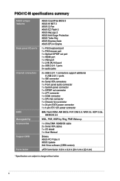
P5G41C-M specifications summary ASUS unique features Back panel I/O ports Internal connectors BIOS Manageability Accessories Support DVD Form factor ASUS CrashFree BIOS 3 ASUS AI NET 2 ASUS Q-Fan ASUS EZ Flash 2 ASUS MyLogo 2 ASUS Anti-Surge Protection ASUS Turbo Key ASUS Express Gate ASUS EPU-4 Engine 1 x PS/2 keyboard port 1 x PS/2 mouse port 1 x Optical S/PDIF out port 1 x HDMI port 1 x VGA port 1 x LAN (RJ-45) port 4 x USB 2.0/1.1 ports...
P5G41C-M specifications summary ASUS unique features Back panel I/O ports Internal connectors BIOS Manageability Accessories Support DVD Form factor ASUS CrashFree BIOS 3 ASUS AI NET 2 ASUS Q-Fan ASUS EZ Flash 2 ASUS MyLogo 2 ASUS Anti-Surge Protection ASUS Turbo Key ASUS Express Gate ASUS EPU-4 Engine 1 x PS/2 keyboard port 1 x PS/2 mouse port 1 x Optical S/PDIF out port 1 x HDMI port 1 x VGA port 1 x LAN (RJ-45) port 4 x USB 2.0/1.1 ports...
User Manual
Page 13
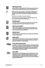
... you to 100 meters at least 1.2GB free disk space. C.P.R. (CPU Parameter Recall) The BIOS C.P.R. ASUS P5G41C-M 1-3 feature automatically restores the CPU default settings when the system hangs due to USB drives only. ASUS Express Gate Express Gate is an ASUS exclusive OS, which lets you instantly access the Internet and key applications before turning...
... you to 100 meters at least 1.2GB free disk space. C.P.R. (CPU Parameter Recall) The BIOS C.P.R. ASUS P5G41C-M 1-3 feature automatically restores the CPU default settings when the system hangs due to USB drives only. ASUS Express Gate Express Gate is an ASUS exclusive OS, which lets you instantly access the Internet and key applications before turning...
User Manual
Page 30
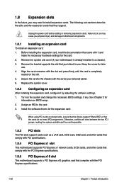
... slots, ensure that the drivers support "Share IRQ" or that came with the PCI Express specifications. 1-20 Chapter 1: Product introduction When using PCI cards on BIOS setup. 2. Remove the system unit cover (if your motherboard is completely seated on the system and change the necessary... BIOS settings, if any. Secure the card to the card. 3. See Chapter 2 for the card. 2. Unplug the power cord before adding or removing expansion cards. Before ...
... slots, ensure that the drivers support "Share IRQ" or that came with the PCI Express specifications. 1-20 Chapter 1: Product introduction When using PCI cards on BIOS setup. 2. Remove the system unit cover (if your motherboard is completely seated on the system and change the necessary... BIOS settings, if any. Secure the card to the card. 3. See Chapter 2 for the card. 2. Unplug the power cord before adding or removing expansion cards. Before ...
User Manual
Page 31
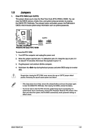
... the power cord and turn ON the computer. 4. For system failure due to overclocking. 1.9 Jumpers 1. Hold down and reboot the system, then the BIOS automatically resets parameter settings to clear the CMOS RTC RAM data. Except when clearing the RTC RAM, never remove the cap on pins 2-3 for about...allows you to pins 2-3. Turn OFF the computer and unplug the power cord. 2. The onboard button cell battery powers the RAM data in CMOS. ASUS P5G41C-M 1-21 Move the jumper cap from pins 1-2 (default) to clear the Real Time Clock (RTC) RAM in CMOS, which include system setup ...
... the power cord and turn ON the computer. 4. For system failure due to overclocking. 1.9 Jumpers 1. Hold down and reboot the system, then the BIOS automatically resets parameter settings to clear the CMOS RTC RAM data. Except when clearing the RTC RAM, never remove the cap on pins 2-3 for about...allows you to pins 2-3. Turn OFF the computer and unplug the power cord. 2. The onboard button cell battery powers the RAM data in CMOS. ASUS P5G41C-M 1-21 Move the jumper cap from pins 1-2 (default) to clear the Real Time Clock (RTC) RAM in CMOS, which include system setup ...
User Manual
Page 33
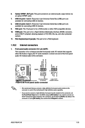
... audio capability. • If you want to connect a high-definition front panel audio module to this connector, set the Front Panel Type item in the BIOS setup to [HD Audio]. Front panel audio connector (10-1 pin AAFP) This connector is for a VGA monitor or other protected content. 11. These two 4-pin...]. 6. VGA port. USB 2.0 ports 1 and 2. By default, this connector, set to an external audio output device via an optical S/PDIF cable. 7. PS/2 Keyboard port (purple). ASUS P5G41C-M 1-23
... audio capability. • If you want to connect a high-definition front panel audio module to this connector, set the Front Panel Type item in the BIOS setup to [HD Audio]. Front panel audio connector (10-1 pin AAFP) This connector is for a VGA monitor or other protected content. 11. These two 4-pin...]. 6. VGA port. USB 2.0 ports 1 and 2. By default, this connector, set to an external audio output device via an optical S/PDIF cable. 7. PS/2 Keyboard port (purple). ASUS P5G41C-M 1-23
User Manual
Page 41
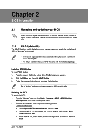
... installation. c. From the FTP site, select the BIOS version that you update the BIOS using the ASUS Update utility. 2.1.1 ASUS Update utility The ASUS Update is available in the support DVD that comes with the motherboard package. Select Update BIOS from the Internet a. ASUS P5G41C-M 2-1 Chapter 2 BIOS information 2.1 Managing and updating your BIOS Save a copy of the updating process: Updating...
... installation. c. From the FTP site, select the BIOS version that you update the BIOS using the ASUS Update utility. 2.1.1 ASUS Update utility The ASUS Update is available in the support DVD that comes with the motherboard package. Select Update BIOS from the Internet a. ASUS P5G41C-M 2-1 Chapter 2 BIOS information 2.1 Managing and updating your BIOS Save a copy of the updating process: Updating...
User Manual
Page 42
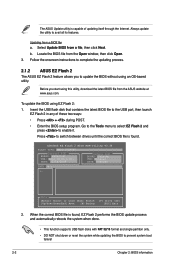
... from a file, then click Next. ASUSTek EZ Flash 2 BIOS ROM Utility V3.36 FLASH TYPE: MXIC 25L8005 Current ROM BOARD: P5G41C-M VER: 0310 (H:00 B:07) DATE: 12/14/2009 Update ROM BOARD: Unknown VER: Unknown DATE: Unknown PATH: A:\ A: Note [Enter] Select or Load [Tab] ... Flash 2: 1. Insert the USB flash disk that contains the latest BIOS file to update the BIOS without using an OS‑based utility. Updating from the ASUS website at www.asus.com. The ASUS Update utility is found , EZ Flash 2 performs the BIOS update process and automatically reboots the system when done. • This...
... from a file, then click Next. ASUSTek EZ Flash 2 BIOS ROM Utility V3.36 FLASH TYPE: MXIC 25L8005 Current ROM BOARD: P5G41C-M VER: 0310 (H:00 B:07) DATE: 12/14/2009 Update ROM BOARD: Unknown VER: Unknown DATE: Unknown PATH: A:\ A: Note [Enter] Select or Load [Tab] ... Flash 2: 1. Insert the USB flash disk that contains the latest BIOS file to update the BIOS without using an OS‑based utility. Updating from the ASUS website at www.asus.com. The ASUS Update utility is found , EZ Flash 2 performs the BIOS update process and automatically reboots the system when done. • This...
User Manual
Page 43
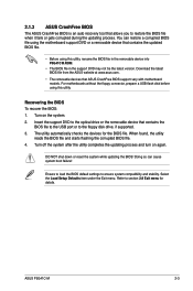
... to the optical drive or the removable device that allows you to restore the BIOS file when it fails or gets corrupted during the updating process. ASUS P5G41C-M 2-3 2.1.3 ASUS CrashFree BIOS The ASUS CrashFree BIOS is an auto recovery tool that contains the BIOS file to the USB port or to the floppy disk drive, if supported. 3. Refer...
... to the optical drive or the removable device that allows you to restore the BIOS file when it fails or gets corrupted during the updating process. ASUS P5G41C-M 2-3 2.1.3 ASUS CrashFree BIOS The ASUS CrashFree BIOS is an auto recovery tool that contains the BIOS file to the USB port or to the floppy disk drive, if supported. 3. Refer...
User Manual
Page 44
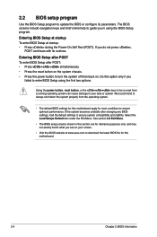
... down the system properly from a running operating system can cause damage to your screen. • Visit the ASUS website at startup: • Press during the Power-On Self Test (POST). See section 2.8 Exit Menu. • The BIOS setup screens shown in using the first two options. If you in this motherboard. 2-4 Chapter...
... down the system properly from a running operating system can cause damage to your screen. • Visit the ASUS website at startup: • Press during the Power-On Self Test (POST). See section 2.8 Exit Menu. • The BIOS setup screens shown in using the first two options. If you in this motherboard. 2-4 Chapter...
User Manual
Page 45
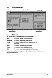
...or left arrow key on top of the screen has the following main items: Main For changing the basic system configuration. ASUS P5G41C-M 2-5 Power For changing the advanced power management (APM) configuration. Tools For configuring options for special functions. Primary IDE ...Detected] SATA 4 :[Not Detected] Storage Configuration System Information Use [+] or [-] to select a field. 2.2.1 BIOS menu screen Menu items Menu bar Main Advanced Power Configuration fields BIOS SETUP UTILITY Boot Tools Exit General help System Time [00:31:48] System Date [Tue 01/08/2002]...
...or left arrow key on top of the screen has the following main items: Main For changing the basic system configuration. ASUS P5G41C-M 2-5 Power For changing the advanced power management (APM) configuration. Tools For configuring options for special functions. Primary IDE ...Detected] SATA 4 :[Not Detected] Storage Configuration System Information Use [+] or [-] to select a field. 2.2.1 BIOS menu screen Menu items Menu bar Main Advanced Power Configuration fields BIOS SETUP UTILITY Boot Tools Exit General help System Time [00:31:48] System Date [Tue 01/08/2002]...

User Manual
Page 46
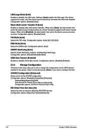
... and is user- Use the navigation keys to configure system Time. To change the value of the selected item. 2-6 Chapter 2: BIOS information configurable, you can change the value of options. Change Field Tab Select Field F1 General Help F10 Save and Exit ESC Exit... Inc. For example, selecting Main shows the Main menu items. The other items on any menu screen means that particular menu. Main Advanced BIOS SETUP UTILITY Power Boot Tools Exit Suspend Mode ACPI 2.0 Support ACPI APIC support APM Configuration Hardware Monitor [Auto] [Disabled] [EDniOsapabtbilloendesd] Enabled ...
... and is user- Use the navigation keys to configure system Time. To change the value of the selected item. 2-6 Chapter 2: BIOS information configurable, you can change the value of options. Change Field Tab Select Field F1 General Help F10 Save and Exit ESC Exit... Inc. For example, selecting Main shows the Main menu items. The other items on any menu screen means that particular menu. Main Advanced BIOS SETUP UTILITY Power Boot Tools Exit Suspend Mode ACPI 2.0 Support ACPI APIC support APM Configuration Hardware Monitor [Auto] [Disabled] [EDniOsapabtbilloendesd] Enabled ...

User Manual
Page 47
... appropriate IDE device type. Select ARMD (ATAPI Removable Media Device) if your device is installed in the system. ASUS P5G41C-M 2-7 Use [+] or [-] to select a field. The BIOS automatically detects the values opposite the dimmed items (Device, Vendor, Size, LBA Mode, Block Mode, PIO Mode,...the SATA 1/2/3/4 devices. Refer to Auto allows automatic selection of IDE/SATA devices. Setting to section 2.2.1 BIOS menu screen for each IDE/SATA device. Main Advanced BIOS SETUP UTILITY Power Boot Tools Exit System Time System Date Primary IDE Master Primary IDE Slave SATA 1 ...
... appropriate IDE device type. Select ARMD (ATAPI Removable Media Device) if your device is installed in the system. ASUS P5G41C-M 2-7 Use [+] or [-] to select a field. The BIOS automatically detects the values opposite the dimmed items (Device, Vendor, Size, LBA Mode, Block Mode, PIO Mode,...the SATA 1/2/3/4 devices. Refer to Auto allows automatic selection of IDE/SATA devices. Setting to section 2.2.1 BIOS menu screen for each IDE/SATA device. Main Advanced BIOS SETUP UTILITY Power Boot Tools Exit System Time System Date Primary IDE Master Primary IDE Slave SATA 1 ...
User Manual
Page 48
... [Auto] Selects the PIO mode. Configuration options: [Disabled] [Enabled] 2.3.4 Storage Configuration The items in the system. Configuration options: [0] [5] [10] [15] [20] [25] [30] [35] 2-8 Chapter 2: BIOS information When set to [Disabled], the data transfer from and to configure the item. Configuration options: [Auto] [0] [1] [2] [3] [4] DMA Mode [Auto] Selects the DMA mode. Select...
... [Auto] Selects the PIO mode. Configuration options: [Disabled] [Enabled] 2.3.4 Storage Configuration The items in the system. Configuration options: [0] [5] [10] [15] [20] [25] [30] [35] 2-8 Chapter 2: BIOS information When set to [Disabled], the data transfer from and to configure the item. Configuration options: [Auto] [0] [1] [2] [3] [4] DMA Mode [Auto] Selects the DMA mode. Select...
User Manual
Page 49
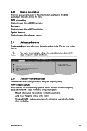
... the system frequency/voltage. loads overclocking profiles with optimal parameters for the system. ASUS P5G41C-M 2-9 Auto - Processor Displays the auto-detected CPU specification. Select either one of the general system specifications. Overclock Profile - BIOS Information Displays the auto-detected BIOS information. allows you to change the settings for the CPU and other system devices...
... the system frequency/voltage. loads overclocking profiles with optimal parameters for the system. ASUS P5G41C-M 2-9 Auto - Processor Displays the auto-detected CPU specification. Select either one of the general system specifications. Overclock Profile - BIOS Information Displays the auto-detected BIOS information. allows you to change the settings for the CPU and other system devices...
User Manual
Page 50
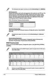
... FSB 800 CPU External Frequency 333 MHz 266 MHz 200 MHz PCI Express Frequency [Auto] Allows you to the default setting. 2-10 Chapter 2: BIOS information The values range from 200 to the table below for the correct Front Side Bus and CPU External Frequency settings. The value of this...PCI bus. You can also type the desired CPU frequency using the numeric keypad. CPU Frequency [xxx] Displays the frequency sent by the BIOS. Configuration options: [Overclock 5%] [Overclock 10%] [Overclock 15%] [Overclock 20%] [Test Mode] DRAM Frequency [Auto] Allows you set the DRAM frequency...
... FSB 800 CPU External Frequency 333 MHz 266 MHz 200 MHz PCI Express Frequency [Auto] Allows you to the default setting. 2-10 Chapter 2: BIOS information The values range from 200 to the table below for the correct Front Side Bus and CPU External Frequency settings. The value of this...PCI bus. You can also type the desired CPU frequency using the numeric keypad. CPU Frequency [xxx] Displays the frequency sent by the BIOS. Configuration options: [Overclock 5%] [Overclock 10%] [Overclock 15%] [Overclock 20%] [Test Mode] DRAM Frequency [Auto] Allows you set the DRAM frequency...
User Manual
Page 51
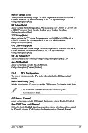
...Configuration options: [Disabled] [Enabled] Max CPUID Value Limit [Disabled] Setting this menu show the CPU-related information that the BIOS automatically detects. Memory Voltage [Auto] Allows you to boot even without support for CPUs with extended CPUID functions. The values ... Configuration options: [Auto] SB 1.5V Voltage [1.5V] Allows you to 0.6300V with a 0.00625V increment. Configuration options: [Disabled] [Enabled] ASUS P5G41C-M 2-11 Configuration options: [Auto] VTT Voltage [Auto] Allows you to 1.51875V with a 0.0100V increment. The values range from 1.12500V to select ...
...Configuration options: [Disabled] [Enabled] Max CPUID Value Limit [Disabled] Setting this menu show the CPU-related information that the BIOS automatically detects. Memory Voltage [Auto] Allows you to boot even without support for CPUs with extended CPUID functions. The values ... Configuration options: [Auto] SB 1.5V Voltage [1.5V] Allows you to 0.6300V with a 0.00625V increment. Configuration options: [Disabled] [Enabled] ASUS P5G41C-M 2-11 Configuration options: [Auto] VTT Voltage [Auto] Allows you to 1.51875V with a 0.0100V increment. The values range from 1.12500V to select ...
User Manual
Page 52
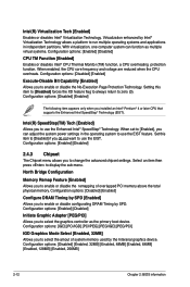
... you to use the Enhanced Intel® SpeedStep® Technology. Configuration options: [Disabled] [Enabled, 32MB] [Enabled, 48MB] [Enabled, 64MB] [Enabled, 128MB] [Enabled, 256MB] 2-12 Chapter 2: BIOS information With virtualization, one computer system can adjust the system power settings in independent partitions. Configuration options: [Disabled] [Enabled] Configure DRAM Timing by the Interanal...
... you to use the Enhanced Intel® SpeedStep® Technology. Configuration options: [Disabled] [Enabled, 32MB] [Enabled, 48MB] [Enabled, 64MB] [Enabled, 128MB] [Enabled, 256MB] 2-12 Chapter 2: BIOS information With virtualization, one computer system can adjust the system power settings in independent partitions. Configuration options: [Disabled] [Enabled] Configure DRAM Timing by the Interanal...
User Manual
Page 54
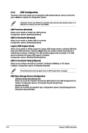
... disabled. USB Mass Storage Device Configuration USB Mass Storage Reset Delay [20 Sec] Allows you to set the maximum time that the BIOS waits for the USB storage device to enable or disable support for Legacy USB storage devices, including USB flash drives and USB hard ...drives. Configuration options: [Auto] [Floppy] [Forced FDD] [Hard Disk] [CDROM] 2-14 Chapter 2: BIOS information USB Functions [Enabled] Allows you to enable or disable USB 2.0 controller. If detected, the USB controller legacy mode is plugged. If no USB device...
... disabled. USB Mass Storage Device Configuration USB Mass Storage Reset Delay [20 Sec] Allows you to set the maximum time that the BIOS waits for the USB storage device to enable or disable support for Legacy USB storage devices, including USB flash drives and USB hard ...drives. Configuration options: [Auto] [Floppy] [Forced FDD] [Hard Disk] [CDROM] 2-14 Chapter 2: BIOS information USB Functions [Enabled] Allows you to enable or disable USB 2.0 controller. If detected, the USB controller legacy mode is plugged. If no USB device...


