
Motherboard Installation Guide
Page 30
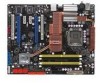
Coaxial S/PDIF Out port 3. Line Out port (lime) 6. Clear RTC RAM (Gaming Level Switch Design) Rear panel connectors 1. Line In port (light blue) 5. Center/Subwoofer port (orange) 8. USB 2.0 ports 1 and 2 11. USB 2.0 ports 5 and 6 Page 2-14 2-...
Coaxial S/PDIF Out port 3. Line Out port (lime) 6. Clear RTC RAM (Gaming Level Switch Design) Rear panel connectors 1. Line In port (light blue) 5. Center/Subwoofer port (orange) 8. USB 2.0 ports 1 and 2 11. USB 2.0 ports 5 and 6 Page 2-14 2-...
Motherboard Installation Guide
Page 48
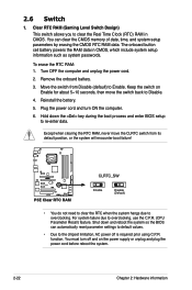
... down and reboot the system so the BIOS can clear the CMOS memory of date, time, and system setup parameters by erasing the CMOS RTC RAM data. Remove the onboard battery. 3. For system failure due to re-enter data. Shut down the key during the boot process and enter BIOS ... power cord and turn off is required prior using C.P.R. Move the switch from its default position, or the system will encounter boot failure! ® P5E P5E Clear RTC RAM CLRTC_SW Enable Disable (Default) • You do not need to clear the RTC when the system hangs due to the chipset limitation, AC power...
... down and reboot the system so the BIOS can clear the CMOS memory of date, time, and system setup parameters by erasing the CMOS RTC RAM data. Remove the onboard battery. 3. For system failure due to re-enter data. Shut down the key during the boot process and enter BIOS ... power cord and turn off is required prior using C.P.R. Move the switch from its default position, or the system will encounter boot failure! ® P5E P5E Clear RTC RAM CLRTC_SW Enable Disable (Default) • You do not need to clear the RTC when the system hangs due to the chipset limitation, AC power...

Motherboard Installation Guide
Page 75
...this motherboard apply for most conditions to ensure optimum performance. This requires you can change the power management settings. If you can enable the security password feature or change the configuration of the SPI chip. Select the Load Setup Defaults item under the Exit Menu. ASUS P5E ... Serial Peripheral Interface (SPI) chip that the computer can recognize these changes and record them in the CMOS RAM of your computer in this section are installing a motherboard, reconfiguring your system, or prompted to "Run Setup." Use the BIOS Setup program when you with its test...
...this motherboard apply for most conditions to ensure optimum performance. This requires you can change the power management settings. If you can enable the security password feature or change the configuration of the SPI chip. Select the Load Setup Defaults item under the Exit Menu. ASUS P5E ... Serial Peripheral Interface (SPI) chip that the computer can recognize these changes and record them in the CMOS RAM of your computer in this section are installing a motherboard, reconfiguring your system, or prompted to "Run Setup." Use the BIOS Setup program when you with its test...

Motherboard Installation Guide
Page 101
... press . 3. Select Screen Select Item Enter Change F1 General Help F10 Save and Exit ESC Exit v02.61 (C)Copyright 1985-2007, American Megatrends, Inc. ASUS P5E 4-35 Select an item then press to change the supervisor password, follow the same steps as in setting a user password. The message "Password Installed" appears...configuration options. After you set or change other items appear to allow you can clear it by erasing the CMOS Real Time Clock (RTC) RAM. Select the Change Supervisor Password item and press . 2. Confirm the password when prompted. again to disabled password.
... press . 3. Select Screen Select Item Enter Change F1 General Help F10 Save and Exit ESC Exit v02.61 (C)Copyright 1985-2007, American Megatrends, Inc. ASUS P5E 4-35 Select an item then press to change the supervisor password, follow the same steps as in setting a user password. The message "Password Installed" appears...configuration options. After you set or change other items appear to allow you can clear it by erasing the CMOS Real Time Clock (RTC) RAM. Select the Change Supervisor Password item and press . 2. Confirm the password when prompted. again to disabled password.
Motherboard Installation Guide
Page 106
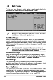
... Select Ok to save changes and exit. Select Ok to load default values. Pressing does not immediately exit this operation. Press to the non-volatile RAM. 4-40 Chapter 4: BIOS setup 4.9 Exit menu The Exit menu items allow you to load the optimal or failsafe default values for the BIOS items,...or make other than System Date, System Time, and Password, the BIOS asks for a confirmation before exiting. An onboard backup battery sustains the CMOS RAM so it stays on the Setup menus. If you attempt to exit the Setup program without saving your changes, the program prompts you with a ...
... Select Ok to save changes and exit. Select Ok to load default values. Pressing does not immediately exit this operation. Press to the non-volatile RAM. 4-40 Chapter 4: BIOS setup 4.9 Exit menu The Exit menu items allow you to load the optimal or failsafe default values for the BIOS items,...or make other than System Date, System Time, and Password, the BIOS asks for a confirmation before exiting. An onboard backup battery sustains the CMOS RAM so it stays on the Setup menus. If you attempt to exit the Setup program without saving your changes, the program prompts you with a ...

Motherboard Installation Guide
Page 174
Test special keyboard controller for Winbond 977 series Super I/O chips. Reset keyboard for Winbond 977 series Super I /O resource -Search for override. Test F000h segment shadow to SPURIOUS_soft_HDLR. Initial interrupts vector table. If CMOS checksum fails, use . ... CHIP INIT CLK CHECKCPU INTRINIT REC MPS Reserved Reserved SET FDD INITINT9 Description CPU Initiation Test CMOS R/W functionality. Early chipset initialization: -Disable shadow RAM -Disable L2 cache (socket 7 or below) -Program basic chipset registers Detect memory -Auto-detection of DRAM size, type and ECC. -Auto...
Test special keyboard controller for Winbond 977 series Super I/O chips. Reset keyboard for Winbond 977 series Super I /O resource -Search for override. Test F000h segment shadow to SPURIOUS_soft_HDLR. Initial interrupts vector table. If CMOS checksum fails, use . ... CHIP INIT CLK CHECKCPU INTRINIT REC MPS Reserved Reserved SET FDD INITINT9 Description CPU Initiation Test CMOS R/W functionality. Early chipset initialization: -Disable shadow RAM -Disable L2 cache (socket 7 or below) -Program basic chipset registers Detect memory -Auto-detection of DRAM size, type and ECC. -Auto...


