User Guide
Page 3
... Where to find more information viii Conventions used in this guide ix Typography ix P5CR-VM specifications summary x Chapter 1: Product introduction 1.1 Welcome 1-1 1.2 Package contents 1-1 1.3 Special features 1-2 1.3.1 Product highlights 1-2 1.3.2 Innovative ASUS features 1-4 Chapter 2: Hardware information 2.1 Before you proceed 2-1 2.2 Motherboard overview 2-2 2.2.1 Placement direction 2-2 2.2.2 Screw holes 2-2 2.2.3 Motherboard layout 2-3 2.2.4 Layout contents 2-4 2.3 Central Processing Unit (CPU 2-6 2.3.1 Installing the CPU...
... Where to find more information viii Conventions used in this guide ix Typography ix P5CR-VM specifications summary x Chapter 1: Product introduction 1.1 Welcome 1-1 1.2 Package contents 1-1 1.3 Special features 1-2 1.3.1 Product highlights 1-2 1.3.2 Innovative ASUS features 1-4 Chapter 2: Hardware information 2.1 Before you proceed 2-1 2.2 Motherboard overview 2-2 2.2.1 Placement direction 2-2 2.2.2 Screw holes 2-2 2.2.3 Motherboard layout 2-3 2.2.4 Layout contents 2-4 2.3 Central Processing Unit (CPU 2-6 2.3.1 Installing the CPU...
User Guide
Page 22
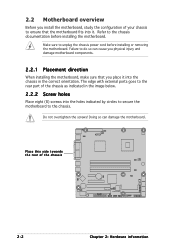
... Before you place it . The edge with external ports goes to the rear part of the chassis P5CR-VM 2-2 Chapter 2: Hardware information Doing so can cause you physical injury and damage motherboard components. 2.2.1 Placement direction When installing the motherboard, make sure that the motherboard fits into it into the holes indicated by circles...
... Before you place it . The edge with external ports goes to the rear part of the chassis P5CR-VM 2-2 Chapter 2: Hardware information Doing so can cause you physical injury and damage motherboard components. 2.2.1 Placement direction When installing the motherboard, make sure that the motherboard fits into it into the holes indicated by circles...
User Guide
Page 27
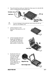
.... 3. Press the load lever with your thumb (A), then move it is on the bottom-left (B) until it to remove (B). Lift the load lever in the direction of the socket. Gold triangle mark ASUS P5CR-VM A 2-7
.... 3. Press the load lever with your thumb (A), then move it is on the bottom-left (B) until it to remove (B). Lift the load lever in the direction of the socket. Gold triangle mark ASUS P5CR-VM A 2-7

User Guide
Page 29
... the chassis before you use ASUS-certified multi-directional heatsink and fan. To install the CPU heatsink and fan: 1. 2.3.2 Installing the CPU heatsink and fan The Intel® Pentium® 4 LGA775 processor requires a specially designed heatsink and fan assembly to the CPU fan connector. Visit the ASUS website for (www.asus.com) for emphasis.) ASUS P5CR-VM 2-9
... the chassis before you use ASUS-certified multi-directional heatsink and fan. To install the CPU heatsink and fan: 1. 2.3.2 Installing the CPU heatsink and fan The Intel® Pentium® 4 LGA775 processor requires a specially designed heatsink and fan assembly to the CPU fan connector. Visit the ASUS website for (www.asus.com) for emphasis.) ASUS P5CR-VM 2-9

User Guide
Page 34
... before adding or removing DIMMs or other system components. Do not force a DIMM into the socket until the retaining clips snap back in only one direction. Firmly insert the DIMM into a socket to avoid damaging the DIMM. • The DDR2 DIMM sockets do so can cause severe damage to remove a DIMM...
... before adding or removing DIMMs or other system components. Do not force a DIMM into the socket until the retaining clips snap back in only one direction. Firmly insert the DIMM into a socket to avoid damaging the DIMM. • The DDR2 DIMM sockets do so can cause severe damage to remove a DIMM...

User Guide
Page 36
... assignments Standard interrupt assignments IRQ Priority 0 1 1 2 2 - 3 11 4 12 5 13 6 14 7 15 8 3 9 4 10 5 11 6 12 7 13 8 14 9 15 10 Standard Function System Timer Keyboard Controller Re-direct to IRQ #9 Communications Port (COM2)* Communications Port (COM1)* IRQ holder for PCI steering* Floppy Disk Controller Printer Port (LPT1)* System CMOS/Real Time Clock IRQ...
... assignments Standard interrupt assignments IRQ Priority 0 1 1 2 2 - 3 11 4 12 5 13 6 14 7 15 8 3 9 4 10 5 11 6 12 7 13 8 14 9 15 10 Standard Function System Timer Keyboard Controller Re-direct to IRQ #9 Communications Port (COM2)* Communications Port (COM1)* IRQ holder for PCI steering* Floppy Disk Controller Printer Port (LPT1)* System CMOS/Real Time Clock IRQ...

User Guide
Page 68
... I n s t a l l A S U S U p d a t e V X . The ASUS Update utility is copied to : • Save the current BIOS file • Download the latest BIOS file from the Internet • Update the BIOS from an updated BIOS file • Update the BIOS directly from the Internet, and • View the BIOS version... you to manage, save, and update the motherboard BIOS in the optical drive. 4.1.5 ASUS Update utility The ASUS Update is a utility that comes with the motherboard package. ASUS Update requires an Internet connection either through a network or an Internet Service Provider (ISP)....
... I n s t a l l A S U S U p d a t e V X . The ASUS Update utility is copied to : • Save the current BIOS file • Download the latest BIOS file from the Internet • Update the BIOS from an updated BIOS file • Update the BIOS directly from the Internet, and • View the BIOS version... you to manage, save, and update the motherboard BIOS in the optical drive. 4.1.5 ASUS Update utility The ASUS Update is a utility that comes with the motherboard package. ASUS Update requires an Internet connection either through a network or an Internet Service Provider (ISP)....

User Guide
Page 86
... disable the Azalia controller. Configuration options: [Disabled] [3F8/IRQ4] [3E8/IRQ4] [2E8/IRQ3] Serial Port2 Address [2F8/IRQ3] Allows you to E P P. Configuration options: [Normal] [Bi-directional] [EPP] [ECP] ECP Mode DMA Channel [DMA3] Appears only when the Parallel Port Mode is set to select the Parallel Port base addresses.
... disable the Azalia controller. Configuration options: [Disabled] [3F8/IRQ4] [3E8/IRQ4] [2E8/IRQ3] Serial Port2 Address [2F8/IRQ3] Allows you to E P P. Configuration options: [Normal] [Bi-directional] [EPP] [ECP] ECP Mode DMA Channel [DMA3] Appears only when the Parallel Port Mode is set to select the Parallel Port base addresses.