
User Guide
Page 5
... 5.4.2 Windows® 2003 Server 5-20 5.4.3 Red Hat® Linux 9.0 5-21 Appendix: Reference information A.1 P5CR-L(S) block diagram A-1 v Contents 4.5 Power menu 4-29 4.5.1 ACPI APIC Support 4-29 4.5.2 APM Configuration 4-30 4.5.3 Hardware Monitor 4-31 4.6 Boot menu 4-33 4.6.1 Boot Device Priority 4-33 4.6.2 Boot Settings Configuration 4-34 4.6.3 Security 4-35 4.7 Exit menu 4-37 Chapter 5: RAID configuration and driver installation 5.1 RAID configurations 5-1 5.1.1 RAID definitions 5-1 5.1.2 Installing hard disk drives 5-2 5.1.3 Setting the RAID item in BIOS 5-2 5.1.4 Using...
... 5.4.2 Windows® 2003 Server 5-20 5.4.3 Red Hat® Linux 9.0 5-21 Appendix: Reference information A.1 P5CR-L(S) block diagram A-1 v Contents 4.5 Power menu 4-29 4.5.1 ACPI APIC Support 4-29 4.5.2 APM Configuration 4-30 4.5.3 Hardware Monitor 4-31 4.6 Boot menu 4-33 4.6.1 Boot Device Priority 4-33 4.6.2 Boot Settings Configuration 4-34 4.6.3 Security 4-35 4.7 Exit menu 4-37 Chapter 5: RAID configuration and driver installation 5.1 RAID configurations 5-1 5.1.1 RAID definitions 5-1 5.1.2 Installing hard disk drives 5-2 5.1.3 Setting the RAID item in BIOS 5-2 5.1.4 Using...
User Guide
Page 8
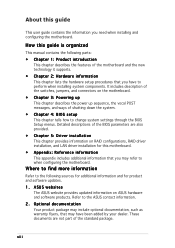
... the switches, jumpers, and connectors on the motherboard. • Chapter 3: Powering up This chapter describes the power up sequence, the vocal POST messages, and ways of the motherboard and the new technology it supports. • Chapter 2: Hardware information This chapter lists the hardware setup procedures that you have been added by your dealer. ASUS websites The ASUS website provides updated information on RAID configurations, RAID driver installation, and LAN driver installation for product and software updates. 1. Optional documentation...
... the switches, jumpers, and connectors on the motherboard. • Chapter 3: Powering up This chapter describes the power up sequence, the vocal POST messages, and ways of the motherboard and the new technology it supports. • Chapter 2: Hardware information This chapter lists the hardware setup procedures that you have been added by your dealer. ASUS websites The ASUS website provides updated information on RAID configurations, RAID driver installation, and LAN driver installation for product and software updates. 1. Optional documentation...
User Guide
Page 10
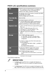
... up to 4 GB of system memory 1 x PCI-X® 133 MHz*/64-bit slot (optional ZCR support, PCI-X 1.0) 1 x PCI-X® 133 MHz/64-bit slot (PCI-X 1.0) 1 x PCI Express™ x1 slot (PCI Express™ 1.0a) 2 x PCI 33 MHz/32-bit/5V (PCI 2.3) 1 x MINI PCI® socket for the ASUS Server Management Board Intel® ICH6R Southbridge supports: - 2 x Ultra DMA 100/66/33 hard disk drives - 4 x Serial ATA hard disks with RAID 0, RAID 1 configuration *For P5CR-LS, Adaptec AIC-7901 PCI-X U320 SCSI controller supports: - 1 x SCSI U320 with RAID 0, RAID 1, and RAID 0+1 configuration -
... up to 4 GB of system memory 1 x PCI-X® 133 MHz*/64-bit slot (optional ZCR support, PCI-X 1.0) 1 x PCI-X® 133 MHz/64-bit slot (PCI-X 1.0) 1 x PCI Express™ x1 slot (PCI Express™ 1.0a) 2 x PCI 33 MHz/32-bit/5V (PCI 2.3) 1 x MINI PCI® socket for the ASUS Server Management Board Intel® ICH6R Southbridge supports: - 2 x Ultra DMA 100/66/33 hard disk drives - 4 x Serial ATA hard disks with RAID 0, RAID 1 configuration *For P5CR-LS, Adaptec AIC-7901 PCI-X U320 SCSI controller supports: - 1 x SCSI U320 with RAID 0, RAID 1, and RAID 0+1 configuration -

User Guide
Page 15
... , check the items in your package with the list below. 1.2 Package contents Check your motherboard package for the following items. Motherboard Cables Application CD Documentation ASUS P5CR-L(S) motherboard 2-in the long line of the above items is damaged or missing, contact your retailer. Thank you start installing the motherboard, and hardware devices on it another standout in -1 disk drive cable 4 x Serial ATA signal cables 2 x Serial ATA power cable 1 x SCSI signal cable (for buying an ASUS® P5CR-L(S) motherboard...
... , check the items in your package with the list below. 1.2 Package contents Check your motherboard package for the following items. Motherboard Cables Application CD Documentation ASUS P5CR-L(S) motherboard 2-in the long line of the above items is damaged or missing, contact your retailer. Thank you start installing the motherboard, and hardware devices on it another standout in -1 disk drive cable 4 x Serial ATA signal cables 2 x Serial ATA power cable 1 x SCSI signal cable (for buying an ASUS® P5CR-L(S) motherboard...

User Guide
Page 16
...) memory support to 150 MB/s data transfer rate. The SATA specification allows for the PCI Express and PCI interface, and supports the PCI Express hot-plug controller. The MCH provides the processor, dual-channel DDR2 memory, and x8 PCI Express interfaces. The ICH is fully compatible with Intel® 04B and 04A processors, and incorporates the Extended Memory 64-bit Technology (EM64T). See page 2-6 for eliminating system bottlenecks when running...
...) memory support to 150 MB/s data transfer rate. The SATA specification allows for the PCI Express and PCI interface, and supports the PCI Express hot-plug controller. The MCH provides the processor, dual-channel DDR2 memory, and x8 PCI Express interfaces. The ICH is fully compatible with Intel® 04B and 04A processors, and incorporates the Extended Memory 64-bit Technology (EM64T). See page 2-6 for eliminating system bottlenecks when running...

User Guide
Page 17
... 320 SCSI connectors. USB 2.0 technology The motherboard implements the Universal Serial Bus (USB) 2.0 specification, dramatically increasing the connection speed from the 12 Mbps bandwidth on USB 2.0. Zero-Channel RAID (ZCR) solution (optional for P5CR-LS model only) The optional Adaptec AIC-7901 PCI-X U320 SCSI controller also supports an optional Zero-Channel RAID card on the 64-bit PCI-X slot to a fast 480 Mbps on USB 1.1 to create a RAID solution, including RAID 0 (striping), RAID 1 (mirroring), RAID 0+1, and RAID 5. ASUS P5CR-L(S) 1-3 The...
... 320 SCSI connectors. USB 2.0 technology The motherboard implements the Universal Serial Bus (USB) 2.0 specification, dramatically increasing the connection speed from the 12 Mbps bandwidth on USB 2.0. Zero-Channel RAID (ZCR) solution (optional for P5CR-LS model only) The optional Adaptec AIC-7901 PCI-X U320 SCSI controller also supports an optional Zero-Channel RAID card on the 64-bit PCI-X slot to a fast 480 Mbps on USB 1.1 to create a RAID solution, including RAID 0 (striping), RAID 1 (mirroring), RAID 0+1, and RAID 5. ASUS P5CR-L(S) 1-3 The...
User Guide
Page 18
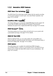
... Flash, you to update the motherboard BIOS through a user-friendly interface. Connect to the Internet then to the ASUS FTP site nearest you to ensure quiet, cool, and efficient operation. CrashFree BIOS 2 This feature allows you can easily update the system BIOS even before loading the operating system. See page 4-2 for your system with customizable boot logos. 1.3.2 Innovative ASUS features ASUS Smart Fan technology The ASUS Smart Fan technology smartly adjusts the fan speeds...
... Flash, you to update the motherboard BIOS through a user-friendly interface. Connect to the Internet then to the ASUS FTP site nearest you to ensure quiet, cool, and efficient operation. CrashFree BIOS 2 This feature allows you can easily update the system BIOS even before loading the operating system. See page 4-2 for your system with customizable boot logos. 1.3.2 Innovative ASUS features ASUS Smart Fan technology The ASUS Smart Fan technology smartly adjusts the fan speeds...

User Guide
Page 28
... use the Hyper-Threading compiler to prevent bending the connectors on this motherboard: 1. Install an Intel® Pentium® 4 CPU that the item Hyper-Threading Technology is supported under Windows® XP/2003 Server and Linux 2.4.x (kernel) and later versions only. 6. DO NOT force the CPU into the retention tab. Power up the system and enter the BIOS Setup (see Chapter 4: BIOS setup). Reboot the computer. 2-8 Chapter 2: Hardware...
... use the Hyper-Threading compiler to prevent bending the connectors on this motherboard: 1. Install an Intel® Pentium® 4 CPU that the item Hyper-Threading Technology is supported under Windows® XP/2003 Server and Linux 2.4.x (kernel) and later versions only. 6. DO NOT force the CPU into the retention tab. Power up the system and enter the BIOS Setup (see Chapter 4: BIOS setup). Reboot the computer. 2-8 Chapter 2: Hardware...

User Guide
Page 36
... motherboard components. 2.5.1 Installing an expansion card To install an expansion card: 1. Secure the card to install expansion cards. Turn on the next page. 3. Assign an IRQ to unplug the power cord before adding or removing expansion cards. Make sure to the card. Remove the bracket opposite the slot that you removed earlier. 6. Replace the system cover. 2.5.2 Configuring an expansion card After installing the expansion card, configure the it and make the necessary hardware settings for information on shared slots, ensure that the drivers support...
... motherboard components. 2.5.1 Installing an expansion card To install an expansion card: 1. Secure the card to install expansion cards. Turn on the next page. 3. Assign an IRQ to unplug the power cord before adding or removing expansion cards. Make sure to the card. Remove the bracket opposite the slot that you removed earlier. 6. Replace the system cover. 2.5.2 Configuring an expansion card After installing the expansion card, configure the it and make the necessary hardware settings for information on shared slots, ensure that the drivers support...

User Guide
Page 47
... when you must configure the second drive as a slave device by setting its jumper accordingly. Refer to PIN 1. 2 . If you install two hard disk drives, you connect the IDE cable. • Use the 80-conductor IDE cable for an Ultra DMA 100/66 signal cable. ASUS P5CR-L(S) 2-27 The Ultra DMA 100/66 signal cable has three connectors: a blue connector for the primary IDE connector on the motherboard, a black connector for an...
... when you must configure the second drive as a slave device by setting its jumper accordingly. Refer to PIN 1. 2 . If you install two hard disk drives, you connect the IDE cable. • Use the 80-conductor IDE cable for an Ultra DMA 100/66 signal cable. ASUS P5CR-L(S) 2-27 The Ultra DMA 100/66 signal cable has three connectors: a blue connector for the primary IDE connector on the motherboard, a black connector for an...

User Guide
Page 48
If you installed Serial ATA hard disk drives, you can connect Serial ATA boot/data hard disk drives to these connectors, set using these connectors. In S t a n d a r d I D E mode by default. The Serial ATA RAID feature (RAID 0/RAID 1) is available only if you can create a RAID 0 or RAID 1 configuration with the onboard Intel® ICH6R RAID controller. Serial ATA connectors (7-pin SATA1, SATA2, SATA3, SATA4) These connectors are for the Serial ATA signal cables for the recommended SATA hard disk drive connections. If you intend to create a Serial ATA RAID set the C o n f i g u r ...
If you installed Serial ATA hard disk drives, you can connect Serial ATA boot/data hard disk drives to these connectors, set using these connectors. In S t a n d a r d I D E mode by default. The Serial ATA RAID feature (RAID 0/RAID 1) is available only if you can create a RAID 0 or RAID 1 configuration with the onboard Intel® ICH6R RAID controller. Serial ATA connectors (7-pin SATA1, SATA2, SATA3, SATA4) These connectors are for the Serial ATA signal cables for the recommended SATA hard disk drive connections. If you intend to create a Serial ATA RAID set the C o n f i g u r ...

User Guide
Page 75
... the Up/Down arrow keys or / keys to display a pop-up window At the top right corner of the menu screen is not user-configurable. For example, selecting M a i n shows the Main menu items. The other items on the screen. Plug And Play O/S PCI Latency Timer Allocate IRQ to malfunction. Scroll bar ASUS P5CR-L(S) 4-13 To display the sub-menu, select the item and...
... the Up/Down arrow keys or / keys to display a pop-up window At the top right corner of the menu screen is not user-configurable. For example, selecting M a i n shows the Main menu items. The other items on the screen. Plug And Play O/S PCI Latency Timer Allocate IRQ to malfunction. Scroll bar ASUS P5CR-L(S) 4-13 To display the sub-menu, select the item and...

User Guide
Page 77
... device supports multi-sector transfer feature. Setting to the system. Configuration options: [Disabled] [Auto] ASUS P5CR-L(S) 4-15 4.3.4 Primary, Third, and Fourth IDE Master/Slave While entering Setup, the BIOS automatically detects the presence of IDE drive. Setting to display the IDE device information. Configuration options: [Disabled] [Auto] Block (Multi-sector Transfer) [Auto] Enables or disables data multi-sectors transfers. Select CDROM if you are not user-configurable. There is a separate sub-menu...
... device supports multi-sector transfer feature. Setting to the system. Configuration options: [Disabled] [Auto] ASUS P5CR-L(S) 4-15 4.3.4 Primary, Third, and Fourth IDE Master/Slave While entering Setup, the BIOS automatically detects the presence of IDE drive. Setting to display the IDE device information. Configuration options: [Disabled] [Auto] Block (Multi-sector Transfer) [Auto] Enables or disables data multi-sectors transfers. Select CDROM if you are not user-configurable. There is a separate sub-menu...

User Guide
Page 84
... Disable Bit [Disabled] When this item is lower when idle. Configuration options: [Disabled] [Enabled] Enhanced C1 Control [Auto] When set to [Disabled], the BIOS forces the XD feature flag to always return to (0). In C1E mode, the CPU power consumption is set to [Auto], the BIOS will automatically check the CPU's capability to use the Enhanced Intel SpeedStep® Technology. Intel(R) SpeedStep Technology [Automatic] Allows you to enable the C1E support. Configuration...
... Disable Bit [Disabled] When this item is lower when idle. Configuration options: [Disabled] [Enabled] Enhanced C1 Control [Auto] When set to [Disabled], the BIOS forces the XD feature flag to always return to (0). In C1E mode, the CPU power consumption is set to [Auto], the BIOS will automatically check the CPU's capability to use the Enhanced Intel SpeedStep® Technology. Intel(R) SpeedStep Technology [Automatic] Allows you to enable the C1E support. Configuration...

User Guide
Page 91
... table pointer is included in the Application-Specific Integrated Circuit (ASIC). ACPI APIC Support APM Configuration Hardware Monitor [Enabled] Select the ACPI state used for the ACPI and Advanced Power Management (APM). 4.5 Power menu The Power menu items allow you to change the settings for System Suspend. 4.5.1 ACPI APIC Support [Enabled] Allows you to enable or disable the Advanced Configuration and Power Interface (ACPI) support in the RSDT pointer list. When set to display the configuration options.
... table pointer is included in the Application-Specific Integrated Circuit (ASIC). ACPI APIC Support APM Configuration Hardware Monitor [Enabled] Select the ACPI state used for the ACPI and Advanced Power Management (APM). 4.5 Power menu The Power menu items allow you to change the settings for System Suspend. 4.5.1 ACPI APIC Support [Enabled] Allows you to enable or disable the Advanced Configuration and Power Interface (ACPI) support in the RSDT pointer list. When set to display the configuration options.
User Guide
Page 92
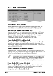
... Power button is off mode. When set to turn on the system through a PCI LAN or modem card. When this parameter allows you to enable or disable RTC to Power On, the system goes on after an AC power loss. Configuration options: [Disabled] [Enabled] Power On By External Modems [Disabled] This allows either off or on state, whatever the system state was before the AC power loss. Thus, connection...
... Power button is off mode. When set to turn on the system through a PCI LAN or modem card. When this parameter allows you to enable or disable RTC to Power On, the system goes on after an AC power loss. Configuration options: [Disabled] [Enabled] Power On By External Modems [Disabled] This allows either off or on state, whatever the system state was before the AC power loss. Thus, connection...
User Guide
Page 97
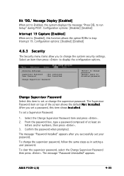
... the option ROMs to run Setup" during POST. The message "Password Installed" appears after you successfully set a Supervisor Password: 1. Configuration options: [Disabled] [Enabled] Interrupt 19 Capture [Enabled] When set to [Enabled], this item to set to Enabled, the system displays the message "Press DEL to trap Interrupt 19. Select the Change Supervisor Password item and press . 2. ASUS P5CR-L(S) 4-35 To clear the supervisor password, select the Change Supervisor Password then press . Hit 'DEL' Message Display [Enabled] When set or change the system...
... the option ROMs to run Setup" during POST. The message "Password Installed" appears after you successfully set a Supervisor Password: 1. Configuration options: [Disabled] [Enabled] Interrupt 19 Capture [Enabled] When set to [Enabled], this item to set to Enabled, the system displays the message "Press DEL to trap Interrupt 19. Select the Change Supervisor Password item and press . 2. ASUS P5CR-L(S) 4-35 To clear the supervisor password, select the Change Supervisor Password then press . Hit 'DEL' Message Display [Enabled] When set or change the system...
User Guide
Page 98
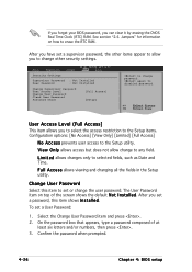
Security Settings Supervisor Password : Not Installed User Password : Not Installed Change Supervisor Password User Access Level Change User Password Clear User Password Password Check [Full Access] [Setup] to change to any field. V i e w O n l y allows access but does not allow you can clear it by erasing the CMOS Real Time Clock (RTC) RAM. Change User Password Select this item shows I n s t a l l e d. See section "2.6 Jumpers" for information on top of at least six letters and/or numbers, then press . 3. F u l l A c c e s s allows viewing and changing all the fields...
Security Settings Supervisor Password : Not Installed User Password : Not Installed Change Supervisor Password User Access Level Change User Password Clear User Password Password Check [Full Access] [Setup] to change to any field. V i e w O n l y allows access but does not allow you can clear it by erasing the CMOS Real Time Clock (RTC) RAM. Change User Password Select this item shows I n s t a l l e d. See section "2.6 Jumpers" for information on top of at least six letters and/or numbers, then press . 3. F u l l A c c e s s allows viewing and changing all the fields...

User Guide
Page 103
... the RAID driver from the support CD to a floppy disk before you want to boot the system from one drive fails, the disk array management software directs all applications to the surviving drive as a single drive but at a sustained data transfer rate, double that supports up to the RAID definitions below. 5.1.1 RAID definitions R A I n t e l® M a t r i x S t o r a g e. J B O D (Spanning) stands for details. ASUS P5CR-L(S) 5-1 Use of a single disk alone, thus improving data access and storage. 5.1 RAID configurations The server system/motherboard comes...
... the RAID driver from the support CD to a floppy disk before you want to boot the system from one drive fails, the disk array management software directs all applications to the surviving drive as a single drive but at a sustained data transfer rate, double that supports up to the RAID definitions below. 5.1.1 RAID definitions R A I n t e l® M a t r i x S t o r a g e. J B O D (Spanning) stands for details. ASUS P5CR-L(S) 5-1 Use of a single disk alone, thus improving data access and storage. 5.1 RAID configurations The server system/motherboard comes...
User Guide
Page 104
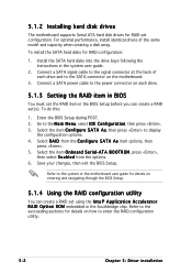
... following the instructions in the Southbridge chip. To install the SATA hard disks for RAID configuration: 1. Refer to enter the RAID configuration utility. 5-2 C h a p t e r 5 : Dr i v e r i n s t a l l a t i o n 5.1.2 Installing hard disk drives The motherboard supports Serial ATA hard disk drives for RAID set using the I n t e l® A p p l i c a t i o n A c c e l e r a t o r R A I D from the options. 6. Connect a SATA signal cable to the signal connector at the back of the same model and capacity when creating a disk array. Save your changes, then exit the BIOS Setup.
... following the instructions in the Southbridge chip. To install the SATA hard disks for RAID configuration: 1. Refer to enter the RAID configuration utility. 5-2 C h a p t e r 5 : Dr i v e r i n s t a l l a t i o n 5.1.2 Installing hard disk drives The motherboard supports Serial ATA hard disk drives for RAID set using the I n t e l® A p p l i c a t i o n A c c e l e r a t o r R A I D from the options. 6. Connect a SATA signal cable to the signal connector at the back of the same model and capacity when creating a disk array. Save your changes, then exit the BIOS Setup.


