P4T533 User Manual
Page 4
... used in this guide iii Safety information vi FCC/CDC statements vii ASUS contact information viii P4T533 specifications summary ix Chapter 1: Product introduction 1 Welcome 1 1.1 Package contents 1 1.2 Core Specifications 2 1.3 Special Features 3 1.4 Motherboard Components 4 1.4.1 Component Locations 5 Chapter 2: Hardware information 7 2.1 Motherboard installation 7 2.1.1 Placement direction 7 2.1.2 Screw holes 7 2.2 Motherboard layout 8 2.2.1 Layout contents 9 2.3 Before you proceed 10 2.4 Central Processing Unit (CPU...
... used in this guide iii Safety information vi FCC/CDC statements vii ASUS contact information viii P4T533 specifications summary ix Chapter 1: Product introduction 1 Welcome 1 1.1 Package contents 1 1.2 Core Specifications 2 1.3 Special Features 3 1.4 Motherboard Components 4 1.4.1 Component Locations 5 Chapter 2: Hardware information 7 2.1 Motherboard installation 7 2.1.1 Placement direction 7 2.1.2 Screw holes 7 2.2 Motherboard layout 8 2.2.1 Layout contents 9 2.3 Before you proceed 10 2.4 Central Processing Unit (CPU...
P4T533 User Manual
Page 12
Special Notice! ASUS P4T533 motherboard Please refer to page 18 for special information about the requirements for the RIMM memory configuration.
Special Notice! ASUS P4T533 motherboard Please refer to page 18 for special information about the requirements for the RIMM memory configuration.
P4T533 User Manual
Page 13
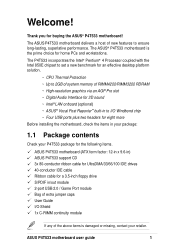
.... Welcome! The P4T533 incorporates the Intel® Pentium® 4 Processor coupled with the Intel 850E chipset to set a new benchmark for an effective desktop platform solution. ~ CPU Thermal Protection ~ Up to 2GB of system memory of RIMM4200/RIMM3200 RDRAM...features to ensure long-lasting, superlative performance. ASUS P4T533 motherboard user guide 1 The ASUS® P4T533 motherboard is damaged or missing, contact your P4T533 package for the following items. ASUS P4T533 motherboard (ATX form factor: 12-in x 9.6-in) ASUS P4T533 support CD 3x 80-conductor ribbon cable for...
.... Welcome! The P4T533 incorporates the Intel® Pentium® 4 Processor coupled with the Intel 850E chipset to set a new benchmark for an effective desktop platform solution. ~ CPU Thermal Protection ~ Up to 2GB of system memory of RIMM4200/RIMM3200 RDRAM...features to ensure long-lasting, superlative performance. ASUS P4T533 motherboard user guide 1 The ASUS® P4T533 motherboard is damaged or missing, contact your P4T533 package for the following items. ASUS P4T533 motherboard (ATX form factor: 12-in x 9.6-in) ASUS P4T533 support CD 3x 80-conductor ribbon cable for...
P4T533 User Manual
Page 14
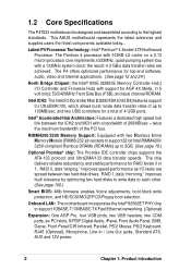
...LAN: The motherboard incorporates the... 4X Mode, (1.5 volt only); 533/400MHz Front Side Bus (FSB); RIMM4200/3200 Memory Support: Equipped with support for a total of up to the highest standards. the result...North Bridge Chipset: the Intel® 850E (82850E Memory Controller Hub,) I/O Controller and Firmware Hub) with two Rambus Inline Memory Module (RIMM) 232-pin sockets to support 32...) features support for RAID levels 0 or 1. and dual channel RDRAM. 1.2 Core Specifications The P4T533 motherboard is designed and assembled according to 2GB. (See page 18.) Optional Promise® chip: The...
...LAN: The motherboard incorporates the... 4X Mode, (1.5 volt only); 533/400MHz Front Side Bus (FSB); RIMM4200/3200 Memory Support: Equipped with support for a total of up to the highest standards. the result...North Bridge Chipset: the Intel® 850E (82850E Memory Controller Hub,) I/O Controller and Firmware Hub) with two Rambus Inline Memory Module (RIMM) 232-pin sockets to support 32...) features support for RAID levels 0 or 1. and dual channel RDRAM. 1.2 Core Specifications The P4T533 motherboard is designed and assembled according to 2GB. (See page 18.) Optional Promise® chip: The...

P4T533 User Manual
Page 16
...19 Promise® RAID / ATA-133 Controller 22 USB 2.0 Controller 23 2 32-bit PC1066/800 Memory RIMMs 4 6 PCI Slots 27 Accelerated Graphics Port (AGP) Pro Slot 32 Floppy Disk Drive Connector...USB 1.1 Connectors (Port 1/2 41 PS/2 Keyboard Connector purple) 42 System Voltage Monitor (integrated in ASUS ASIC 11 Onboard LED 24 Onboard AGP Warning LED 7 Modem Connector 29 RJ45 Connector (optional 35 (... of specifications prevents accidental damage. 1.4 Motherboard Components Before installing the P4T533 motherboard, take time to familiarize yourself with its configuration: understanding the...
...19 Promise® RAID / ATA-133 Controller 22 USB 2.0 Controller 23 2 32-bit PC1066/800 Memory RIMMs 4 6 PCI Slots 27 Accelerated Graphics Port (AGP) Pro Slot 32 Floppy Disk Drive Connector...USB 1.1 Connectors (Port 1/2 41 PS/2 Keyboard Connector purple) 42 System Voltage Monitor (integrated in ASUS ASIC 11 Onboard LED 24 Onboard AGP Warning LED 7 Modem Connector 29 RJ45 Connector (optional 35 (... of specifications prevents accidental damage. 1.4 Motherboard Components Before installing the P4T533 motherboard, take time to familiarize yourself with its configuration: understanding the...
P4T533 User Manual
Page 18
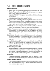
... the system to sleep mode or to soft-off mode regardless of the BIOS setting. A chassis intrusion event is in the system memory for more protection. (See page 40.) 1.5 Value-added solutions Easy Overclocking • Quickly adjust CPU frequency multiples with 1.1 USB,...See page 27 and 66.) Temperature, Fan and Voltage Monitoring: ASUS ASIC and the CPU's internal thermal diode monitors temperature to prevent overheating. Chassis intrusion detection The motherboard supports chassis intrusion monitoring through the ASUS ASIC. optionally bundled) for less than 4 seconds lets the ...
... the system to sleep mode or to soft-off mode regardless of the BIOS setting. A chassis intrusion event is in the system memory for more protection. (See page 40.) 1.5 Value-added solutions Easy Overclocking • Quickly adjust CPU frequency multiples with 1.1 USB,...See page 27 and 66.) Temperature, Fan and Voltage Monitoring: ASUS ASIC and the CPU's internal thermal diode monitors temperature to prevent overheating. Chassis intrusion detection The motherboard supports chassis intrusion monitoring through the ASUS ASIC. optionally bundled) for less than 4 seconds lets the ...
P4T533 User Manual
Page 22
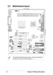
These components are optional. PRIMARY IDE SECONDARY IDE 30.5cm (12.0in) 2.2 Motherboard layout PS/2KBMS T: Mouse B: Keyboard USB1.1 T: USB1 B: USB2 COM1 KBPWR USBPWR01 OVER_VOLT 24.5cm (9.6in) RIMMA (32 bit, 232-pin module) RIMMB (32 bit, ... LINE_IN LO_L LO_R BCS2 BCS1 SPDIF_C LED1 Intel LAN Controller Socket 478 Intel 850E Memory Controller Hub (MCH) TRPWR CPU_FAN ATX12V DSWF Accelerated Graphics Port AGP PCI1 Intel I/O Controller Hub (ICH2) CLCMOS ASUS ASIC with Hardware Monitor PCI2 PCI3 P4T533 PCI4 ® PCI5 PCI6 CR2032 3V Lithium Cell CMOS Power SEC_RAID Super I/O ...
These components are optional. PRIMARY IDE SECONDARY IDE 30.5cm (12.0in) 2.2 Motherboard layout PS/2KBMS T: Mouse B: Keyboard USB1.1 T: USB1 B: USB2 COM1 KBPWR USBPWR01 OVER_VOLT 24.5cm (9.6in) RIMMA (32 bit, 232-pin module) RIMMB (32 bit, ... LINE_IN LO_L LO_R BCS2 BCS1 SPDIF_C LED1 Intel LAN Controller Socket 478 Intel 850E Memory Controller Hub (MCH) TRPWR CPU_FAN ATX12V DSWF Accelerated Graphics Port AGP PCI1 Intel I/O Controller Hub (ICH2) CLCMOS ASUS ASIC with Hardware Monitor PCI2 PCI3 P4T533 PCI4 ® PCI5 PCI6 CR2032 3V Lithium Cell CMOS Power SEC_RAID Super I/O ...

P4T533 User Manual
Page 23
... Expansion Slots 1) Socket 478 p. 12 Installing the CPU 2) Heatsink p. 13 Installing the Heatsink and Fan 3) Memory p. 16 System Memory Support 4) PCI 1/2/3/4/5/6 p. 19 32-bit PCI Bus Expansion Slots 5) AGP Pro p. 21 Accelerated Graphics Slot Motherboard Settings (Switches and Jumpers) 1) JEN p. 22 JumperFree Mode Setting (Disable/Enable) 2) DSW1 p. 23 CPU External Frequency ... p. 39 USB 2.0 Headers (10-1 pin) 17) CD, AUX, MODEM p. 40 Internal Audio Connectors (Three 4-1 pin) (optional) 18) CHASSIS p. 40 Chassis Open Alarm Lead (4-1 pin) ASUS P4T533 motherboard user guide 9
... Expansion Slots 1) Socket 478 p. 12 Installing the CPU 2) Heatsink p. 13 Installing the Heatsink and Fan 3) Memory p. 16 System Memory Support 4) PCI 1/2/3/4/5/6 p. 19 32-bit PCI Bus Expansion Slots 5) AGP Pro p. 21 Accelerated Graphics Slot Motherboard Settings (Switches and Jumpers) 1) JEN p. 22 JumperFree Mode Setting (Disable/Enable) 2) DSW1 p. 23 CPU External Frequency ... p. 39 USB 2.0 Headers (10-1 pin) 17) CD, AUX, MODEM p. 40 Internal Audio Connectors (Three 4-1 pin) (optional) 18) CHASSIS p. 40 Chassis Open Alarm Lead (4-1 pin) ASUS P4T533 motherboard user guide 9

P4T533 User Manual
Page 30
2.5 System memory 2.5.1 Overview This motherboard has two 232-pin Rambus Inline Memory Modules (RIMM) sockets. A C-RIMM is not populated by RDRAMs. To assure the electrical integrity of the Rambus interface. The diagram below shows the various ...combinations for inserting RIMMs.) a. These sockets support 32-bit RIMMs in the following sizes: 128, 256 and 512Mbit RDRAM RIMMs. Location Memory Module Subtotal RIMM1 (Rows 0&1) RDRAM x 1 and/or C-RIMM (Use when socket is unpopulated.) RIMM2 (Rows 2&3) RDRAM x 1 and/or C-RIMM (Use when socket is unpopulated.)...
2.5 System memory 2.5.1 Overview This motherboard has two 232-pin Rambus Inline Memory Modules (RIMM) sockets. A C-RIMM is not populated by RDRAMs. To assure the electrical integrity of the Rambus interface. The diagram below shows the various ...combinations for inserting RIMMs.) a. These sockets support 32-bit RIMMs in the following sizes: 128, 256 and 512Mbit RDRAM RIMMs. Location Memory Module Subtotal RIMM1 (Rows 0&1) RDRAM x 1 and/or C-RIMM (Use when socket is unpopulated.) RIMM2 (Rows 2&3) RDRAM x 1 and/or C-RIMM (Use when socket is unpopulated.)...
P4T533 User Manual
Page 31
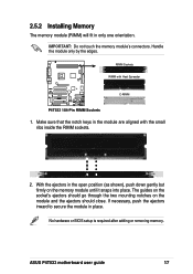
No hardware or BIOS setup is required after adding or removing memory. The guides on the socket's ejectors should close. ASUS P4T533 motherboard user guide 17 IMPORTANT: Do not touch the memory module's connectors. Handle the module only by the edges. Make sure that the notch keys in... ejectors should go through the two mounting notches on the memory module until it snaps into place. With the ejectors in place. 2.5.2 Installing Memory The memory module (RIMM) will fit in the module are aligned with Heat Spreader P4T533 ® C-RIMM P4T533 184-Pin RIMM Sockets 1.
No hardware or BIOS setup is required after adding or removing memory. The guides on the socket's ejectors should close. ASUS P4T533 motherboard user guide 17 IMPORTANT: Do not touch the memory module's connectors. Handle the module only by the edges. Make sure that the notch keys in... ejectors should go through the two mounting notches on the memory module until it snaps into place. With the ejectors in place. 2.5.2 Installing Memory The memory module (RIMM) will fit in the module are aligned with Heat Spreader P4T533 ® C-RIMM P4T533 184-Pin RIMM Sockets 1.
P4T533 User Manual
Page 32
...to cool off before removing them. 2.5.4 General RIMM Memos: 32-bit 1066/800MHz RIMM Qualified Vendor List The following table lists qualified memory modules that have been tested and for use with 400MHz CPUs. 18 Chapter 2: Hardware information RIMMs manufactured by other vendors may not be... suitable for more updates: http://www.asus.com RIMM4200 modules require use RIMM4200 modules with this motherboard. therefore,do not use of 533MHz CPUs; To reduce the risk of the RIMM sockets. Visit the...
...to cool off before removing them. 2.5.4 General RIMM Memos: 32-bit 1066/800MHz RIMM Qualified Vendor List The following table lists qualified memory modules that have been tested and for use with 400MHz CPUs. 18 Chapter 2: Hardware information RIMMs manufactured by other vendors may not be... suitable for more updates: http://www.asus.com RIMM4200 modules require use RIMM4200 modules with this motherboard. therefore,do not use of 533MHz CPUs; To reduce the risk of the RIMM sockets. Visit the...

P4T533 User Manual
Page 43
... to re-enter data. You can clear the CMOS memory of date, time, and system setup parameters by erasing the CMOS RTC RAM data. Turn OFF the computer and unplug the power cord. 2. P4T533 ® P4T533 Clear RTC RAM CLRTC Short jumper to clear CMOS ASUS P4T533 motherboard user guide 29 11. Re-install the battery. 6.
... to re-enter data. You can clear the CMOS memory of date, time, and system setup parameters by erasing the CMOS RTC RAM data. Turn OFF the computer and unplug the power cord. 2. P4T533 ® P4T533 Clear RTC RAM CLRTC Short jumper to clear CMOS ASUS P4T533 motherboard user guide 29 11. Re-install the battery. 6.
P4T533 User Manual
Page 63
... runs the power-on the devices in the following order: a. Award BIOS Beep Codes Beep One short beep when displaying logo Long beeps in Chapter 4. ASUS P4T533 motherboard user guide 47 Turn on tests. Connect the power cord to a power outlet that all the connections, replace the system case cover. 2. Be sure ...that is working Meaning No error during POST No DRAM installed or detected Video card not found or video card memory bad CPU overheated; Check the jumper settings and connections or call your monitor complies with a surge protector. 5.
... runs the power-on the devices in the following order: a. Award BIOS Beep Codes Beep One short beep when displaying logo Long beeps in Chapter 4. ASUS P4T533 motherboard user guide 47 Turn on tests. Connect the power cord to a power outlet that all the connections, replace the system case cover. 2. Be sure ...that is working Meaning No error during POST No DRAM installed or detected Video card not found or video card memory bad CPU overheated; Check the jumper settings and connections or call your monitor complies with a surge protector. 5.
P4T533 User Manual
Page 64
.... These POST messages are not defective. • Refer to the recommended settings. You can record your package. 3.2 Vocal POST Messages This motherboard includes the Winbond speech controller to section "2.7 Jumpers." 48 Chapter 3: Powering up See section "4.4 Advanced menu." • In jumper mode,... refer to support a special feature called the ASUS POST Reporter™. POST Message No CPU installed System failed CPU test System failed memory test System failed VGA test System failed due to CPU over-clocking Action • Install ...
.... These POST messages are not defective. • Refer to the recommended settings. You can record your package. 3.2 Vocal POST Messages This motherboard includes the Winbond speech controller to section "2.7 Jumpers." 48 Chapter 3: Powering up See section "4.4 Advanced menu." • In jumper mode,... refer to support a special feature called the ASUS POST Reporter™. POST Message No CPU installed System failed CPU test System failed memory test System failed VGA test System failed due to CPU over-clocking Action • Install ...
P4T533 User Manual
Page 71
... DOS mode, type A:\AFLASH to the disk. 2. If the word "unknown" appears after Flash Memory:, the memory chip is either not programmable or is not supported by the Flash Memory Writer utility. 5. ASUS P4T533 motherboard user guide 53 DO NOT copy AUTOEXEC.BAT and CONFIG.SYS to run AFLASH. BIOS setup must ...be loaded when you reboot using a floppy disk. It does not function in the DOS prompt within Windows, and does not function with certain memory drivers that you boot from the Main menu and press . 4.1.2 Using AFLASH from the floppy disk. NOTE! Save Current BIOS to create a...
... DOS mode, type A:\AFLASH to the disk. 2. If the word "unknown" appears after Flash Memory:, the memory chip is either not programmable or is not supported by the Flash Memory Writer utility. 5. ASUS P4T533 motherboard user guide 53 DO NOT copy AUTOEXEC.BAT and CONFIG.SYS to run AFLASH. BIOS setup must ...be loaded when you reboot using a floppy disk. It does not function in the DOS prompt within Windows, and does not function with certain memory drivers that you boot from the Main menu and press . 4.1.2 Using AFLASH from the floppy disk. NOTE! Save Current BIOS to create a...

P4T533 User Manual
Page 73
... the possibility of boot problems in case of update failures. If you saved to the boot disk. 7. ASUS P4T533 motherboard user guide 55 When the programming is updated automatically only when necessary. If the Flash Memory Writer utility is not able to successfully update a complete BIOS file, the system may cause boot problems. Just...
... the possibility of boot problems in case of update failures. If you saved to the boot disk. 7. ASUS P4T533 motherboard user guide 55 When the programming is updated automatically only when necessary. If the Flash Memory Writer utility is not able to successfully update a complete BIOS file, the system may cause boot problems. Just...
P4T533 User Manual
Page 83
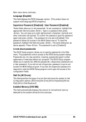
...: a Supervisor password and a User password. If you did not set a Supervisor password, anyone can type up to [Enabled]. ASUS P4T533 motherboard user guide 65 Main menu items continued... The password is set to eight alphanumeric characters. This password allows full access to the configuration... to set a password, highlight the appropriate field and press . Halt On [All Errors] This field specifies the types of conventional memory detected by the system during system startup. Press . If you to [Disabled]. Type in either uppercase or lowercase letters are accepted....
...: a Supervisor password and a User password. If you did not set a Supervisor password, anyone can type up to [Enabled]. ASUS P4T533 motherboard user guide 65 Main menu items continued... The password is set to eight alphanumeric characters. This password allows full access to the configuration... to set a password, highlight the appropriate field and press . Halt On [All Errors] This field specifies the types of conventional memory detected by the system during system startup. Press . If you to [Disabled]. Type in either uppercase or lowercase letters are accepted....
P4T533 User Manual
Page 84
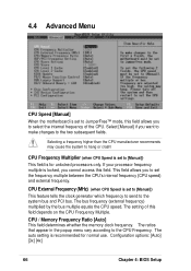
...] [3x] [4x] 66 Chapter 4: BIOS Setup This field allows you want to make changes to the two subsequent fields. CPU / Memory Frequency Ratio [Auto] This field determines whether the memory clock frequency. The ratios that appear in the popup menu vary according to hang or crash! Select [Manual] if you to...]) This feature tells the clock generator which frequency to send to the system bus and PCI bus. 4.4 Advanced Menu CPU Speed [Manual] When the motherboard is set to JumperFree™ mode, this field allows you cannot access this field depends on the CPU Frequency Multiple.
...] [3x] [4x] 66 Chapter 4: BIOS Setup This field allows you want to make changes to the two subsequent fields. CPU / Memory Frequency Ratio [Auto] This field determines whether the memory clock frequency. The ratios that appear in the popup menu vary according to hang or crash! Select [Manual] if you to...]) This feature tells the clock generator which frequency to send to the system bus and PCI bus. 4.4 Advanced Menu CPU Speed [Manual] When the motherboard is set to JumperFree™ mode, this field allows you cannot access this field depends on the CPU Frequency Multiple.
P4T533 User Manual
Page 86
...loads the update on or off the CPU Level 1 and Level 2 built-in cache. Configuration options: [Enabled] [Auto] USB Legacy Support [Auto] This motherboard supports Universal Serial Bus (USB) devices. When you need to turn on all processors during system bootup. Configuration options: [Disabled] [Enabled] BIOS Update [... processor with installed DRAM of [Enabled] or choose [Disabled] to set this field. Configuration options: [Disabled] [Enabled] [Auto] OS/2 Onboard Memory > 64M [Disabled] When using a USB device. Configuration options: [Disabled] [Enabled] 68 Chapter 4: BIOS Setup
...loads the update on or off the CPU Level 1 and Level 2 built-in cache. Configuration options: [Enabled] [Auto] USB Legacy Support [Auto] This motherboard supports Universal Serial Bus (USB) devices. When you need to turn on all processors during system bootup. Configuration options: [Disabled] [Enabled] BIOS Update [... processor with installed DRAM of [Enabled] or choose [Disabled] to set this field. Configuration options: [Disabled] [Enabled] [Auto] OS/2 Onboard Memory > 64M [Disabled] When using a USB device. Configuration options: [Disabled] [Enabled] 68 Chapter 4: BIOS Setup

P4T533 User Manual
Page 87
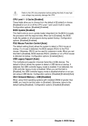
... system components. Expansion cards can also set this feature, otherwise the system may not boot. Configuration options: [UC] [USWC] Memory Hole At 15M-16M [Disabled] This field allows you to UC (uncacheable) if your display card does not support this to ...select the size of mapped memory for the video memory of the RDRAM memory. 4.4.1 Chip Configuration RDRAM Turbo Mode This feature maximizes the performance of the processor. You must set both . Configuration options: [Both] [Primary] [Secondary] [Disabled] ASUS P4T533 motherboard user guide 69 It can greatly...
... system components. Expansion cards can also set this feature, otherwise the system may not boot. Configuration options: [UC] [USWC] Memory Hole At 15M-16M [Disabled] This field allows you to UC (uncacheable) if your display card does not support this to ...select the size of mapped memory for the video memory of the RDRAM memory. 4.4.1 Chip Configuration RDRAM Turbo Mode This feature maximizes the performance of the processor. You must set both . Configuration options: [Both] [Primary] [Secondary] [Disabled] ASUS P4T533 motherboard user guide 69 It can greatly...


