
User Manual
Page 1
® P4T-F Intel® 850 ATX Motherboard USER'S MANUAL
® P4T-F Intel® 850 ATX Motherboard USER'S MANUAL
User Manual
Page 4
... Configuration 63 4.4.3 PCI Configuration 65 4.4.4 Shadow Configuration 67 4.5 Power Menu 68 4 ASUS P4T-F User's Manual CONTENTS 1. FEATURES 8 2.1 The ASUS P4T-F 8 2.2 P4T-F Motherboard Components 12 3. INTRODUCTION 7 1.1 How This Manual Is Organized 7 1.2 Item Checklist 7 2. HARDWARE SETUP 14 3.1 P4T-F Motherboard Layout 14 3.2 Layout Contents 15 3.3 Hardware Setup Procedure 16 3.4 Motherboard Settings 17 3.5 System Memory 23 3.5.1 CPU Installation 25 3.5 Central Processing Unit (CPU...
... Configuration 63 4.4.3 PCI Configuration 65 4.4.4 Shadow Configuration 67 4.5 Power Menu 68 4 ASUS P4T-F User's Manual CONTENTS 1. FEATURES 8 2.1 The ASUS P4T-F 8 2.2 P4T-F Motherboard Components 12 3. INTRODUCTION 7 1.1 How This Manual Is Organized 7 1.2 Item Checklist 7 2. HARDWARE SETUP 14 3.1 P4T-F Motherboard Layout 14 3.2 Layout Contents 15 3.3 Hardware Setup Procedure 16 3.4 Motherboard Settings 17 3.5 System Memory 23 3.5.1 CPU Installation 25 3.5 Central Processing Unit (CPU...
User Manual
Page 5
SOFTWARE SETUP 77 5.1 Install Operating System 77 5.2 Start Windows 77 5.3 P4T-F Motherboard Support CD 78 6. APPENDIX 89 7.1 Glossary 89 INDEX 95 ASUS P4T-F User's Manual 5 CONTENTS 4.5.1 Power Up Control 70 4.5.2 Hardware Monitor 71 4.6 Boot Menu 72 4.7 Exit Menu 74 5. SOFTWARE REFERENCE 80 6.1 ASUS Live Update 80 6.2 ASUS PC Probe 81 6.3 CyberLink PowerPlayer SE 86 6.4 CyberLink VideoLive Mail 87 7.
SOFTWARE SETUP 77 5.1 Install Operating System 77 5.2 Start Windows 77 5.3 P4T-F Motherboard Support CD 78 6. APPENDIX 89 7.1 Glossary 89 INDEX 95 ASUS P4T-F User's Manual 5 CONTENTS 4.5.1 Power Up Control 70 4.5.2 Hardware Monitor 71 4.6 Boot Menu 72 4.7 Exit Menu 74 5. SOFTWARE REFERENCE 80 6.1 ASUS Live Update 80 6.2 ASUS PC Probe 81 6.3 CyberLink PowerPlayer SE 86 6.4 CyberLink VideoLive Mail 87 7.
User Manual
Page 7
... USB connector set with bracket (1) Bag of spare jumpers (1) Support drivers and utilities (1) This Motherboard User's Manual (1) CPU Retention Module (2) ASUS C-RIMM Continuity RIMM Optional Items ASUS IrDA-compliant infrared module Rambus LAN Card 1394 Card ASUS P4T-F User's Manual 7 INTRODUCTION 2. INTRODUCTION Manual / Checklist 1. If you discover damaged or missing items, contact your package is...
... USB connector set with bracket (1) Bag of spare jumpers (1) Support drivers and utilities (1) This Motherboard User's Manual (1) CPU Retention Module (2) ASUS C-RIMM Continuity RIMM Optional Items ASUS IrDA-compliant infrared module Rambus LAN Card 1394 Card ASUS P4T-F User's Manual 7 INTRODUCTION 2. INTRODUCTION Manual / Checklist 1. If you discover damaged or missing items, contact your package is...

User Manual
Page 8
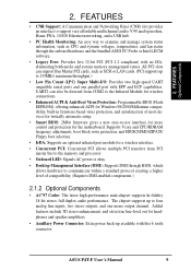
2. FEATURES Performance 2. The slot is keyed to support only the latest 1.5 volt AGP cards: i.e.: ASUS V3800 and newer versions. • JumperFree™ Mode: Now processor settings and easy overclocking of frequency and Vcore voltage can be controlled through ...'s Manual and two USB controllers for AGP 4X Pro Mode, (1.5 volt only); 400MHz Front Side Bus (FSB); FEATURES 2.1 The ASUS P4T-F The ASUS P4T-F motherboard is required. • Intel® Accelerated Hub Architecture: Features a dedicated high speed hub link between the ICH2 and MCH with a bandwidth of 4 USB ports. &#...
2. FEATURES Performance 2. The slot is keyed to support only the latest 1.5 volt AGP cards: i.e.: ASUS V3800 and newer versions. • JumperFree™ Mode: Now processor settings and easy overclocking of frequency and Vcore voltage can be controlled through ...'s Manual and two USB controllers for AGP 4X Pro Mode, (1.5 volt only); 400MHz Front Side Bus (FSB); FEATURES 2.1 The ASUS P4T-F The ASUS P4T-F motherboard is required. • Intel® Accelerated Hub Architecture: Features a dedicated high speed hub link between the ICH2 and MCH with a bandwidth of 4 USB ports. &#...
User Manual
Page 9
... interface. • Concurrent PCI: Concurrent PCI allows multiple PCI transfers from COM2 to -use interface for more control and protection for the motherboard. All PCI slots can also be directed from PCI master bus to the memory and processor. • Onboard LED: Signals AC power ... to four analog line inputs, two stereo outputs, and one parallel port with no ISA, eliminating bottlenecks and system memory management issues. ASUS P4T-F User's Manual 9 Added featuers include 3D stereo enhancement, and extra true line-level out for Windows 98/2000/Millenium compatibility, built...
... interface. • Concurrent PCI: Concurrent PCI allows multiple PCI transfers from COM2 to -use interface for more control and protection for the motherboard. All PCI slots can also be directed from PCI master bus to the memory and processor. • Onboard LED: Signals AC power ... to four analog line inputs, two stereo outputs, and one parallel port with no ISA, eliminating bottlenecks and system memory management issues. ASUS P4T-F User's Manual 9 Added featuers include 3D stereo enhancement, and extra true line-level out for Windows 98/2000/Millenium compatibility, built...
User Manual
Page 10
... more Energy Saving Features for Windows 95/NT and later. The new PC 99 requirements for systems and components are based on all ASUS smart series motherboards. Supports UltraDMA/100/66, UltraDMA/33 (IDE DMA Mode 2), PIO Modes 3 & 4, and supports Enhanced IDE devices, such as... required by PC 99. 10 ASUS P4T-F User's Manual With these features implemented in two channels. Color-coded connectors and descriptive icons make identification easy as ...
... more Energy Saving Features for Windows 95/NT and later. The new PC 99 requirements for systems and components are based on all ASUS smart series motherboards. Supports UltraDMA/100/66, UltraDMA/33 (IDE DMA Mode 2), PIO Modes 3 & 4, and supports Enhanced IDE devices, such as... required by PC 99. 10 ASUS P4T-F User's Manual With these features implemented in two channels. Color-coded connectors and descriptive icons make identification easy as ...
User Manual
Page 11
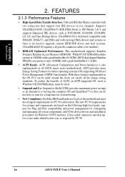
... cycle when temperature lowers to prevent possible application crashes. 2. FEATURES Intelligence 2. Voltage specifications are set for more information) button. ASUS P4T-F User's Manual 11 When auto throttling is a new technology to be powered ON using your keyboard or mouse click. Suggestions will...range and alarm thresholds. • Temperature Monitoring andAlert: To prevent system overheat and system damage, this motherboard is enabled, the CPU with either the bundled ASUS PC Probe or Intel LDCM will enter the Soft-Off mode. • Peripheral Power Up: Keyboard or...
... cycle when temperature lowers to prevent possible application crashes. 2. FEATURES Intelligence 2. Voltage specifications are set for more information) button. ASUS P4T-F User's Manual 11 When auto throttling is a new technology to be powered ON using your keyboard or mouse click. Suggestions will...range and alarm thresholds. • Temperature Monitoring andAlert: To prevent system overheat and system damage, this motherboard is enabled, the CPU with either the bundled ASUS PC Probe or Intel LDCM will enter the Soft-Off mode. • Peripheral Power Up: Keyboard or...
User Manual
Page 12
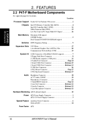
Location Processor Support Socket 423 for locations. FEATURES MB Components 2. 2. FEATURES 2.2 P4T-F Motherboard Components See opposite page for Pentium 4 Processors 2 Chipsets Intel 850 Memory Controller Hub (MCH 4 Intel I/O Controller Hub 2 (ICH2 11 ...Game/MIDI Connector Top) 22 1 Line Out Connector Bottom) 22 1 Line In Connector Bottom) 22 1 Line Microphone Connector Bottom) 22 Hardware Monitoring ASUS onboard chipset 10 Power ATX Power Supply Connector 1 ATX 12V Power Supply Connector 3 Special Feature Auxillary Power Connector 6 Onboard LED 14 Form Factor ATX...
Location Processor Support Socket 423 for locations. FEATURES MB Components 2. 2. FEATURES 2.2 P4T-F Motherboard Components See opposite page for Pentium 4 Processors 2 Chipsets Intel 850 Memory Controller Hub (MCH 4 Intel I/O Controller Hub 2 (ICH2 11 ...Game/MIDI Connector Top) 22 1 Line Out Connector Bottom) 22 1 Line In Connector Bottom) 22 1 Line Microphone Connector Bottom) 22 Hardware Monitoring ASUS onboard chipset 10 Power ATX Power Supply Connector 1 ATX 12V Power Supply Connector 3 Special Feature Auxillary Power Connector 6 Onboard LED 14 Form Factor ATX...
User Manual
Page 14
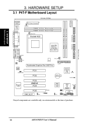
... 30.5cm (12.0in) AUX Power Connector 3. HARDWARE SETUP 3.1 P4T-F Motherboard Layout PS/2KBMS T: Mouse B: Keyboard USB T: Port1 B: Port2 COM1 24.4cm (9.60in) ATX Power Connector USBPWR RIMMB2 (16/18 bit, 184-pin module) RIMMB1 (16/...) Audio Codec HEADPHONE PCI1 PCI2 CR2032 3V Lithium Cell CMOS Power Intel I/O Controller Hub (ICH2) CLRTC HDDLED Super I/O PCI3 P4T-F PCI4 PCI5 LED CNR_SLOT IR ADN 2Mbit Firmware Hub J3J3+ USB2 ASUS ASIC with Hardware Monitor PCI_FAN JEN DIP Switches OC3 CHASSIS PANEL Grayed components are available only on certain models at...
... 30.5cm (12.0in) AUX Power Connector 3. HARDWARE SETUP 3.1 P4T-F Motherboard Layout PS/2KBMS T: Mouse B: Keyboard USB T: Port1 B: Port2 COM1 24.4cm (9.60in) ATX Power Connector USBPWR RIMMB2 (16/18 bit, 184-pin module) RIMMB1 (16/...) Audio Codec HEADPHONE PCI1 PCI2 CR2032 3V Lithium Cell CMOS Power Intel I/O Controller Hub (ICH2) CLRTC HDDLED Super I/O PCI3 P4T-F PCI4 PCI5 LED CNR_SLOT IR ADN 2Mbit Firmware Hub J3J3+ USB2 ASUS ASIC with Hardware Monitor PCI_FAN JEN DIP Switches OC3 CHASSIS PANEL Grayed components are available only on certain models at...
User Manual
Page 15
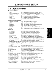
... Management Interrupt Switch Lead (2 pin) 23) PWRSW (PANEL) p.41 ATX Power / Soft-Off Switch Lead (2 pin) 24) RESET (PANEL) p.41 Reset Switch Lead (2 pin) ASUS P4T-F User's Manual 15 Freq. 3. H/W SETUP Layout Contents 3. HARDWARE SETUP 3.2 Layout Contents Motherboard Settings 1) JEN p. 18 JumperFree™ Mode (JEN) (Disable / Enable) 2) SW1 (Switches 6-10) p. 19 CPU Ext.
... Management Interrupt Switch Lead (2 pin) 23) PWRSW (PANEL) p.41 ATX Power / Soft-Off Switch Lead (2 pin) 24) RESET (PANEL) p.41 Reset Switch Lead (2 pin) ASUS P4T-F User's Manual 15 Freq. 3. H/W SETUP Layout Contents 3. HARDWARE SETUP 3.2 Layout Contents Motherboard Settings 1) JEN p. 18 JumperFree™ Mode (JEN) (Disable / Enable) 2) SW1 (Switches 6-10) p. 19 CPU Ext.
User Manual
Page 16
... supply when adding or removing system components. Check motherboard settings 2. H/W SETUP Getting Started 16 ASUS P4T-F User's Manual For typical system configurations, an ATX12V power supply that can supply at least 230W and at least 300W is recommended for this motherboard. Make sure that you unplug your motherboard, peripherals, and/or components. 3. Install memory modules...
... supply when adding or removing system components. Check motherboard settings 2. H/W SETUP Getting Started 16 ASUS P4T-F User's Manual For typical system configurations, an ATX12V power supply that can supply at least 230W and at least 300W is recommended for this motherboard. Make sure that you unplug your motherboard, peripherals, and/or components. 3. Install memory modules...

User Manual
Page 17
... or remove the ATX power connector on the bag that the ATX power supply is switched off before handling computer components. H/W SETUP Motherboard Settings ASUS P4T-F User's Manual 17 Place components on a grounded antistatic pad or on the motherboard. Use a grounded wrist strap before you work on the inside. 2. If you how to change...
... or remove the ATX power connector on the bag that the ATX power supply is switched off before handling computer components. H/W SETUP Motherboard Settings ASUS P4T-F User's Manual 17 Place components on a grounded antistatic pad or on the motherboard. Use a grounded wrist strap before you work on the inside. 2. If you how to change...
User Manual
Page 18
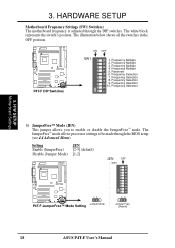
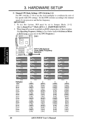
... SW1 ON 1 2 3 4 5 6 7 8 9 10 P4T-F 12 Jumper Mode P4T-F JumperFree™ Mode Setting 23 Jumper Free (Default) 18 ASUS P4T-F User's Manual P4T-F P4T-F DIP Switches ON 1 2 3 4 5 6 7 8 9 10 ON OFF SW1 1. Frequency Multiple 3. Frequency Selection 10. H/W SETUP Motherboard Settings 1) JumperFree™ Mode (JEN) This jumper allows you to... below shows all the switches in the OFF position. Frequency Multiple 5. 3. HARDWARE SETUP Motherboard Frequency Settings (SW1 Switches) The motherboard frequency is adjusted through the BIOS setup (see 4.4 Advanced Menu). Frequency Selection 3.
... SW1 ON 1 2 3 4 5 6 7 8 9 10 P4T-F 12 Jumper Mode P4T-F JumperFree™ Mode Setting 23 Jumper Free (Default) 18 ASUS P4T-F User's Manual P4T-F P4T-F DIP Switches ON 1 2 3 4 5 6 7 8 9 10 ON OFF SW1 1. Frequency Multiple 3. Frequency Selection 10. H/W SETUP Motherboard Settings 1) JumperFree™ Mode (JEN) This jumper allows you to... below shows all the switches in the OFF position. Frequency Multiple 5. 3. HARDWARE SETUP Motherboard Frequency Settings (SW1 Switches) The motherboard frequency is adjusted through the BIOS setup (see 4.4 Advanced Menu). Frequency Selection 3.
User Manual
Page 19
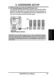
... other than the recommended CPU bus frequencies are not guaranteed to the CPU, DRAM, and the PCI bus. ASUS P4T-F User's Manual 19 The BUS Clock multiplied by the Frequency Multiple equals the CPU's Internal frequency (the advertised... CPU speed). It may result in a slower speed. SW1 P4T-F P4T-F CPU External Frequency Selection CPU 100.0MHz 103.0MHz 105.0MHz 110.0MHz AGP 66.0MHz 68.0MHz...BUS Clock). ON 1 2 3 4 5 6 7 8 9 10 ON 1 2 3 4 5 6 7 8 9 10 ON 1 2 3 4 5 6 7 8 9 10 ON 1 2 3 4 5 6 7 8 9 10 3. H/W SETUP Motherboard Settings 3.
... other than the recommended CPU bus frequencies are not guaranteed to the CPU, DRAM, and the PCI bus. ASUS P4T-F User's Manual 19 The BUS Clock multiplied by the Frequency Multiple equals the CPU's Internal frequency (the advertised... CPU speed). It may result in a slower speed. SW1 P4T-F P4T-F CPU External Frequency Selection CPU 100.0MHz 103.0MHz 105.0MHz 110.0MHz AGP 66.0MHz 68.0MHz...BUS Clock). ON 1 2 3 4 5 6 7 8 9 10 ON 1 2 3 4 5 6 7 8 9 10 ON 1 2 3 4 5 6 7 8 9 10 ON 1 2 3 4 5 6 7 8 9 10 3. H/W SETUP Motherboard Settings 3.
User Manual
Page 20
... 3) Manual CPU Ratio Settings (SW1 Switches 1-4) Set SW1 switches (7-10) to coordinate the ratio of your processor and the bus frequency. 3. H/W SETUP Motherboard Settings P4T-F CPU External Clock (BUS) Frequency P4T-F Selection ON ON ON ON 1 2 3 4 5 6 7 8 9 10 8.0x ON 1 2 3 4 5 6 7 8 9 10 13.0x ON 1 2 3 4 5 6 7 8 9 10 17.0x ...] [OFF] [OFF] [OFF] [OFF] [OFF] [OFF] [ON] [ON] [ON] [ON] [ON] [ON] [ON] [ON] 20 ASUS P4T-F User's Manual Set the DSW switches according to Jumper Mode, [1-2]. (See 1, JumperFree™ Mode (JEN) in 3, HARDWARE SETUP.) 2. When JumperFree mode is...
... 3) Manual CPU Ratio Settings (SW1 Switches 1-4) Set SW1 switches (7-10) to coordinate the ratio of your processor and the bus frequency. 3. H/W SETUP Motherboard Settings P4T-F CPU External Clock (BUS) Frequency P4T-F Selection ON ON ON ON 1 2 3 4 5 6 7 8 9 10 8.0x ON 1 2 3 4 5 6 7 8 9 10 13.0x ON 1 2 3 4 5 6 7 8 9 10 17.0x ...] [OFF] [OFF] [OFF] [OFF] [OFF] [OFF] [ON] [ON] [ON] [ON] [ON] [ON] [ON] [ON] 20 ASUS P4T-F User's Manual Set the DSW switches according to Jumper Mode, [1-2]. (See 1, JumperFree™ Mode (JEN) in 3, HARDWARE SETUP.) 2. When JumperFree mode is...
User Manual
Page 21
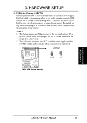
... consumed must NOT exceed the power supply capability (+5VSB) whether under normal working conditions or in low power mode) using the connected USB devices. H/W SETUP Motherboard Settings ASUS P4T-F User's Manual 21 HARDWARE SETUP 4) USB Device Wake-up from S3 sleep state (no power to +5VSB. RAM in reduced power mode). Otherwise, the...
... consumed must NOT exceed the power supply capability (+5VSB) whether under normal working conditions or in low power mode) using the connected USB devices. H/W SETUP Motherboard Settings ASUS P4T-F User's Manual 21 HARDWARE SETUP 4) USB Device Wake-up from S3 sleep state (no power to +5VSB. RAM in reduced power mode). Otherwise, the...
User Manual
Page 22
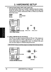
... slots or a primary audio/modem CNR on any of USB or CNR functions: J3-, J3+ and OC3. Three jumpers are used , reset these jumpers. H/W SETUP Motherboard Settings P4T-F P4T-F AUDIO Setting ADN 2 1 ENABLE AUDIO 3 2 DISABLE AUDIO 6) USB2 / CNRUSB Selection (J3-J3-/OC3) The CNR slot can support an optional USB hub CNR card... models only) The onboard Audio Codec may be enabled or disabled using a PCI audio card on a CNR slot (see CNR Slot later in this section). 3. P4T-F A7V266 CNR/USB Selection 12 J3J3+ 2 1 OC3 USB2 23 J3J3+ 3 2 OC3 CNRUSB 22...
... slots or a primary audio/modem CNR on any of USB or CNR functions: J3-, J3+ and OC3. Three jumpers are used , reset these jumpers. H/W SETUP Motherboard Settings P4T-F P4T-F AUDIO Setting ADN 2 1 ENABLE AUDIO 3 2 DISABLE AUDIO 6) USB2 / CNRUSB Selection (J3-J3-/OC3) The CNR slot can support an optional USB hub CNR card... models only) The onboard Audio Codec may be enabled or disabled using a PCI audio card on a CNR slot (see CNR Slot later in this section). 3. P4T-F A7V266 CNR/USB Selection 12 J3J3+ 2 1 OC3 USB2 23 J3J3+ 3 2 OC3 CNRUSB 22...

User Manual
Page 23
... RIMM) must be used to avoid breaking the signal lines, which are a serial connection in a Rambus interface, such as used in this motherboard. This assures the electrical integrity of channel A (RIMMA1 and RIMMA2) and channel B (RIMMB1 and RIMMB2) must be identical (see below). ...b. 128MB RDRAM RIMMB2 C-RIMM RIMMB1 128MB RDRAM C-RIMM RIMMA2 RIMMA1 c. 128MB RDRAM RIMMB2 128MB RDRAM RIMMB1 128MB RDRAM 128MB RDRAM RIMMA2 RIMMA1 ASUS P4T-F User's Manual 23 When C-RIMMs are required, it is recommended that are not populated by RDRAMs. A C-RIMM is necessary to complete ...
... RIMM) must be used to avoid breaking the signal lines, which are a serial connection in a Rambus interface, such as used in this motherboard. This assures the electrical integrity of channel A (RIMMA1 and RIMMA2) and channel B (RIMMB1 and RIMMB2) must be identical (see below). ...b. 128MB RDRAM RIMMB2 C-RIMM RIMMB1 128MB RDRAM C-RIMM RIMMA2 RIMMA1 c. 128MB RDRAM RIMMB2 128MB RDRAM RIMMB1 128MB RDRAM 128MB RDRAM RIMMA2 RIMMA1 ASUS P4T-F User's Manual 23 When C-RIMMs are required, it is recommended that are not populated by RDRAMs. A C-RIMM is necessary to complete ...
User Manual
Page 25
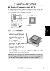
... into place. Then lift the lever upwards. Once completely inserted, press the CPU firmly and close the socket lever until it to prevent overheating. ASUS P4T-F User's Manual 25 The CPU that came with the correct orientation. Locate the P4 Socket 423 and open it by pulling the lever gently sideways... away from the socket. H/W SETUP CPU 3. Insert the CPU with the motherboard should drop easily into its alignment and look for the P4 Socket 423 CPU. 3. If the CPU does not fit, check its locked position.
... into place. Then lift the lever upwards. Once completely inserted, press the CPU firmly and close the socket lever until it to prevent overheating. ASUS P4T-F User's Manual 25 The CPU that came with the correct orientation. Locate the P4 Socket 423 and open it by pulling the lever gently sideways... away from the socket. H/W SETUP CPU 3. Insert the CPU with the motherboard should drop easily into its alignment and look for the P4 Socket 423 CPU. 3. If the CPU does not fit, check its locked position.


