User Manual
Page 2
... FOR INFORMATIONAL USE ONLY, AND ARE SUBJECT TO CHANGE AT ANY TIME WITHOUT NOTICE, AND SHOULD NOT BE CONSTRUED AS A COMMITMENT BY ASUS. Product Name: ASUS P4T-F Manual Revision: 1.01 E868 Release Date: September 2001 2 ASUS P4T-F User's Manual or (2) the serial number of Trend Micro, Inc. • Windows and MS-DOS are represented by...
... FOR INFORMATIONAL USE ONLY, AND ARE SUBJECT TO CHANGE AT ANY TIME WITHOUT NOTICE, AND SHOULD NOT BE CONSTRUED AS A COMMITMENT BY ASUS. Product Name: ASUS P4T-F Manual Revision: 1.01 E868 Release Date: September 2001 2 ASUS P4T-F User's Manual or (2) the serial number of Trend Micro, Inc. • Windows and MS-DOS are represented by...
User Manual
Page 3
...) Notebook (Tel): +886-2-2890-7122 (English) Desktop/Server (Tel):+886-2-2890-7123 (English) Fax: +886-2-2890-7698 Email: tsd@asus.com.tw WWW: www.asus.com.tw FTP: ftp.asus.com.tw/pub/ASUS ASUS COMPUTER INTERNATIONAL (America) Marketing Address: 6737 Mowry Avenue, Mowry Business Center, Building 2 Newark, CA 94560, USA Fax: +1-510-608-4555... Fax: +49-2102-9599-11 Support (Email): www.asuscom.de/de/support (for online support) WWW: www.asuscom.de FTP: ftp.asuscom.de/pub/ASUSCOM ASUS P4T-F User's Manual 3
...) Notebook (Tel): +886-2-2890-7122 (English) Desktop/Server (Tel):+886-2-2890-7123 (English) Fax: +886-2-2890-7698 Email: tsd@asus.com.tw WWW: www.asus.com.tw FTP: ftp.asus.com.tw/pub/ASUS ASUS COMPUTER INTERNATIONAL (America) Marketing Address: 6737 Mowry Avenue, Mowry Business Center, Building 2 Newark, CA 94560, USA Fax: +1-510-608-4555... Fax: +49-2102-9599-11 Support (Email): www.asuscom.de/de/support (for online support) WWW: www.asuscom.de FTP: ftp.asuscom.de/pub/ASUSCOM ASUS P4T-F User's Manual 3
User Manual
Page 4
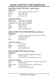
... 58 4.4.1 Chip Configuration 61 4.4.2 I/O Device Configuration 63 4.4.3 PCI Configuration 65 4.4.4 Shadow Configuration 67 4.5 Power Menu 68 4 ASUS P4T-F User's Manual FEATURES 8 2.1 The ASUS P4T-F 8 2.2 P4T-F Motherboard Components 12 3. INTRODUCTION 7 1.1 How This Manual Is Organized 7 1.2 Item Checklist 7 2. HARDWARE SETUP 14 3.1 P4T-F Motherboard Layout 14 3.2 Layout Contents 15 3.3 Hardware Setup Procedure 16 3.4 Motherboard Settings 17 3.5 System Memory 23...
... 58 4.4.1 Chip Configuration 61 4.4.2 I/O Device Configuration 63 4.4.3 PCI Configuration 65 4.4.4 Shadow Configuration 67 4.5 Power Menu 68 4 ASUS P4T-F User's Manual FEATURES 8 2.1 The ASUS P4T-F 8 2.2 P4T-F Motherboard Components 12 3. INTRODUCTION 7 1.1 How This Manual Is Organized 7 1.2 Item Checklist 7 2. HARDWARE SETUP 14 3.1 P4T-F Motherboard Layout 14 3.2 Layout Contents 15 3.3 Hardware Setup Procedure 16 3.4 Motherboard Settings 17 3.5 System Memory 23...
User Manual
Page 5
SOFTWARE REFERENCE 80 6.1 ASUS Live Update 80 6.2 ASUS PC Probe 81 6.3 CyberLink PowerPlayer SE 86 6.4 CyberLink VideoLive Mail 87 7. SOFTWARE SETUP 77 5.1 Install Operating System 77 5.2 Start Windows 77 5.3 P4T-F Motherboard Support CD 78 6. APPENDIX 89 7.1 Glossary 89 INDEX 95 ASUS P4T-F User's Manual 5 CONTENTS 4.5.1 Power Up Control 70 4.5.2 Hardware Monitor 71 4.6 Boot Menu 72 4.7 Exit Menu 74 5.
SOFTWARE REFERENCE 80 6.1 ASUS Live Update 80 6.2 ASUS PC Probe 81 6.3 CyberLink PowerPlayer SE 86 6.4 CyberLink VideoLive Mail 87 7. SOFTWARE SETUP 77 5.1 Install Operating System 77 5.2 Start Windows 77 5.3 P4T-F Motherboard Support CD 78 6. APPENDIX 89 7.1 Glossary 89 INDEX 95 ASUS P4T-F User's Manual 5 CONTENTS 4.5.1 Power Up Control 70 4.5.2 Hardware Monitor 71 4.6 Boot Menu 72 4.7 Exit Menu 74 5.
User Manual
Page 6
... the Federal Register, National Archives and Records Administration, U.S. Cet appareil numérique de la classe B est conforme à la norme NMB-003 du Canada. 6 ASUS P4T-F User's Manual Operation is subject to the following measures: • Re-orient or relocate the receiving antenna. • Increase the separation between the equipment and...
... the Federal Register, National Archives and Records Administration, U.S. Cet appareil numérique de la classe B est conforme à la norme NMB-003 du Canada. 6 ASUS P4T-F User's Manual Operation is subject to the following measures: • Re-orient or relocate the receiving antenna. • Increase the separation between the equipment and...
User Manual
Page 7
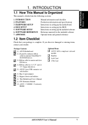
... Intructions on setting up the motherboard. INTRODUCTION Manual / Checklist 1. BIOS SETUP 5. FEATURES 3. INTRODUCTION 2. Package Contents (1) ASUS Motherboard (1) 40-pin 80-conductor ribbon cable for internal UltraDMA33/ 66/100 IDE drives (1) Ribbon cable for master and ... disk drives (1) ASUS 2-port USB connector set with bracket (1) Bag of spare jumpers (1) Support drivers and utilities (1) This Motherboard User's Manual (1) CPU Retention Module (2) ASUS C-RIMM Continuity RIMM Optional Items ASUS IrDA-compliant infrared module Rambus LAN Card 1394 Card ASUS P4T-F User's Manual...
... Intructions on setting up the motherboard. INTRODUCTION Manual / Checklist 1. BIOS SETUP 5. FEATURES 3. INTRODUCTION 2. Package Contents (1) ASUS Motherboard (1) 40-pin 80-conductor ribbon cable for internal UltraDMA33/ 66/100 IDE drives (1) Ribbon cable for master and ... disk drives (1) ASUS 2-port USB connector set with bracket (1) Bag of spare jumpers (1) Support drivers and utilities (1) This Motherboard User's Manual (1) CPU Retention Module (2) ASUS C-RIMM Continuity RIMM Optional Items ASUS IrDA-compliant infrared module Rambus LAN Card 1394 Card ASUS P4T-F User's Manual...

User Manual
Page 8
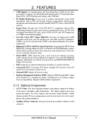
... to meet the increase in 64, 96, 128, 192, 256, 512MB) up to 100MB/ sec; FEATURES 2.1 The ASUS P4T-F The ASUS P4T-F motherboard is enabled. • Easy-to-Use DIP Switches: As an alternative to JumperFree Mode™, jumpers and DSW ...RDRAMs are included to 2GB. The slot is keyed to support only the latest 1.5 volt AGP cards: i.e.: ASUS V3800 and newer versions. • JumperFree™ Mode: Now processor settings and easy overclocking of frequency and Vcore...• AGP Pro Slot: Comes with support for exceptiona peripheral connectivity options. 8 ASUS P4T-F User's Manual 2.
... to meet the increase in 64, 96, 128, 192, 256, 512MB) up to 100MB/ sec; FEATURES 2.1 The ASUS P4T-F The ASUS P4T-F motherboard is enabled. • Easy-to-Use DIP Switches: As an alternative to JumperFree Mode™, jumpers and DSW ...RDRAMs are included to 2GB. The slot is keyed to support only the latest 1.5 volt AGP cards: i.e.: ASUS V3800 and newer versions. • JumperFree™ Mode: Now processor settings and easy overclocking of frequency and Vcore...• AGP Pro Slot: Comes with support for exceptiona peripheral connectivity options. 8 ASUS P4T-F User's Manual 2.
User Manual
Page 9
...PCI allows multiple PCI transfers from COM2 to four analog line inputs, two stereo outputs, and one parallel port with this 6 tooth connector. ASUS P4T-F User's Manual 9 UART2 can support Bus Master PCI cards, such as CPU and systerm voltages, temperatures, and fan status through BIOS, which.... • Onboard LED: Signals AC power is okay. • Desktop Management Interface (DMI): Supports DMI through the onboard hardware and the bundled ASUS PC Probe or Intel LDCM software. • Legacy Free: Provides five 32-bit PCI (PCI 2.2 compliant) with no ISA, eliminating bottlenecks and...
...PCI allows multiple PCI transfers from COM2 to four analog line inputs, two stereo outputs, and one parallel port with this 6 tooth connector. ASUS P4T-F User's Manual 9 UART2 can support Bus Master PCI cards, such as CPU and systerm voltages, temperatures, and fan status through BIOS, which.... • Onboard LED: Signals AC power is okay. • Desktop Management Interface (DMI): Supports DMI through the onboard hardware and the bundled ASUS PC Probe or Intel LDCM software. • Legacy Free: Provides five 32-bit PCI (PCI 2.2 compliant) with no ISA, eliminating bottlenecks and...
User Manual
Page 10
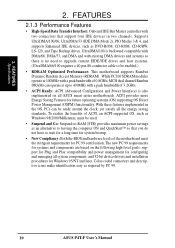
...also implemented on the following high-level goals: support for Plug and Play compatibility and power management for configuring and managing all ASUS smart series motherboards. FEATURES Specifications 2. With these features implemented in two channels. The new PC 99 requirements for PC 99 ...66, UltraDMA/33 (IDE DMA Mode 2), PIO Modes 3 & 4, and supports Enhanced IDE devices, such as required by PC 99. 10 ASUS P4T-F User's Manual FEATURES 2.1.3 Performance Features • High-Speed Data Transfer Interface: Onboard IDE Bus Master controller with two connectors that you do not...
...also implemented on the following high-level goals: support for Plug and Play compatibility and power management for configuring and managing all ASUS smart series motherboards. FEATURES Specifications 2. With these features implemented in two channels. The new PC 99 requirements for PC 99 ...66, UltraDMA/33 (IDE DMA Mode 2), PIO Modes 3 & 4, and supports Enhanced IDE devices, such as required by PC 99. 10 ASUS P4T-F User's Manual FEATURES 2.1.3 Performance Features • High-Speed Data Transfer Interface: Onboard IDE Bus Master controller with two connectors that you do not...
User Manual
Page 11
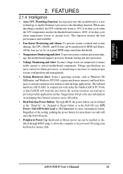
...of its duty cycle when temperature lowers to present enormous user interfaces and run large applications. The onboard hardware ASUS ASIC in 3.8 Connectors for more critical for future processors, so monitoring is enabled, the CPU with either the bundled...system damage, the CPU, MAIN, and PCI fans can be enabled or disabled through BIOS setup to allow the computer to critical motherboard components. ASUS P4T-F User's Manual 11 2. FEATURES 2.1.4 Intelligence • Auto CPU Throttling Function: Incorporated into this motherboard supports processor thermal sensing and auto-protection....
...of its duty cycle when temperature lowers to present enormous user interfaces and run large applications. The onboard hardware ASUS ASIC in 3.8 Connectors for more critical for future processors, so monitoring is enabled, the CPU with either the bundled...system damage, the CPU, MAIN, and PCI fans can be enabled or disabled through BIOS setup to allow the computer to critical motherboard components. ASUS P4T-F User's Manual 11 2. FEATURES 2.1.4 Intelligence • Auto CPU Throttling Function: Incorporated into this motherboard supports processor thermal sensing and auto-protection....
User Manual
Page 12
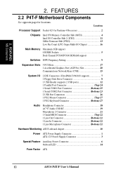
FEATURES 2.2 P4T-F Motherboard Components See opposite page for Pentium 4 Processors 2 Chipsets Intel 850 Memory Controller Hub (MCH 4 Intel I/O Controller Hub 2 (ICH2 11 2Mbit Firmware Hub (FWH 13... 22 1 Line In Connector Bottom) 22 1 Line Microphone Connector Bottom) 22 Hardware Monitoring ASUS onboard chipset 10 Power ATX Power Supply Connector 1 ATX 12V Power Supply Connector 3 Special Feature Auxillary Power Connector 6 Onboard LED 14 Form Factor ATX 12 ASUS P4T-F User's Manual Location Processor Support Socket 423 for locations. 2. FEATURES MB Components 2.
FEATURES 2.2 P4T-F Motherboard Components See opposite page for Pentium 4 Processors 2 Chipsets Intel 850 Memory Controller Hub (MCH 4 Intel I/O Controller Hub 2 (ICH2 11 2Mbit Firmware Hub (FWH 13... 22 1 Line In Connector Bottom) 22 1 Line Microphone Connector Bottom) 22 Hardware Monitoring ASUS onboard chipset 10 Power ATX Power Supply Connector 1 ATX 12V Power Supply Connector 3 Special Feature Auxillary Power Connector 6 Onboard LED 14 Form Factor ATX 12 ASUS P4T-F User's Manual Location Processor Support Socket 423 for locations. 2. FEATURES MB Components 2.
User Manual
Page 14
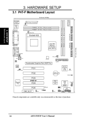
H/W SETUP Motherboard Layout 30.5cm (12.0in) AUX Power Connector 3. HARDWARE SETUP 3.1 P4T-F Motherboard Layout PS/2KBMS T: Mouse B: Keyboard USB T: Port1 B: Port2 COM1 24.4cm (9.60in) ATX Power Connector USBPWR RIMMB2 (16/18 bit, 184-pin module) ...Audio Codec HEADPHONE PCI1 PCI2 CR2032 3V Lithium Cell CMOS Power Intel I/O Controller Hub (ICH2) CLRTC HDDLED Super I/O PCI3 P4T-F PCI4 PCI5 LED CNR_SLOT IR ADN 2Mbit Firmware Hub J3J3+ USB2 ASUS ASIC with Hardware Monitor PCI_FAN JEN DIP Switches OC3 CHASSIS PANEL Grayed components are available only on certain models at...
H/W SETUP Motherboard Layout 30.5cm (12.0in) AUX Power Connector 3. HARDWARE SETUP 3.1 P4T-F Motherboard Layout PS/2KBMS T: Mouse B: Keyboard USB T: Port1 B: Port2 COM1 24.4cm (9.60in) ATX Power Connector USBPWR RIMMB2 (16/18 bit, 184-pin module) ...Audio Codec HEADPHONE PCI1 PCI2 CR2032 3V Lithium Cell CMOS Power Intel I/O Controller Hub (ICH2) CLRTC HDDLED Super I/O PCI3 P4T-F PCI4 PCI5 LED CNR_SLOT IR ADN 2Mbit Firmware Hub J3J3+ USB2 ASUS ASIC with Hardware Monitor PCI_FAN JEN DIP Switches OC3 CHASSIS PANEL Grayed components are available only on certain models at...
User Manual
Page 15
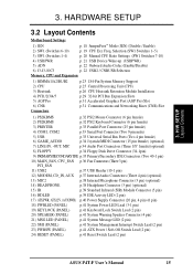
... System Management Interrupt Switch Lead (2 pin) 23) PWRSW (PANEL) p.41 ATX Power / Soft-Off Switch Lead (2 pin) 24) RESET (PANEL) p.41 Reset Switch Lead (2 pin) ASUS P4T-F User's Manual 15 HARDWARE SETUP 3.2 Layout Contents Motherboard Settings 1) JEN p. 18 JumperFree™ Mode (JEN) (Disable / Enable) 2) SW1 (Switches 6-10) p. 19 CPU Ext.
... System Management Interrupt Switch Lead (2 pin) 23) PWRSW (PANEL) p.41 ATX Power / Soft-Off Switch Lead (2 pin) 24) RESET (PANEL) p.41 Reset Switch Lead (2 pin) ASUS P4T-F User's Manual 15 HARDWARE SETUP 3.2 Layout Contents Motherboard Settings 1) JEN p. 18 JumperFree™ Mode (JEN) (Disable / Enable) 2) SW1 (Switches 6-10) p. 19 CPU Ext.
User Manual
Page 16
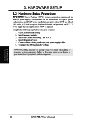
.... Complete the following steps before using your motherboard, peripherals, and/or components. 3. Install memory modules 3. Install the Central Processing Unit (CPU) 4. H/W SETUP Getting Started 16 ASUS P4T-F User's Manual For typical system configurations, an ATX12V power supply that can supply at least 8.5A on the +12V lead is recommended for this motherboard...
.... Complete the following steps before using your motherboard, peripherals, and/or components. 3. Install memory modules 3. Install the Central Processing Unit (CPU) 4. H/W SETUP Getting Started 16 ASUS P4T-F User's Manual For typical system configurations, an ATX12V power supply that can supply at least 8.5A on the +12V lead is recommended for this motherboard...

User Manual
Page 17
Use a grounded wrist strap before you work on the inside. 2. P4T-F P4T-F Onboard LED ON Standby Power OFF Powered Off 3. To protect them against damage from the system. 5. 3. Computer motherboards and expansion cards contain very delicate Integrated... in or remove the ATX power connector on the bag that the ATX power supply is switched off before handling computer components. H/W SETUP Motherboard Settings ASUS P4T-F User's Manual 17 Hold components by the edges and try not to a metal object, such as the power supply case. 3. HARDWARE SETUP 3.4 Motherboard Settings This...
Use a grounded wrist strap before you work on the inside. 2. P4T-F P4T-F Onboard LED ON Standby Power OFF Powered Off 3. To protect them against damage from the system. 5. 3. Computer motherboards and expansion cards contain very delicate Integrated... in or remove the ATX power connector on the bag that the ATX power supply is switched off before handling computer components. H/W SETUP Motherboard Settings ASUS P4T-F User's Manual 17 Hold components by the edges and try not to a metal object, such as the power supply case. 3. HARDWARE SETUP 3.4 Motherboard Settings This...
User Manual
Page 18
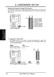
...Disable (Jumper Mode) [1-2] JEN OFF SW1 ON 1 2 3 4 5 6 7 8 9 10 P4T-F 12 Jumper Mode P4T-F JumperFree™ Mode Setting 23 Jumper Free (Default) 18 ASUS P4T-F User's Manual Frequency Selection 7. Frequency Selection 9. The JumperFree™ mode allows processor settings to enable... Motherboard Settings 1) JumperFree™ Mode (JEN) This jumper allows you to be made through the DIP switches. Frequency Multiple 2. Frequency Multiple 5. P4T-F P4T-F DIP Switches ON 1 2 3 4 5 6 7 8 9 10 ON OFF SW1 1. Frequency Selection 8. Frequency Selection 10. HARDWARE SETUP...
...Disable (Jumper Mode) [1-2] JEN OFF SW1 ON 1 2 3 4 5 6 7 8 9 10 P4T-F 12 Jumper Mode P4T-F JumperFree™ Mode Setting 23 Jumper Free (Default) 18 ASUS P4T-F User's Manual Frequency Selection 7. Frequency Selection 9. The JumperFree™ mode allows processor settings to enable... Motherboard Settings 1) JumperFree™ Mode (JEN) This jumper allows you to be made through the DIP switches. Frequency Multiple 2. Frequency Multiple 5. P4T-F P4T-F DIP Switches ON 1 2 3 4 5 6 7 8 9 10 ON OFF SW1 1. Frequency Selection 8. Frequency Selection 10. HARDWARE SETUP...
User Manual
Page 19
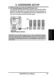
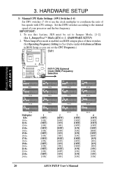
SW1 P4T-F P4T-F CPU External Frequency Selection CPU 100.0MHz 103.0MHz 105.0MHz 110.0MHz AGP 66.0MHz 68.0MHz 70.0MHz 73.0MHz PCI 33.0MHz ... PCI bus. Overclocking the processor is not recommended. The BUS Clock multiplied by the Frequency Multiple equals the CPU's Internal frequency (the advertised CPU speed). ASUS P4T-F User's Manual 19 H/W SETUP Motherboard Settings 3. HARDWARE SETUP 2) CPU External Frequency Selection (SW1 Switches 6-10) This option tells the clock generator what frequency to send...
SW1 P4T-F P4T-F CPU External Frequency Selection CPU 100.0MHz 103.0MHz 105.0MHz 110.0MHz AGP 66.0MHz 68.0MHz 70.0MHz 73.0MHz PCI 33.0MHz ... PCI bus. Overclocking the processor is not recommended. The BUS Clock multiplied by the Frequency Multiple equals the CPU's Internal frequency (the advertised CPU speed). ASUS P4T-F User's Manual 19 H/W SETUP Motherboard Settings 3. HARDWARE SETUP 2) CPU External Frequency Selection (SW1 Switches 6-10) This option tells the clock generator what frequency to send...
User Manual
Page 20
Set the DSW switches according to User Define under 4.4 Advanced Menu in 3, HARDWARE SETUP.) 2. H/W SETUP Motherboard Settings P4T-F CPU External Clock (BUS) Frequency P4T-F Selection ON ON ON ON 1 2 3 4 5 6 7 8 9 10 8.0x ON 1 2 3 4 5 6 7 8 9 10 13.0x ON 1 2 3 4 5 6 7 8 9 10 17.0x ON 1 2 3 4 5 6 7 8 9 10 21.0x ON 1 2 3...OFF] [OFF] [OFF] [OFF] [OFF] [OFF] [OFF] [ON] [ON] [ON] [ON] [ON] [ON] [ON] [ON] 20 ASUS P4T-F User's Manual IMPORTANT: 1. When JumperFree mode is enabled, use BIOS setup in place of these switches. (Set Operating Frequency Setting to the internal speed of...
Set the DSW switches according to User Define under 4.4 Advanced Menu in 3, HARDWARE SETUP.) 2. H/W SETUP Motherboard Settings P4T-F CPU External Clock (BUS) Frequency P4T-F Selection ON ON ON ON 1 2 3 4 5 6 7 8 9 10 8.0x ON 1 2 3 4 5 6 7 8 9 10 13.0x ON 1 2 3 4 5 6 7 8 9 10 17.0x ON 1 2 3 4 5 6 7 8 9 10 21.0x ON 1 2 3...OFF] [OFF] [OFF] [OFF] [OFF] [OFF] [OFF] [ON] [ON] [ON] [ON] [ON] [ON] [ON] [ON] 20 ASUS P4T-F User's Manual IMPORTANT: 1. When JumperFree mode is enabled, use BIOS setup in place of these switches. (Set Operating Frequency Setting to the internal speed of...
User Manual
Page 21
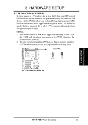
... NOT exceed the power supply capability (+5VSB) whether under normal working conditions or in low power mode) using the connected USB devices. USBPWR 2 1 +5VSB 3 2 +5V P4T-F P4T-F USB Device Wake Up 3. HARDWARE SETUP 4) USB Device Wake-up (USBPWR) Set these jumpers are set to allow wake up . 2. system running in sleep mode... 2A on the +5VSB lead when these jumpers to +5V to allow wake up from the S1 sleep state (CPU stopped; NOTES: 1. H/W SETUP Motherboard Settings ASUS P4T-F User's Manual 21 RAM in reduced power mode). 3. RAM refreshed;
... NOT exceed the power supply capability (+5VSB) whether under normal working conditions or in low power mode) using the connected USB devices. USBPWR 2 1 +5VSB 3 2 +5V P4T-F P4T-F USB Device Wake Up 3. HARDWARE SETUP 4) USB Device Wake-up (USBPWR) Set these jumpers are set to allow wake up . 2. system running in sleep mode... 2A on the +5VSB lead when these jumpers to +5V to allow wake up from the S1 sleep state (CPU stopped; NOTES: 1. H/W SETUP Motherboard Settings ASUS P4T-F User's Manual 21 RAM in reduced power mode). 3. RAM refreshed;
User Manual
Page 22
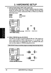
H/W SETUP Motherboard Settings P4T-F P4T-F AUDIO Setting ADN 2 1 ENABLE AUDIO 3 2 DISABLE AUDIO 6) USB2 / CNRUSB Selection (J3-J3-/OC3) The CNR slot can support an optional USB hub CNR card. Disable ... of the expansion slots or a primary audio/modem CNR on a CNR slot (see CNR Slot later in this section). P4T-F A7V266 CNR/USB Selection 12 J3J3+ 2 1 OC3 USB2 23 J3J3+ 3 2 OC3 CNRUSB 22 ASUS P4T-F User's Manual HARDWARE SETUP 5) Onboard Audio Setting (ADN) (audio models only) The onboard Audio Codec may be enabled...
H/W SETUP Motherboard Settings P4T-F P4T-F AUDIO Setting ADN 2 1 ENABLE AUDIO 3 2 DISABLE AUDIO 6) USB2 / CNRUSB Selection (J3-J3-/OC3) The CNR slot can support an optional USB hub CNR card. Disable ... of the expansion slots or a primary audio/modem CNR on a CNR slot (see CNR Slot later in this section). P4T-F A7V266 CNR/USB Selection 12 J3J3+ 2 1 OC3 USB2 23 J3J3+ 3 2 OC3 CNRUSB 22 ASUS P4T-F User's Manual HARDWARE SETUP 5) Onboard Audio Setting (ADN) (audio models only) The onboard Audio Codec may be enabled...


