Asus P4SP MX SE
Related Manual Pages


Related Videos

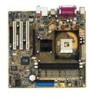
Motherboard Asus P4SP-MX SE
Duration: :35
Total Views: 388
Duration: :35
Total Views: 388
Similar Questions

M2n Mx Se Motherboard Support Windows 10 ?
M2N MX SE motherboard support windows 10 ?
M2N MX SE motherboard support windows 10 ?
(Posted by mrvijay6335 10 months ago)

Jumper Settig Asus P5ld2-vm Se
please send jumper setting asus p5ld2-vm se
please send jumper setting asus p5ld2-vm se
(Posted by sabersal 10 years ago)

Would Any New Geforce Graphics Cards Fit Into My Old Asus P5ld2-vm Se Motherbord
fit into my old asus p5ld2-vm se motherbord?
fit into my old asus p5ld2-vm se motherbord?
(Posted by mornevolschenk 11 years ago)