P4SGL-VM User Manual
Page 8
How this guide This user guide contains the information you need when installing the ASUS P4SGL-VM motherboard. Detailed descriptions of the BIOS parameters are also provided. • Chapter 5: Software support This chapter describes the contents of ... document. About this guide is organized This manual contains the following parts: • Chapter 1: Product introduction This chapter describes the features of the P4SGL-VM motherboard. viii It includes brief descriptions of the special attributes of the switches, jumpers, and connectors on the motherboard. • Chapter 3: Powering...
How this guide This user guide contains the information you need when installing the ASUS P4SGL-VM motherboard. Detailed descriptions of the BIOS parameters are also provided. • Chapter 5: Software support This chapter describes the contents of ... document. About this guide is organized This manual contains the following parts: • Chapter 1: Product introduction This chapter describes the features of the P4SGL-VM motherboard. viii It includes brief descriptions of the special attributes of the switches, jumpers, and connectors on the motherboard. • Chapter 3: Powering...

P4SGL-VM User Manual
Page 12
ASUS P4SGL-VM motherboard
ASUS P4SGL-VM motherboard
P4SGL-VM User Manual
Page 13
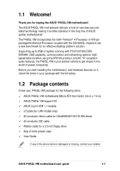
...4 Processor in 478-pin package/Northwood Processor coupled with the list below. 1.2 Package contents Check your P4SGL-VM package for the following items. ASUS P4SGL-VM motherboard (Micro-ATX form factor: 9.6-in x 7.5-in the long line of system memory with PC2100/... new benchmark for buying the ASUS® P4SGL-VM motherboard! ASUS P4SGL-VM motherboard user guide 1-1 Supporting up to 2GB of ASUS quality motherboards! 1.1 Welcome! Thank you start installing the motherboard, and hardware devices on it another standout in ) ASUS P4SGL-VM support CD ASUS 2-port USB 1.1 module I/O...
...4 Processor in 478-pin package/Northwood Processor coupled with the list below. 1.2 Package contents Check your P4SGL-VM package for the following items. ASUS P4SGL-VM motherboard (Micro-ATX form factor: 9.6-in x 7.5-in the long line of system memory with PC2100/... new benchmark for buying the ASUS® P4SGL-VM motherboard! ASUS P4SGL-VM motherboard user guide 1-1 Supporting up to 2GB of ASUS quality motherboards! 1.1 Welcome! Thank you start installing the motherboard, and hardware devices on it another standout in ) ASUS P4SGL-VM support CD ASUS 2-port USB 1.1 module I/O...
P4SGL-VM User Manual
Page 15
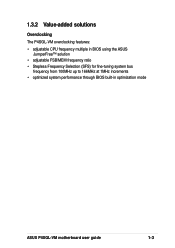
1.3.2 Value-added solutions Overclocking The P4SGL-VM overclocking features: • adjustable CPU frequency multiple in BIOS using the ASUS JumperFree™ solution • adjustable FSB/MEM frequency ratio • Stepless Frequency Selection (SFS) for fine-tuning system bus frequency from 100MHz up to 166MHz at 1MHz increments • optimized system performance through BIOS built-in optimization mode ASUS P4SGL-VM motherboard user guide 1-3
1.3.2 Value-added solutions Overclocking The P4SGL-VM overclocking features: • adjustable CPU frequency multiple in BIOS using the ASUS JumperFree™ solution • adjustable FSB/MEM frequency ratio • Stepless Frequency Selection (SFS) for fine-tuning system bus frequency from 100MHz up to 166MHz at 1MHz increments • optimized system performance through BIOS built-in optimization mode ASUS P4SGL-VM motherboard user guide 1-3

P4SGL-VM User Manual
Page 17
1 23 4 5 15 14 13 12 11 16 17 10 18 9 8 76 19 26 25 24 23 22 21 20 ASUS P4SGL-VM motherboard user guide 1-5
1 23 4 5 15 14 13 12 11 16 17 10 18 9 8 76 19 26 25 24 23 22 21 20 ASUS P4SGL-VM motherboard user guide 1-5
P4SGL-VM User Manual
Page 19
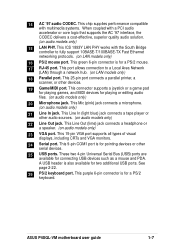
... pointing devices or other serial devices. 25 USB ports. This purple 6-pin connector is for a PS/2 keyboard. A USB header is for two additional USB ports. ASUS P4SGL-VM motherboard user guide 1-7 14 AC '97 audio CODEC. This chip supplies performance compatible with multimedia systems. When coupled with the South Bridge controller to a Local...
... pointing devices or other serial devices. 25 USB ports. This purple 6-pin connector is for a PS/2 keyboard. A USB header is for two additional USB ports. ASUS P4SGL-VM motherboard user guide 1-7 14 AC '97 audio CODEC. This chip supplies performance compatible with multimedia systems. When coupled with the South Bridge controller to a Local...

P4SGL-VM User Manual
Page 22
ASUS P4SGL-VM motherboard
ASUS P4SGL-VM motherboard

P4SGL-VM User Manual
Page 23
... MicroATX form factor that measures 9.6 inches x 7.5 inches, a standard fit for most chassis. Do not overtighten the screws! Failure to the rear part of the chassis ASUS P4SGL-VM motherboard user guide 2-1 Doing so may cause you physical injury and damage motherboard components. 2.1.1 Placement direction When installing the motherboard, make sure that you install...
... MicroATX form factor that measures 9.6 inches x 7.5 inches, a standard fit for most chassis. Do not overtighten the screws! Failure to the rear part of the chassis ASUS P4SGL-VM motherboard user guide 2-1 Doing so may cause you physical injury and damage motherboard components. 2.1.1 Placement direction When installing the motherboard, make sure that you install...
P4SGL-VM User Manual
Page 25
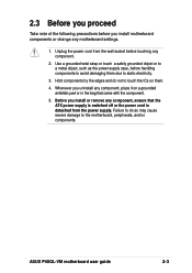
... detached from the wall socket before touching any component. 2. Failure to do not to avoid damaging them . 4. Unplug the power cord from the power supply. ASUS P4SGL-VM motherboard user guide 2-3 2.3 Before you proceed Take note of the following precautions before you install or remove any component, ensure that came with the component. 5.
... detached from the wall socket before touching any component. 2. Failure to do not to avoid damaging them . 4. Unplug the power cord from the power supply. ASUS P4SGL-VM motherboard user guide 2-3 2.3 Before you proceed Take note of the following precautions before you install or remove any component, ensure that came with the component. 5.

P4SGL-VM User Manual
Page 27
Locate the 478-pin ZIF socket on the motherboard. 2. Socket Lever 90 - 100 Make sure that the socket lever is lifted up to a 90°-100° angle. ASUS P4SGL-VM motherboard user guide 2-5 Unlock the socket by pressing the lever sideways, then lift it up to install a CPU. 1. 2.4.2 Installing the CPU Follow these steps to 90°-100° angle, otherwise the CPU does not fit in completely.
Locate the 478-pin ZIF socket on the motherboard. 2. Socket Lever 90 - 100 Make sure that the socket lever is lifted up to a 90°-100° angle. ASUS P4SGL-VM motherboard user guide 2-5 Unlock the socket by pressing the lever sideways, then lift it up to install a CPU. 1. 2.4.2 Installing the CPU Follow these steps to 90°-100° angle, otherwise the CPU does not fit in completely.

P4SGL-VM User Manual
Page 29
... a boxed Intel Pentium 4 478/Northwood Processor, the package includes the heatsink, fan, and retention mechanism. In case you use only Intel certified heatsink and fan. ASUS P4SGL-VM motherboard user guide 2-7 2.4.3 Installing the heatsink and fan The Intel® Pentium® 4 478/Northwood Processor requires a specially designed heatsink and fan assembly to install...
... a boxed Intel Pentium 4 478/Northwood Processor, the package includes the heatsink, fan, and retention mechanism. In case you use only Intel certified heatsink and fan. ASUS P4SGL-VM motherboard user guide 2-7 2.4.3 Installing the heatsink and fan The Intel® Pentium® 4 478/Northwood Processor requires a specially designed heatsink and fan assembly to install...

P4SGL-VM User Manual
Page 31
CPU Fan Connector (CPUFAN1) Don't forget to plug this connector. Hardware monitoring errors may occur if you fail to connect the CPU fan connector! When secure, the retention locks should point to opposite directions. 2.4.4 Connecting the CPU fan cable When the fan, heatsink, and the retention mechanism are in place, connect the CPU fan cable to the connector on the retention mechanism to secure the heatsink and fan to the module base. ASUS P4SGL-VM motherboard user guide 2-9 3. Push down the locks on the motherboard labeled CPUFAN1.
CPU Fan Connector (CPUFAN1) Don't forget to plug this connector. Hardware monitoring errors may occur if you fail to connect the CPU fan connector! When secure, the retention locks should point to opposite directions. 2.4.4 Connecting the CPU fan cable When the fan, heatsink, and the retention mechanism are in place, connect the CPU fan cable to the connector on the retention mechanism to secure the heatsink and fan to the module base. ASUS P4SGL-VM motherboard user guide 2-9 3. Push down the locks on the motherboard labeled CPUFAN1.

P4SGL-VM User Manual
Page 33
2.5.2 Memory configurations You may install any DDR DIMMs with 64MB, 128MB, 256MB, 512MB, and 1GB densities into the two DIMM sockets. Use the following combinations to install DDR DIMMs. DIMM Location 184-pin DDR DIMM Total Memory Socket 1 (Rows 0&1) 64MB, 128MB, 256MB, 512MB, 1GB x1 = Socket 2 (Rows 2&3) 64MB, 128MB, 256MB, 512MB, 1GB x1 = Total system memory (Max. 2GB) = ASUS P4SGL-VM motherboard user guide 2-11
2.5.2 Memory configurations You may install any DDR DIMMs with 64MB, 128MB, 256MB, 512MB, and 1GB densities into the two DIMM sockets. Use the following combinations to install DDR DIMMs. DIMM Location 184-pin DDR DIMM Total Memory Socket 1 (Rows 0&1) 64MB, 128MB, 256MB, 512MB, 1GB x1 = Socket 2 (Rows 2&3) 64MB, 128MB, 256MB, 512MB, 1GB x1 = Total system memory (Max. 2GB) = ASUS P4SGL-VM motherboard user guide 2-11

P4SGL-VM User Manual
Page 35
Support the DIMM lightly with extra force. 2. Remove the DIMM from the socket. The DIMM might get damaged when it flips out with your fingers when pressing the retaining clips. ASUS P4SGL-VM motherboard user guide 2-13 2.5.4 Removing a DIMM Follow these steps to unlock the DIMM. Simultaneously press the retaining clips outward to remove a DIMM. 1.
Support the DIMM lightly with extra force. 2. Remove the DIMM from the socket. The DIMM might get damaged when it flips out with your fingers when pressing the retaining clips. ASUS P4SGL-VM motherboard user guide 2-13 2.5.4 Removing a DIMM Follow these steps to unlock the DIMM. Simultaneously press the retaining clips outward to remove a DIMM. 1.
P4SGL-VM User Manual
Page 37
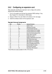
.../2 Compatible Mouse Port 13 8 Numeric Data Processor 14* 9 Primary IDE Channel 15* 10 Secondary IDE Channel *These IRQs are usually available for the expansion card. ASUS P4SGL-VM motherboard user guide 2-15 Turn on BIOS setup. 2. See Chapter 4 for information on the system and change the necessary BIOS settings, if any.
.../2 Compatible Mouse Port 13 8 Numeric Data Processor 14* 9 Primary IDE Channel 15* 10 Secondary IDE Channel *These IRQs are usually available for the expansion card. ASUS P4SGL-VM motherboard user guide 2-15 Turn on BIOS setup. 2. See Chapter 4 for information on the system and change the necessary BIOS settings, if any.
P4SGL-VM User Manual
Page 39
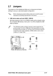
... can provide at least 1A on the motherboard allow you to change some feature settings to wake up feature. P4SGL-VM ® P4SGL-VM USB Device Wake Up USBV1 3 2 2 1 +5V (Default) +5VSB USBV2 2 1 +5V (Default) 3 2 +5VSB ASUS P4SGL-VM motherboard user guide 2-17 The USB device wake-up . USB device wake-up (3-pin USBV1, USBV2) Set these...
... can provide at least 1A on the motherboard allow you to change some feature settings to wake up feature. P4SGL-VM ® P4SGL-VM USB Device Wake Up USBV1 3 2 2 1 +5V (Default) +5VSB USBV2 2 1 +5V (Default) 3 2 +5VSB ASUS P4SGL-VM motherboard user guide 2-17 The USB device wake-up . USB device wake-up (3-pin USBV1, USBV2) Set these...

P4SGL-VM User Manual
Page 41
... pins will cause damage to the power connector on hard drives and CD-ROM drives, but may be on the opposite side on the connectors. P4SGL-VM ® TIP: If the case-mounted LED does not light, try reversing the 2-pin plug. Pin 1 is usually on the motherboard. 2.8 Connectors This ... on the side closest to your motherboard. Hard disk activity LED (2-pin IDELED) This connector supplies power to the hard disk activity LED. IDELED P4SGL-VM IDE Activity LED ASUS P4SGL-VM motherboard user guide 2-19 Some pins are clearly distinguished from jumpers in the Motherboard Layout.
... pins will cause damage to the power connector on hard drives and CD-ROM drives, but may be on the opposite side on the connectors. P4SGL-VM ® TIP: If the case-mounted LED does not light, try reversing the 2-pin plug. Pin 1 is usually on the motherboard. 2.8 Connectors This ... on the side closest to your motherboard. Hard disk activity LED (2-pin IDELED) This connector supplies power to the hard disk activity LED. IDELED P4SGL-VM IDE Activity LED ASUS P4SGL-VM motherboard user guide 2-19 Some pins are clearly distinguished from jumpers in the Motherboard Layout.

P4SGL-VM User Manual
Page 43
... sinks instead of the expansion slots. The fan wiring and plug may damage the motherboard components. CHASFAN1 P4SGL-VM GND +12V Rotation CPUFAN1 GND +12V Rotation SPSFAN1 ® GND +12V NC P4SGL-VM 12-Volt Cooling Fan Power ASUS P4SGL-VM motherboard user guide 2-21 Floppy disk drive connector (34-1 pin FLOPPY) This connector supports the provided...
... sinks instead of the expansion slots. The fan wiring and plug may damage the motherboard components. CHASFAN1 P4SGL-VM GND +12V Rotation CPUFAN1 GND +12V Rotation SPSFAN1 ® GND +12V NC P4SGL-VM 12-Volt Cooling Fan Power ASUS P4SGL-VM motherboard user guide 2-21 Floppy disk drive connector (34-1 pin FLOPPY) This connector supports the provided...

P4SGL-VM User Manual
Page 45
...on audio models only) These connectors allow you do not connect the Intel front panel audio cable. ASUS P4SGL-VM motherboard user guide 2-23 P4SGL-VM ® FPAUDIO1 LOUT_L NC LOUT_R MICPWR MIC2 2 10 1 9 BOUT_L BOUT_R +5VA AGND_A P4SGL-VM Intel Panel Connector Make sure to place jumper caps over pins 1-2 and 5-6 if you to ...are shorted. It also allows the sharing of mono_in (such as a phone) and a mono_out (such as a CD-ROM, TV tuner, or MPEG card. P4SGL-VM ® MODEM Modem-Out Ground Ground Modem-In CD (Black) AUX (White) Left Audio Channel Ground Ground Right Audio Channel...
...on audio models only) These connectors allow you do not connect the Intel front panel audio cable. ASUS P4SGL-VM motherboard user guide 2-23 P4SGL-VM ® FPAUDIO1 LOUT_L NC LOUT_R MICPWR MIC2 2 10 1 9 BOUT_L BOUT_R +5VA AGND_A P4SGL-VM Intel Panel Connector Make sure to place jumper caps over pins 1-2 and 5-6 if you to ...are shorted. It also allows the sharing of mono_in (such as a phone) and a mono_out (such as a CD-ROM, TV tuner, or MPEG card. P4SGL-VM ® MODEM Modem-Out Ground Ground Modem-In CD (Black) AUX (White) Left Audio Channel Ground Ground Right Audio Channel...

P4SGL-VM User Manual
Page 47
.... Infrared module connector (5-1 pin IR1) This connector supports an optional wireless transmitting and receiving infrared module. P4SGL-VM SIRQ1 ® SERIRQ GND P4SGL-VM SIRQ1 Connector ASUS P4SGL-VM motherboard user guide 2-25 Configure the UART2 Use As parameter in BIOS to the pin definitions. (An ... as those with PCMCIA function. You must also configure the UART2 Use As parameter in the package.) P4SGL-VM IR1 Front View Back View IRTX GND IRRX +5V ® 1 P4SGL-VM Infrared Module Connector IRTX GND IRRX +5V (NC) 12. See section "4.4.2 I /O Device Configuration"...
.... Infrared module connector (5-1 pin IR1) This connector supports an optional wireless transmitting and receiving infrared module. P4SGL-VM SIRQ1 ® SERIRQ GND P4SGL-VM SIRQ1 Connector ASUS P4SGL-VM motherboard user guide 2-25 Configure the UART2 Use As parameter in BIOS to the pin definitions. (An ... as those with PCMCIA function. You must also configure the UART2 Use As parameter in the package.) P4SGL-VM IR1 Front View Back View IRTX GND IRRX +5V ® 1 P4SGL-VM Infrared Module Connector IRTX GND IRRX +5V (NC) 12. See section "4.4.2 I /O Device Configuration"...


