Motherboard DIY Troubleshooting Guide
Page 1
P4SGL-MX Motherboard
P4SGL-MX Motherboard
P4SGL-MX User Manual
Page 1
Motherboard P4SGL-MX User Guide
Motherboard P4SGL-MX User Guide
P4SGL-MX User Manual
Page 3
... 1-2 1.2 Package contents 1-2 1.3 Motherboard components 1-3 1.4 Motherboard layout 1-6 1.5 Before you proceed 1-7 1.6 Central Processing Unit (CPU 1-7 1.7 System memory 1-8 1.8 Expansion Slots 1-9 1.8.1 Configuring an expansion card 1-9 1.8.2 Standard Interrupt Assignments 1-9 1.9 Jumpers 1-10 1.10 Connectors 1-11 Chapter 2 - BIOS Information 2-1 2.1 Managing and updating your BIOS 2-2 2.1.1 Using ASUS EZFLASH to update the BIOS 2-2 2.1.2 Using ASUS AFLASH to find more information vii ASUS contact information...
... 1-2 1.2 Package contents 1-2 1.3 Motherboard components 1-3 1.4 Motherboard layout 1-6 1.5 Before you proceed 1-7 1.6 Central Processing Unit (CPU 1-7 1.7 System memory 1-8 1.8 Expansion Slots 1-9 1.8.1 Configuring an expansion card 1-9 1.8.2 Standard Interrupt Assignments 1-9 1.9 Jumpers 1-10 1.10 Connectors 1-11 Chapter 2 - BIOS Information 2-1 2.1 Managing and updating your BIOS 2-2 2.1.1 Using ASUS EZFLASH to update the BIOS 2-2 2.1.2 Using ASUS AFLASH to find more information vii ASUS contact information...
P4SGL-MX User Manual
Page 6
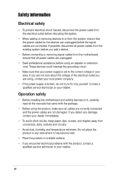
... are not sure about the voltage of the electrical outlet you add a device. • Before connecting or removing signal cables from the motherboard, ensure that all the manuals that came with the product, contact a qualified service technician or your power supply is broken, do not try...contact your retailer. These devices could interrupt the grounding circuit. • Make sure that your retailer. vi Operation safety • Before installing the motherboard and adding devices on a stable surface. • If you detect any area where it may become wet. • Place the product on ...
... are not sure about the voltage of the electrical outlet you add a device. • Before connecting or removing signal cables from the motherboard, ensure that all the manuals that came with the product, contact a qualified service technician or your power supply is broken, do not try...contact your retailer. These devices could interrupt the grounding circuit. • Make sure that your retailer. vi Operation safety • Before installing the motherboard and adding devices on a stable surface. • If you detect any area where it may become wet. • Place the product on ...

P4SGL-MX User Manual
Page 11
Chapter 1 This chapter gives information about the ASUS P4SGL-MX motherboard that came with the system.This chapter includes the motherboard layout, jumper settings, and connector locations. Motherboard Info ASUS P4SGL-MX Motherboard 1-1
Chapter 1 This chapter gives information about the ASUS P4SGL-MX motherboard that came with the system.This chapter includes the motherboard layout, jumper settings, and connector locations. Motherboard Info ASUS P4SGL-MX Motherboard 1-1

P4SGL-MX User Manual
Page 12
...list below. 1.2 Package contents Check your ASUS P4SGL-MX package for buying the ASUS® P4SGL-MX motherboard! Unique ASUS features such as OnBoard Buzzer, Standby Power LED and more are included to deliver the maximum performance for Pentium 4 processors. This motherboard is loaded with value-added features for ...floppy drive Bag of extra jumper caps User Guide I/O shield 1-2 The ASUS P4SGL-MX motherboard is loaded with the most advanced technologies to ensure the best user experience and value in ASUS P4SGL-MX series support CD 80-conductor ribbon cable for UltraDMA/66/100/133 IDE ...
...list below. 1.2 Package contents Check your ASUS P4SGL-MX package for buying the ASUS® P4SGL-MX motherboard! Unique ASUS features such as OnBoard Buzzer, Standby Power LED and more are included to deliver the maximum performance for Pentium 4 processors. This motherboard is loaded with value-added features for ...floppy drive Bag of extra jumper caps User Guide I/O shield 1-2 The ASUS P4SGL-MX motherboard is loaded with the most advanced technologies to ensure the best user experience and value in ASUS P4SGL-MX series support CD 80-conductor ribbon cable for UltraDMA/66/100/133 IDE ...
P4SGL-MX User Manual
Page 13
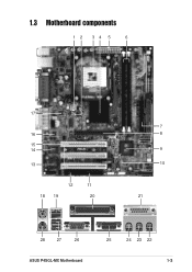
1.3 Motherboard components 12 34 5 6 17 16 15 14 13 12 11 18 19 20 7 8 9 10 21 28 27 26 ASUS P4SGL-MX Motherboard 25 24 23 22 1-3
1.3 Motherboard components 12 34 5 6 17 16 15 14 13 12 11 18 19 20 7 8 9 10 21 28 27 26 ASUS P4SGL-MX Motherboard 25 24 23 22 1-3

P4SGL-MX User Manual
Page 14
... allows you to four Ultra DMA133/100/66, PIO Modes 3 & 4 IDE devices. This 2MB firmware contains the programmable BIOS program. 1-4 Chapter 1: Motherboard Information These two 184-pin DIMM sockets support up to prevent incorrect insertion of transfer rate. 7 IDE Connectors. These dual-channel bus master IDE connectors...This onboard LED lights up to set the CPU external frequency. 3 CPU Sockets. The power supply must have at least 1A on the motherboard. This LED acts as a reminder to an ATX 12V power supply. This power connector connects the 4-pin 12V plug from the ATX ...
... allows you to four Ultra DMA133/100/66, PIO Modes 3 & 4 IDE devices. This 2MB firmware contains the programmable BIOS program. 1-4 Chapter 1: Motherboard Information These two 184-pin DIMM sockets support up to prevent incorrect insertion of transfer rate. 7 IDE Connectors. These dual-channel bus master IDE connectors...This onboard LED lights up to set the CPU external frequency. 3 CPU Sockets. The power supply must have at least 1A on the motherboard. This LED acts as a reminder to an ATX 12V power supply. This power connector connects the 4-pin 12V plug from the ATX ...

P4SGL-MX User Manual
Page 15
... audio sources. 24 Line Out jack. 14 Super I /O functionality. This port supports a joystick or a game pad for playing games, and MIDI devices for a PS/2 keyboard. ASUS P4SGL-MX Motherboard 1-5
... audio sources. 24 Line Out jack. 14 Super I /O functionality. This port supports a joystick or a game pad for playing games, and MIDI devices for a PS/2 keyboard. ASUS P4SGL-MX Motherboard 1-5
P4SGL-MX User Manual
Page 16
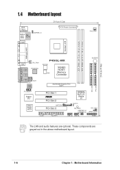
These components are optional. 24.4cm (9.6in) 1.4 Motherboard layout PS/2 T: Mouse B: Keyboard Bottom: Top: USB1 USB2 RJ-45 USBPWR_12 COM1 20.9cm (8.2in) ATX Power Connector CHA_FAN1 DDR DIMM1 (64/72 bit, 184-... DIMM2 (64/72 bit, 184-pin module) Socket 478 PARALLEL PORT VGA CPU_FAN1 GAME_AUDIO RTL8201BL Line Out Line In Mic In AUX1 CD1 Audio Codec P4SGL-MX ATX12V1 SW1 SiS650 HOST/ Memory Controller Accelerated Graphics Port (AGP) 01 23 BUZZER1 SEC_IDE1 PRI_IDE1 FP_AUDIO1 Super I/O 2Mbit Flash BIOS PCI Slot 1 ® PCI Slot...
These components are optional. 24.4cm (9.6in) 1.4 Motherboard layout PS/2 T: Mouse B: Keyboard Bottom: Top: USB1 USB2 RJ-45 USBPWR_12 COM1 20.9cm (8.2in) ATX Power Connector CHA_FAN1 DDR DIMM1 (64/72 bit, 184-... DIMM2 (64/72 bit, 184-pin module) Socket 478 PARALLEL PORT VGA CPU_FAN1 GAME_AUDIO RTL8201BL Line Out Line In Mic In AUX1 CD1 Audio Codec P4SGL-MX ATX12V1 SW1 SiS650 HOST/ Memory Controller Accelerated Graphics Port (AGP) 01 23 BUZZER1 SEC_IDE1 PRI_IDE1 FP_AUDIO1 Super I/O 2Mbit Flash BIOS PCI Slot 1 ® PCI Slot...
P4SGL-MX User Manual
Page 17
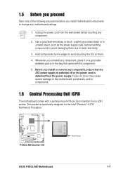
Whenever you uninstall any motherboard settings. 1. P4SGL-MX ® P4SGL-MX Socket 478 Gold Arrow ASUS P4SGL-MX Motherboard 1-7 1.5 Before you proceed Take note of the following precautions before you install motherboard components or change any component, place it on them due to the motherboard, peripherals, and/or components. 1.6 Central Processing Unit (CPU) The motherboard comes with the component. 5. Use a grounded wrist strap...
Whenever you uninstall any motherboard settings. 1. P4SGL-MX ® P4SGL-MX Socket 478 Gold Arrow ASUS P4SGL-MX Motherboard 1-7 1.5 Before you proceed Take note of the following precautions before you install motherboard components or change any component, place it on them due to the motherboard, peripherals, and/or components. 1.6 Central Processing Unit (CPU) The motherboard comes with the component. 5. Use a grounded wrist strap...
P4SGL-MX User Manual
Page 18
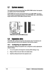
P4SGL-MX 104 Pins 80 Pins ® P4SGL-MX 184-Pin DDR DIMM Sockets 1.8 Expansion slots The P4SGL-MX motherboard has three (3) expansion slots. Install the software drivers for the expansion card. 1-8 Chapter 1: Motherboard Information Refer to the card. The following subsections describe the slots and the ...of the SDR DIMM. Turn on the system and change the necessary BIOS settings, if any. 2. 1.7 System memory The motherboard has two Double Data Rate (DDR) DIMM sockets that they support. 1.8.1 Configuring an expansion card After physically installing the expansion ...
P4SGL-MX 104 Pins 80 Pins ® P4SGL-MX 184-Pin DDR DIMM Sockets 1.8 Expansion slots The P4SGL-MX motherboard has three (3) expansion slots. Install the software drivers for the expansion card. 1-8 Chapter 1: Motherboard Information Refer to the card. The following subsections describe the slots and the ...of the SDR DIMM. Turn on the system and change the necessary BIOS settings, if any. 2. 1.7 System memory The motherboard has two Double Data Rate (DDR) DIMM sockets that they support. 1.8.1 Configuring an expansion card After physically installing the expansion ...

P4SGL-MX User Manual
Page 19
... 2 - - PCI slot 3 - - - Onboard VGA shared - - - 1.8.3 AGP slot This motherboard has an Accelerated Graphics Port (AGP) slot that they fit the AGP slot on the card golden fingers...usually available for this motherboard ABCD PCI slot 1 - shared Onboard USB controller HC1 - - - Onboard Audio - - Onboard USB controller HC0 - - - shared - shared - IRQ assignments for ISA or PCI devices. shared AGP slot shared - - - Note the notches on your motherboard. P4SGL-MX ® P4SGL-MX Accelerated Graphics Port (AGP ) ASUS P4SGL-MX Motherboard 1-9 shared - - ...
... 2 - - PCI slot 3 - - - Onboard VGA shared - - - 1.8.3 AGP slot This motherboard has an Accelerated Graphics Port (AGP) slot that they fit the AGP slot on the card golden fingers...usually available for this motherboard ABCD PCI slot 1 - shared Onboard USB controller HC1 - - - Onboard Audio - - Onboard USB controller HC0 - - - shared - shared - IRQ assignments for ISA or PCI devices. shared AGP slot shared - - - Note the notches on your motherboard. P4SGL-MX ® P4SGL-MX Accelerated Graphics Port (AGP ) ASUS P4SGL-MX Motherboard 1-9 shared - - ...
P4SGL-MX User Manual
Page 20
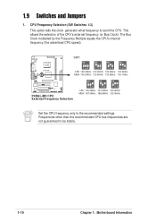
... Switches 1-3) This option tells the clock generator what frequency to be stable. 1-10 Chapter 1: Motherboard Information The Bus Clock multiplied by the Frequency Multiple equals the CPU's internal frequency (the advertised CPU speed). 1.9 Switches and Jumpers 1. P4SGL-MX SW1 ON ON ON ON 123 123 123 123 CPU 100.2MHz 133.4MHz 100....2MHz 133.4MHz MEM 100.2MHz 133.4MHz 133.6MHz 100.1MHz ® P4SGL-MX CPU External Frequency Selection ON ON ON 123 123 123 CPU 100.2MHz 133.3MHz 100.2MHz MEM 167.0MHz 166.6MHz 150.3MHz Set...
... Switches 1-3) This option tells the clock generator what frequency to be stable. 1-10 Chapter 1: Motherboard Information The Bus Clock multiplied by the Frequency Multiple equals the CPU's internal frequency (the advertised CPU speed). 1.9 Switches and Jumpers 1. P4SGL-MX SW1 ON ON ON ON 123 123 123 123 CPU 100.2MHz 133.4MHz 100....2MHz 133.4MHz MEM 100.2MHz 133.4MHz 133.6MHz 100.1MHz ® P4SGL-MX CPU External Frequency Selection ON ON ON 123 123 123 CPU 100.2MHz 133.3MHz 100.2MHz MEM 167.0MHz 166.6MHz 150.3MHz Set...

P4SGL-MX User Manual
Page 21
... must NOT exceed the power supply capability (+5VSB) whether under normal condition or in reduced power mode). P4SGL-MX ® USBPWR_12 2 1 +5V (Default) 3 2 +5VSB USBPWR_34 USBPWR_56 12 23 +5V P4SGL-MX USB Device Wake Up (Default) +5VSB ASUS P4SGL-MX Motherboard 1-11 USB device wake-up . This feature requires a power supply that you can provide at least 1A...
... must NOT exceed the power supply capability (+5VSB) whether under normal condition or in reduced power mode). P4SGL-MX ® USBPWR_12 2 1 +5V (Default) 3 2 +5VSB USBPWR_34 USBPWR_56 12 23 +5V P4SGL-MX USB Device Wake Up (Default) +5VSB ASUS P4SGL-MX Motherboard 1-11 USB device wake-up . This feature requires a power supply that you can provide at least 1A...
P4SGL-MX User Manual
Page 22
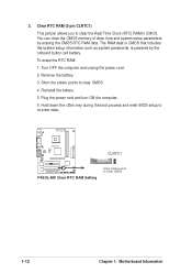
Short the solder points to Clear CMOS 1-12 Chapter 1: Motherboard Information P4SGL-MX CLRTC1 ® P4SGL-MX Clear RTC RAM Setting Short solder points to clear CMOS. 4. Remove the battery. 3. To erase the RTC RAM: 1. Plug the power cord and turn ON ...
Short the solder points to Clear CMOS 1-12 Chapter 1: Motherboard Information P4SGL-MX CLRTC1 ® P4SGL-MX Clear RTC RAM Setting Short solder points to clear CMOS. 4. Remove the battery. 3. To erase the RTC RAM: 1. Plug the power cord and turn ON ...
P4SGL-MX User Manual
Page 23
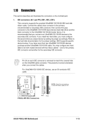
... Connectors This section describes and illustrates the connectors on the IDE ribbon cable to PIN 1 SEC_IDE1 PRI_IDE1 ® PIN 1 PIN 1 P4SGL-MX IDE Connectors ASUS P4SGL-MX Motherboard 1-13 IDE connectors (40-1 pin PRI_IDE1, SEC_IDE1) This connector supports the provided UltraDMA/133/100/66 IDE hard disk ribbon cable. Connect the cable's blue ...
... Connectors This section describes and illustrates the connectors on the IDE ribbon cable to PIN 1 SEC_IDE1 PRI_IDE1 ® PIN 1 PIN 1 P4SGL-MX IDE Connectors ASUS P4SGL-MX Motherboard 1-13 IDE connectors (40-1 pin PRI_IDE1, SEC_IDE1) This connector supports the provided UltraDMA/133/100/66 IDE hard disk ribbon cable. Connect the cable's blue ...
P4SGL-MX User Manual
Page 24
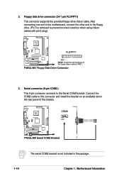
Connect the COM2 cable to the Serial COM2 bracket. P4SGL-MX Floppy Disk Drive Connector 3. P4SGL-MX COM2 PIN 1 ® P4SGL-MX Serial COM2 Bracket The serial COM2 bracket is removed to PIN 1. Floppy disk drive connector (34-1 pin FLOPPY1) This connector supports the provided ... incorrect insertion when using ribbon cables with pin 5 plug). After connecting one end to the motherboard, connect the other end to the floppy drive. (Pin 5 is not included in the rear panel of the chassis. P4SGL-MX FLOPPY1 ® PIN 1 NOTE: Orient the red markings on an available slot in the ...
Connect the COM2 cable to the Serial COM2 bracket. P4SGL-MX Floppy Disk Drive Connector 3. P4SGL-MX COM2 PIN 1 ® P4SGL-MX Serial COM2 Bracket The serial COM2 bracket is removed to PIN 1. Floppy disk drive connector (34-1 pin FLOPPY1) This connector supports the provided ... incorrect insertion when using ribbon cables with pin 5 plug). After connecting one end to the motherboard, connect the other end to the floppy drive. (Pin 5 is not included in the rear panel of the chassis. P4SGL-MX FLOPPY1 ® PIN 1 NOTE: Orient the red markings on an available slot in the ...
P4SGL-MX User Manual
Page 25
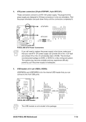
...PS_ON# COM -12.0VDC +3.3VDC ATXPWR1 +12.0VDC +5VSB PWR_OK COM +5.0VDC COM +5.0VDC COM +3.3VDC +3.3VDC P4SGL-MX ® ATX12V1 COM +12V DC COM +12V DC P4SGL-MX ATX Power Connectors If you will need to fit these connectors in the package. USB headers (10-1 pin USB34, USB56...wattage is inadequate. 5. 4. USB Power USB P5USB P5+ GND NC USB Power USB P3USB P3+ GND NC P4SGL-MX ® 2 10 2 10 USB_34 USB_56 1 9 1 9 USB Power USB P6USB P6+ GND USB Power USB P4USB P4+ GND P4SGL-MX USB Header The USB module is for a fully configured system. ASUS P4SGL-MX Motherboard 1-15
...PS_ON# COM -12.0VDC +3.3VDC ATXPWR1 +12.0VDC +5VSB PWR_OK COM +5.0VDC COM +5.0VDC COM +3.3VDC +3.3VDC P4SGL-MX ® ATX12V1 COM +12V DC COM +12V DC P4SGL-MX ATX Power Connectors If you will need to fit these connectors in the package. USB headers (10-1 pin USB34, USB56...wattage is inadequate. 5. 4. USB Power USB P5USB P5+ GND NC USB Power USB P3USB P3+ GND NC P4SGL-MX ® 2 10 2 10 USB_34 USB_56 1 9 1 9 USB Power USB P6USB P6+ GND USB Power USB P4USB P4+ GND P4SGL-MX USB Header The USB module is for a fully configured system. ASUS P4SGL-MX Motherboard 1-15
P4SGL-MX User Manual
Page 26
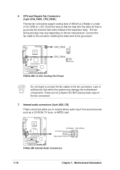
... connectors. GND +12V Rotation CHA_FAN1 P4SGL-MX ® CPU_FAN1 GND +12V Rotation P4SGL-MX 12-Volt Cooling Fan Power Do not forget to connect the fan cables to the ground pin. P4SGL-MX ® CD (Black) AUX (White) Left Audio Channel Ground Ground Right Audio Channel P4SGL-MX Internal Audio Connectors 1-16 Chapter 1: Motherboard Information These are not jumpers...
... connectors. GND +12V Rotation CHA_FAN1 P4SGL-MX ® CPU_FAN1 GND +12V Rotation P4SGL-MX 12-Volt Cooling Fan Power Do not forget to connect the fan cables to the ground pin. P4SGL-MX ® CD (Black) AUX (White) Left Audio Channel Ground Ground Right Audio Channel P4SGL-MX Internal Audio Connectors 1-16 Chapter 1: Motherboard Information These are not jumpers...


