
Motherboard DIY Troubleshooting Guide
Page 1
P4SE Motherboard
P4SE Motherboard

P4SE User Manual
Page 1
Motherboard P4SE User Guide
Motherboard P4SE User Guide

P4SE User Manual
Page 3
BIOS Information 2-1 2.1 Managing and updating your BIOS 2-2 2.1.1 Using ASUS AFLASH to find more information vii ASUS contact information vii Specifications summary ix Chapter 1 - Motherboard Info 1-1 1.1 Welcome 1-2 1.2 Package contents 1-2 1.3 Motherboard components 1-3 1.4 Motherboard layout 1-6 1.5 Before you proceed 1-7 1.6 Central Processing Unit (CPU 1-7 1.7 System memory 1-8 1.8 Expansion Slots 1-9 1.8.1 Configuring an expansion card 1-9 1.8.2 Standard Interrupt Assignments 1-9 1.9 Switches and Jumpers 1-10 1.10 Connectors...
BIOS Information 2-1 2.1 Managing and updating your BIOS 2-2 2.1.1 Using ASUS AFLASH to find more information vii ASUS contact information vii Specifications summary ix Chapter 1 - Motherboard Info 1-1 1.1 Welcome 1-2 1.2 Package contents 1-2 1.3 Motherboard components 1-3 1.4 Motherboard layout 1-6 1.5 Before you proceed 1-7 1.6 Central Processing Unit (CPU 1-7 1.7 System memory 1-8 1.8 Expansion Slots 1-9 1.8.1 Configuring an expansion card 1-9 1.8.2 Standard Interrupt Assignments 1-9 1.9 Switches and Jumpers 1-10 1.10 Connectors...

P4SE User Manual
Page 6
...ensure that the power cables for the devices are unplugged before using an adpater or extension cord. Operation safety • Before installing the motherboard and adding devices on it may become wet. • Place the product on a stable surface. • If you detect any ... not place the product in your dealer immediately. • To avoid short circuits, keep paper clips, screws, and staples away from the motherboard, ensure that came with the product, contact a qualified service technician or your retailer. Contact a qualified service technician or your local power company...
...ensure that the power cables for the devices are unplugged before using an adpater or extension cord. Operation safety • Before installing the motherboard and adding devices on it may become wet. • Place the product on a stable surface. • If you detect any ... not place the product in your dealer immediately. • To avoid short circuits, keep paper clips, screws, and staples away from the motherboard, ensure that came with the product, contact a qualified service technician or your retailer. Contact a qualified service technician or your local power company...

P4SE User Manual
Page 11
Motherboard Info ASUS P4SE Motherboard 1-1 Chapter 1 This chapter gives information about the ASUS P4SE motherboard that came with the system.This chapter includes the motherboard layout, jumper settings, and connector locations.
Motherboard Info ASUS P4SE Motherboard 1-1 Chapter 1 This chapter gives information about the ASUS P4SE motherboard that came with the system.This chapter includes the motherboard layout, jumper settings, and connector locations.

P4SE User Manual
Page 12
... ports plus headers for four more 1.2 Package contents Check your ASUS P4SE package for the following items. ASUS P4SE motherboard ATX form factor: 12 in x 8.6 in the long line of PC 2700 / 2100 / 1600 DDR (Note: PC2700 max. The ASUS P4SE motherboard delivers a host of new features and latest technology making it... another standout in ASUS P4SE support CD 1 pc. 80-conductor ribbon cable for UltraDMA/66/100/133 IDE drives 1 pc. 40-...
... ports plus headers for four more 1.2 Package contents Check your ASUS P4SE package for the following items. ASUS P4SE motherboard ATX form factor: 12 in x 8.6 in the long line of PC 2700 / 2100 / 1600 DDR (Note: PC2700 max. The ASUS P4SE motherboard delivers a host of new features and latest technology making it... another standout in ASUS P4SE support CD 1 pc. 80-conductor ribbon cable for UltraDMA/66/100/133 IDE drives 1 pc. 40-...

P4SE User Manual
Page 13
1.3 Motherboard components 1 2 3 45 6 7 8 9 10 16 15 17 14 13 12 11 18 19 25 24 23 ASUS P4SE Motherboard 22 21 20 1-3
1.3 Motherboard components 1 2 3 45 6 7 8 9 10 16 15 17 14 13 12 11 18 19 25 24 23 ASUS P4SE Motherboard 22 21 20 1-3

P4SE User Manual
Page 14
...processor, a memory controller and an integrated graphics interface. 8 IDE Connectors. This standard 20-pin connector connects to 4 banks only.) 5 ASUS EZ PlugTM Auxillary +12V connector. This SiS 645 controller integrates a high performance host interface for the floppy disk drive. These dual-channel...; Pentium® 4 478/Northwood Processor with 400 MHz system bus that include hardware and system voltage monitoring. 1-4 Chapter 1: Motherboard Information This power connector connects the 4-pin 12V plug from a standard power supply to this connector to provide sufficient power to...
...processor, a memory controller and an integrated graphics interface. 8 IDE Connectors. This standard 20-pin connector connects to 4 banks only.) 5 ASUS EZ PlugTM Auxillary +12V connector. This SiS 645 controller integrates a high performance host interface for the floppy disk drive. These dual-channel...; Pentium® 4 478/Northwood Processor with 400 MHz system bus that include hardware and system voltage monitoring. 1-4 Chapter 1: Motherboard Information This power connector connects the 4-pin 12V plug from a standard power supply to this connector to provide sufficient power to...
P4SE User Manual
Page 15
..., a scanner, or other audio sources. 22 Line Out jack. This Line Out (lime) jack connects a headphone or a speaker. 23 Serial port. ASUS P4SE Motherboard 1-5 This connector supports a joystick or a game pad for playing games, and MIDI devices for a PS/2 keyboard. This purple 6-pin connector is for... playing or editing audio files. (on the motherboard. This SiS 961B controller integrates the AC'97 Interface, four Universal Serial Bus Host controllers, two IDE Master/Slave controllers. 13 Super I ...
..., a scanner, or other audio sources. 22 Line Out jack. This Line Out (lime) jack connects a headphone or a speaker. 23 Serial port. ASUS P4SE Motherboard 1-5 This connector supports a joystick or a game pad for playing games, and MIDI devices for a PS/2 keyboard. This purple 6-pin connector is for... playing or editing audio files. (on the motherboard. This SiS 961B controller integrates the AC'97 Interface, four Universal Serial Bus Host controllers, two IDE Master/Slave controllers. 13 Super I ...

P4SE User Manual
Page 16
PRIMARY IDE JEN1 30.5cm (12.0in) 1.4 Motherboard layout PS/2KBMS T: Mouse B: Keyboard USB1 USB2 COM1 VEN1 KBPWR ...In ATX12V1 CPUFAN1 AUX1 SiS645 HOST/ Memory Controller Accelerated Graphics Port AGP PCI1 CD1 ALOUT1 IAPANEL1 PCI2 PCI3 P4SE C-Media 4CH PCI4 ® LED1 PCI5 01 23 45 SiS961B MuTLOL Media I/O CLRCMOS1 CR2032 3V Lithium... Cell CMOS Power PWRTMP1 DSW1 SPDIF_OUT1 CHASSIS1 SMB1 SMARTCON1 IR CHASFAN1 ASUS ASIC with Hardware Monitor SECONDARY IDE 2Mbit Firmware Hub MODEM1 PCI6 USBV2 USBV3 USB3 USB2 Super I/O IDELED1 ...
PRIMARY IDE JEN1 30.5cm (12.0in) 1.4 Motherboard layout PS/2KBMS T: Mouse B: Keyboard USB1 USB2 COM1 VEN1 KBPWR ...In ATX12V1 CPUFAN1 AUX1 SiS645 HOST/ Memory Controller Accelerated Graphics Port AGP PCI1 CD1 ALOUT1 IAPANEL1 PCI2 PCI3 P4SE C-Media 4CH PCI4 ® LED1 PCI5 01 23 45 SiS961B MuTLOL Media I/O CLRCMOS1 CR2032 3V Lithium... Cell CMOS Power PWRTMP1 DSW1 SPDIF_OUT1 CHASSIS1 SMB1 SMARTCON1 IR CHASFAN1 ASUS ASIC with Hardware Monitor SECONDARY IDE 2Mbit Firmware Hub MODEM1 PCI6 USBV2 USBV3 USB3 USB2 Super I/O IDELED1 ...

P4SE User Manual
Page 17
... precautions before you uninstall any component, place it on them due to static electricity. 3. Whenever you install motherboard components or change any motherboard settings. 1. Failure to do so may cause severe damage to avoid touching the ICs on a grounded antistatic...) indicates that came with the component. 5. 1.5 Before you proceed Take note of plugging in any motherboard component P4SE ® P4SE Onboard LED LED1 ON Standby Power OFF Powered Off ASUS P4SE Motherboard 1-7 Use a grounded wrist strap or touch a safely grounded object or to avoid damaging them . ...
... precautions before you uninstall any component, place it on them due to static electricity. 3. Whenever you install motherboard components or change any motherboard settings. 1. Failure to do so may cause severe damage to avoid touching the ICs on a grounded antistatic...) indicates that came with the component. 5. 1.5 Before you proceed Take note of plugging in any motherboard component P4SE ® P4SE Onboard LED LED1 ON Standby Power OFF Powered Off ASUS P4SE Motherboard 1-7 Use a grounded wrist strap or touch a safely grounded object or to avoid damaging them . ...

P4SE User Manual
Page 18
...; 4 478/Northwood Processor. A DDR DIMM is keyed with a surface mount 478-pin Zero Insertion Force (ZIF) socket. P4SE ® Gold Arrow P4SE Socket 478 1.7 System memory The motherboard has three Double Data Rate (DDR) DIMM sockets that it has a 184-pin footprint compared to the 168-pin of the... DO NOT force a DIMM into a socket to 4 banks only.) 104 Pins P4SE ® P4SE 184-Pin DDR DIMM Sockets 80 Pins 1. This socket is double notched. (Note: PC2700 max. 1.6 Central Processing Unit (CPU) The motherboard comes with a notch so that supports up to 3GB non-ECC PC2700/2100/1600...
...; 4 478/Northwood Processor. A DDR DIMM is keyed with a surface mount 478-pin Zero Insertion Force (ZIF) socket. P4SE ® Gold Arrow P4SE Socket 478 1.7 System memory The motherboard has three Double Data Rate (DDR) DIMM sockets that it has a 184-pin footprint compared to the 168-pin of the... DO NOT force a DIMM into a socket to 4 banks only.) 104 Pins P4SE ® P4SE 184-Pin DDR DIMM Sockets 80 Pins 1. This socket is double notched. (Note: PC2700 max. 1.6 Central Processing Unit (CPU) The motherboard comes with a notch so that supports up to 3GB non-ECC PC2700/2100/1600...

P4SE User Manual
Page 19
...Configuring an expansion card After physically installing the expansion card, configure the card by adjusting the software settings. 1. shared - PCI slot 6 - ASUS P4SE Motherboard 1-9 Refer to the card. shared - - Onboard USB controller HC0 - - - Otherwise, conflicts will arise between two PCI groups. shared AGP...Primary IDE Channel 15* 10 Secondary IDE Channel *These IRQs are usually available for this motherboard ABCD PCI slot 1 shared - - - 1.8 Expansion slots The P4SE motherboard has six (6) expansion slots. When using PCI cards on the system and change the ...
...Configuring an expansion card After physically installing the expansion card, configure the card by adjusting the software settings. 1. shared - PCI slot 6 - ASUS P4SE Motherboard 1-9 Refer to the card. shared - - Onboard USB controller HC0 - - - Otherwise, conflicts will arise between two PCI groups. shared AGP...Primary IDE Channel 15* 10 Secondary IDE Channel *These IRQs are usually available for this motherboard ABCD PCI slot 1 shared - - - 1.8 Expansion slots The P4SE motherboard has six (6) expansion slots. When using PCI cards on the system and change the ...

P4SE User Manual
Page 20
... to use the DIP switches. JEN1 OFF ON DSW1 ON 12345 P4SE ® 2 1 Jumper Mode P4SE JumperFree™ Mode Setting 3 2 Jumper Free (Default) The JEN jumper is adjusted through the BIOS setup instead of using the DIP switches. 1.9 Switches and jumpers The motherboard frequency is set in the OFF position. Frequency Selection 4. Frequency...
... to use the DIP switches. JEN1 OFF ON DSW1 ON 12345 P4SE ® 2 1 Jumper Mode P4SE JumperFree™ Mode Setting 3 2 Jumper Free (Default) The JEN jumper is adjusted through the BIOS setup instead of using the DIP switches. 1.9 Switches and jumpers The motherboard frequency is set in the OFF position. Frequency Selection 4. Frequency...

P4SE User Manual
Page 21
... switches, ensure that can supply at least 1A on the keyboard (the default is set to jumper mode. P4SE ® KBPWR1 2 1 +5V 3 2 +5VSB (Default) P4SE Keyboard Power Setting ASUS P4SE Motherboard 1-11 CPU Frequency Selection (DSW1 Switches 1-5) This option tells the clock generator what frequency to be stable. ...100MHz DRAM 100MHz 133MHz 150MHz 160MHz 166MHz ON 12345 ON 12345 ON 12345 ON 12345 ON 12345 ON 12345 P4SE ® CPU 105MHz DRAM 140MHz P4SE CPU External Frequency Selection 108MHz 144MHz 112MHz 149MHz 133MHz 133MHz 133MHz 166MHz 100MHz 200MHz Set the CPU frequency ...
... switches, ensure that can supply at least 1A on the keyboard (the default is set to jumper mode. P4SE ® KBPWR1 2 1 +5V 3 2 +5VSB (Default) P4SE Keyboard Power Setting ASUS P4SE Motherboard 1-11 CPU Frequency Selection (DSW1 Switches 1-5) This option tells the clock generator what frequency to be stable. ...100MHz DRAM 100MHz 133MHz 150MHz 160MHz 166MHz ON 12345 ON 12345 ON 12345 ON 12345 ON 12345 ON 12345 P4SE ® CPU 105MHz DRAM 140MHz P4SE CPU External Frequency Selection 108MHz 144MHz 112MHz 149MHz 133MHz 133MHz 133MHz 166MHz 100MHz 200MHz Set the CPU frequency ...

P4SE User Manual
Page 22
... jumper permits an increase of CPU voltage of 0.2 volts. P4SE ® USBV1 2 1 +5V (Default) 3 2 +5VSB USBV2 USBV3 12 23 P4SE USB Device Wake Up +5V (Default) +5VSB 5. Set to +5VSB to +5VSB. It is for system stability. P4SE ® VEN1 12 23 CPU Rise 0.2V Normal (Default) 1-12 P4SE CPU Voltage Setting Chapter 1: Motherboard Information
... jumper permits an increase of CPU voltage of 0.2 volts. P4SE ® USBV1 2 1 +5V (Default) 3 2 +5VSB USBV2 USBV3 12 23 P4SE USB Device Wake Up +5V (Default) +5VSB 5. Set to +5VSB to +5VSB. It is for system stability. P4SE ® VEN1 12 23 CPU Rise 0.2V Normal (Default) 1-12 P4SE CPU Voltage Setting Chapter 1: Motherboard Information
P4SE User Manual
Page 23
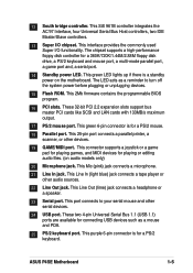
... the jumper cap from the CLRTC jumper, [1-2] and place it on jumpers [2-3] for adjusting the voltage. P4SE ® DDRVOL1 12 23 2.5V 2.7V (Default) 34 2.9V P4SE DDRVOL Setting 7. The RAM data in CMOS. Three positions are available for a few seconds. 4. The ... such as system passwords, is recommended that you keep the default setting (2.5V) for system stability. Remove the motherboard battery. 3. Replace the battery. 6. P4SE ® P4SE Clear RTC RAM ASUS P4SE Motherboard CLRCMOS1 2 1 Normal (Default) 3 2 Clear CMOS 1-13 6. It is powered by the onboard button cell...
... the jumper cap from the CLRTC jumper, [1-2] and place it on jumpers [2-3] for adjusting the voltage. P4SE ® DDRVOL1 12 23 2.5V 2.7V (Default) 34 2.9V P4SE DDRVOL Setting 7. The RAM data in CMOS. Three positions are available for a few seconds. 4. The ... such as system passwords, is recommended that you keep the default setting (2.5V) for system stability. Remove the motherboard battery. 3. Replace the battery. 6. P4SE ® P4SE Clear RTC RAM ASUS P4SE Motherboard CLRCMOS1 2 1 Normal (Default) 3 2 Clear CMOS 1-13 6. It is powered by the onboard button cell...

P4SE User Manual
Page 24
.../100/66 IDE hard disk ribbon cable. Refer to the hard disk documentation for the secondary IDE connector. 1. SECONDARY IDE PRIMARY IDE P4SE ® P4SE IDE Connectors 1-14 NOTE: Orient the red markings (usually zigzag) on the UltraDMA/100/66 cable is intentional. These are used for...the secondary IDE connector. If you connect non-UltraDMA133/100/66 devices to PIN 1. Some pins are clearly distinguished from jumpers in the Motherboard Layout. BIOS supports specific device bootup. Pin 20 on each IDE connector is recommended that you have more than two UltraDMA133/100/66 ...
.../100/66 IDE hard disk ribbon cable. Refer to the hard disk documentation for the secondary IDE connector. 1. SECONDARY IDE PRIMARY IDE P4SE ® P4SE IDE Connectors 1-14 NOTE: Orient the red markings (usually zigzag) on the UltraDMA/100/66 cable is intentional. These are used for...the secondary IDE connector. If you connect non-UltraDMA133/100/66 devices to PIN 1. Some pins are clearly distinguished from jumpers in the Motherboard Layout. BIOS supports specific device bootup. Pin 20 on each IDE connector is recommended that you have more than two UltraDMA133/100/66 ...

P4SE User Manual
Page 25
... 1. FLOPPY1 NOTE: Orient the red markings on the floppy ribbon cable to prevent incorrect insertion when using ribbon cables with pin 5 plug). P4SE ® PIN 1 P4SE Floppy Disk Drive Connector ASUS P4SE Motherboard 1-15 The read and write activities of devices connected to the primary or secondary IDE connector cause this LED to the hard...
... 1. FLOPPY1 NOTE: Orient the red markings on the floppy ribbon cable to prevent incorrect insertion when using ribbon cables with pin 5 plug). P4SE ® PIN 1 P4SE Floppy Disk Drive Connector ASUS P4SE Motherboard 1-15 The read and write activities of devices connected to the primary or secondary IDE connector cause this LED to the hard...

P4SE User Manual
Page 26
... a chassis designed with intrusion detection feature. USB3 USB2 USB Power USBP2- USBP3+ GND P4SE Front Panel USB Headers The two-port USB connector is for additional USB port connectors. Chassis open slot in the package. 1-16 Chapter 1: Motherboard Information Connect the bundled 2-port USB connector set to this lead to close the...
... a chassis designed with intrusion detection feature. USB3 USB2 USB Power USBP2- USBP3+ GND P4SE Front Panel USB Headers The two-port USB connector is for additional USB port connectors. Chassis open slot in the package. 1-16 Chapter 1: Motherboard Information Connect the bundled 2-port USB connector set to this lead to close the...


