Motherboard DIY Troubleshooting Guide
Page 6
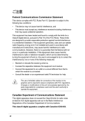
...: • This device may cause harmful interference to operate this equipment. The use of shielded cables for radio noise emissions from that to which can radiate radio frequency energy and, if not installed and used in a residential installation. Canadian Department of ...Part 15. Changes or modifications to this equipment does cause harmful interference to radio or television reception, which the receiver is required to Part 15 of the monitor to the graphics card is connected. • Consult the dealer or an experienced radio/TV technician for compliance could void the user...
...: • This device may cause harmful interference to operate this equipment. The use of shielded cables for radio noise emissions from that to which can radiate radio frequency energy and, if not installed and used in a residential installation. Canadian Department of ...Part 15. Changes or modifications to this equipment does cause harmful interference to radio or television reception, which the receiver is required to Part 15 of the monitor to the graphics card is connected. • Consult the dealer or an experienced radio/TV technician for compliance could void the user...
Motherboard DIY Troubleshooting Guide
Page 16
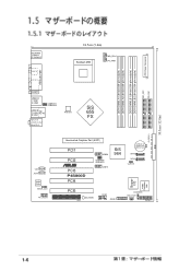
30.5cm (12.0in) ATX Power Connector PS/2KBMS T: Mouse B: Keyboard SPDIF_O 24.5cm (9.6in) Socket 478 PWR_FAN1 CPU_FAN1 SEC_IDE1 PRI_IDE1 DDR DIMM_A1 (64 bit,184-pin module) DDR DIMM_A2 (64 bit,184-pin module) DDR DIMM_B1 (64 bit,184-pin module) DDR DIMM_B2 (64 bit,184-pin module) PARALLEL PORT COM1 USB2.0 T: USB1... 655 FX FLOPPY1 CD1 AUX1 Audio Codec SPDIF_OUT FP_AUDIO Accelerated Graphics Port (AGP1) PCI1 PCI2 ® PCI3 P4S800D PCI4 USB56 USBPW56 USBPW78 USB78 SiS 964 CR2032 3V Lithium Cell CMOS Power SATA2 SATA1 CLRTC1 Super I/O 4Mbit Firmware Hub PCI5 WIFI SB_PWR1 COM2 ...
30.5cm (12.0in) ATX Power Connector PS/2KBMS T: Mouse B: Keyboard SPDIF_O 24.5cm (9.6in) Socket 478 PWR_FAN1 CPU_FAN1 SEC_IDE1 PRI_IDE1 DDR DIMM_A1 (64 bit,184-pin module) DDR DIMM_A2 (64 bit,184-pin module) DDR DIMM_B1 (64 bit,184-pin module) DDR DIMM_B2 (64 bit,184-pin module) PARALLEL PORT COM1 USB2.0 T: USB1... 655 FX FLOPPY1 CD1 AUX1 Audio Codec SPDIF_OUT FP_AUDIO Accelerated Graphics Port (AGP1) PCI1 PCI2 ® PCI3 P4S800D PCI4 USB56 USBPW56 USBPW78 USB78 SiS 964 CR2032 3V Lithium Cell CMOS Power SATA2 SATA1 CLRTC1 Super I/O 4Mbit Firmware Hub PCI5 WIFI SB_PWR1 COM2 ...
Motherboard DIY Troubleshooting Guide
Page 45
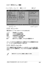
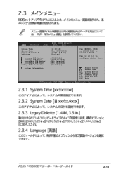
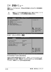
Use [+] or [-] to select a field. Select Screen Select Item +- System Time System Date Legacy Diskette A Language Primary IDE Master Primary IDE Slave Secondary IDE Master Secondary IDE Slave OnChip SATA Controller System Information [11:10:19] [Thu 03/27/2003] [1.44M, 3.5 in] [English] :[ST320413A] :[ASUS CD-S340] :[Not Detected] :[Not Detected] :[Raid Mode] Use [ENTER], [TAB] or [SHIFT-TAB] to configure system time. Change Field Tab Select Field F1 General Help F10 Save and Exit ESC Exit 2-9
Use [+] or [-] to select a field. Select Screen Select Item +- System Time System Date Legacy Diskette A Language Primary IDE Master Primary IDE Slave Secondary IDE Master Secondary IDE Slave OnChip SATA Controller System Information [11:10:19] [Thu 03/27/2003] [1.44M, 3.5 in] [English] :[ST320413A] :[ASUS CD-S340] :[Not Detected] :[Not Detected] :[Raid Mode] Use [ENTER], [TAB] or [SHIFT-TAB] to configure system time. Change Field Tab Select Field F1 General Help F10 Save and Exit ESC Exit 2-9
Motherboard DIY Troubleshooting Guide
Page 46
... SiS963/SiS964 Configuration Select Screen Select Item +- Change Option F1 General Help F10 Save and Exit ESC Exit System Time System Date Legacy Diskette A Language Primary IDE Master Primary IDE Slave Secondary IDE Master Secondary IDE Slave OnChip SATA Controller System Information [11:10:19] [Thu 03/27/2003] [1.44M, 3.5 in] [English] :[ST320413A] :[ASUS CD-S340] :[Not Detected] :[Not Detected] :[Raid Mode] Use [ENTER], [TAB] or...
... SiS963/SiS964 Configuration Select Screen Select Item +- Change Option F1 General Help F10 Save and Exit ESC Exit System Time System Date Legacy Diskette A Language Primary IDE Master Primary IDE Slave Secondary IDE Master Secondary IDE Slave OnChip SATA Controller System Information [11:10:19] [Thu 03/27/2003] [1.44M, 3.5 in] [English] :[ST320413A] :[ASUS CD-S340] :[Not Detected] :[Not Detected] :[Raid Mode] Use [ENTER], [TAB] or...
Motherboard DIY Troubleshooting Guide
Page 47
Select Screen Select Item +- System Time System Date Legacy Diskette A Language Primary IDE Master Primary IDE Slave Secondary IDE Master Secondary IDE Slave OnChip SATA Controller System Information [11:10:19] [Thu 03/27/2003] [1.44M, 3.5 in] [English] :[ST320413A] :[ASUS CD-S340] :[Not Detected] :[Not Detected] :[Raid Mode] Use [ENTER], [TAB] or [SHIFT-TAB] to configure system time. Change Field Tab Select Field F1 General Help F10 Save and Exit ESC Exit 2-11 Use [+] or [-] to select a field.
Select Screen Select Item +- System Time System Date Legacy Diskette A Language Primary IDE Master Primary IDE Slave Secondary IDE Master Secondary IDE Slave OnChip SATA Controller System Information [11:10:19] [Thu 03/27/2003] [1.44M, 3.5 in] [English] :[ST320413A] :[ASUS CD-S340] :[Not Detected] :[Not Detected] :[Raid Mode] Use [ENTER], [TAB] or [SHIFT-TAB] to configure system time. Change Field Tab Select Field F1 General Help F10 Save and Exit ESC Exit 2-11 Use [+] or [-] to select a field.
Motherboard DIY Troubleshooting Guide
Page 48
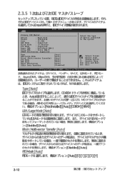
Primary IDE Master Device : Hard Disk Vendor : ST320413A Size : 20.0GB LBA Mode : Supported Block Mode : 16 Sectors PIO Mode : Supported Async DMA : MultiWord DMA-2 Ultra DMA : Ultra DMA-5 SMART Monitoring: Supported Type LBA/Large Mode Block (Multi-sector Transfer) PIO Mode DMA Mode Smart Monitoring 32Bit Data Transfer [Auto] [Auto] [Auto] [Auto] [Auto] [Auto] [Disabled] Select the type of device connected to the system. Change Option F1 General Help F10 Save and Exit ESC Exit 2-12 Select Screen Select Item +-
Primary IDE Master Device : Hard Disk Vendor : ST320413A Size : 20.0GB LBA Mode : Supported Block Mode : 16 Sectors PIO Mode : Supported Async DMA : MultiWord DMA-2 Ultra DMA : Ultra DMA-5 SMART Monitoring: Supported Type LBA/Large Mode Block (Multi-sector Transfer) PIO Mode DMA Mode Smart Monitoring 32Bit Data Transfer [Auto] [Auto] [Auto] [Auto] [Auto] [Auto] [Disabled] Select the type of device connected to the system. Change Option F1 General Help F10 Save and Exit ESC Exit 2-12 Select Screen Select Item +-
Motherboard DIY Troubleshooting Guide
Page 49
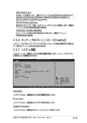
AMI BIOS Version : 08.00.08 Build Date : 03/12/03 ID : P4C81029 Processor Type Speed Count : Intel(R) Pentium(R) 4 CPU 1.73GHz : 1733 MHz : 1 System Memory Size : 256MB Select Screen Select Item +- Change Option F1 General Help F10 Save and Exit ESC Exit 2-13
AMI BIOS Version : 08.00.08 Build Date : 03/12/03 ID : P4C81029 Processor Type Speed Count : Intel(R) Pentium(R) 4 CPU 1.73GHz : 1733 MHz : 1 System Memory Size : 256MB Select Screen Select Item +- Change Option F1 General Help F10 Save and Exit ESC Exit 2-13
Motherboard DIY Troubleshooting Guide
Page 50
Change Option F1 General Help F10 Save and Exit ESC Exit 2-14 Select Screen Select Item Enter Go to Sub-screen F1 General Help F10 Save and Exit ESC Exit AI Overclock Tuner DRAM Frequency [Standard] [Auto] Configure System Frequency Voltage CPU VCore Offset +0.1V AGP VDDQ Voltage DDR Reference Voltage [Disabled] [Auto] [Auto] Select Screen Select Item +- JumperFree Configuration CPU Configuration Chipset Onboard Devices Configuration PCI PnP USB Configuration Speech Configuration Instant Music Configuration Configure CPU.
Change Option F1 General Help F10 Save and Exit ESC Exit 2-14 Select Screen Select Item Enter Go to Sub-screen F1 General Help F10 Save and Exit ESC Exit AI Overclock Tuner DRAM Frequency [Standard] [Auto] Configure System Frequency Voltage CPU VCore Offset +0.1V AGP VDDQ Voltage DDR Reference Voltage [Disabled] [Auto] [Auto] Select Screen Select Item +- JumperFree Configuration CPU Configuration Chipset Onboard Devices Configuration PCI PnP USB Configuration Speech Configuration Instant Music Configuration Configure CPU.
Motherboard DIY Troubleshooting Guide
Page 52
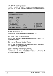
Configure advanced CPU settings Manufacturer Brand String Frequency FSB Speed : Intel(R) : Intel(R) Pentium(R) 4 CPU 1.73GHz : 1733 MHz : 533 MHz Cache L1 Cache L2 Cache L3 : 8 KB : 512 KB : 0 KB Ratio Status : Locked Ratio Actual Value : 13 VID CMOS Setting: Max CPUID Value Limit: CPU Internal Thermal Control [ 62] [Disabled] [Auto] Hyper-Threading Technology [Enabled] Select Screen Select Item +- Change Option F1 General Help F10 Save and Exit ESC Exit 2-16
Configure advanced CPU settings Manufacturer Brand String Frequency FSB Speed : Intel(R) : Intel(R) Pentium(R) 4 CPU 1.73GHz : 1733 MHz : 533 MHz Cache L1 Cache L2 Cache L3 : 8 KB : 512 KB : 0 KB Ratio Status : Locked Ratio Actual Value : 13 VID CMOS Setting: Max CPUID Value Limit: CPU Internal Thermal Control [ 62] [Disabled] [Auto] Hyper-Threading Technology [Enabled] Select Screen Select Item +- Change Option F1 General Help F10 Save and Exit ESC Exit 2-16
Motherboard DIY Troubleshooting Guide
Page 53
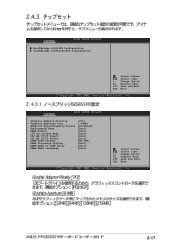
... NorthBridge SiS655FX Configuration SouthBridge SiS963/SiS964 Configuration Select Screen Select Item +- Change Option F1 General Help F10 Save and Exit ESC Exit Graphics Adapter Priority Graphics Aperture Size Advanced HyperStreaming Engine Performance Mode DRAM Timing 128 Bit Access Mode Ch0 MA 1T/2T Select Ch1 MA 1T/2T Select DRAM CAS# Latency DRAM Precharge Display DRAM RAS# to CAS# Delay DRAM RAS# Precharge [PCI] [ 64MB] [Disabled] [Auto] [Auto] [Auto] [Auto] [Auto] [By SPD] [Auto] [Auto] [Auto] Select Screen Select...
... NorthBridge SiS655FX Configuration SouthBridge SiS963/SiS964 Configuration Select Screen Select Item +- Change Option F1 General Help F10 Save and Exit ESC Exit Graphics Adapter Priority Graphics Aperture Size Advanced HyperStreaming Engine Performance Mode DRAM Timing 128 Bit Access Mode Ch0 MA 1T/2T Select Ch1 MA 1T/2T Select DRAM CAS# Latency DRAM Precharge Display DRAM RAS# to CAS# Delay DRAM RAS# Precharge [PCI] [ 64MB] [Disabled] [Auto] [Auto] [Auto] [Auto] [Auto] [By SPD] [Auto] [Auto] [Auto] Select Screen Select...
Motherboard DIY Troubleshooting Guide
Page 55
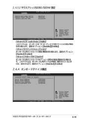
Change Option F1 General Help F10 Save and Exit ESC Exit Configure Win637 Super IO Chipset Serial Port1 Address Serial Port2 Address Parallel Port Address OnBoard Game/MIDI Port [3F8/IRQ4] [2F8/IRQ3] [Disabled] [Disabled] Select Screen Select Item +- Change Option F1 General Help F10 Save and Exit ESC Exit 2-19 Onboard AC97 Audio Device Onboard SiS900 LAN Device Onboard LAN Boot ROM [Enabled] [Enabled] [Disabled] Select Screen Select Item +-
Change Option F1 General Help F10 Save and Exit ESC Exit Configure Win637 Super IO Chipset Serial Port1 Address Serial Port2 Address Parallel Port Address OnBoard Game/MIDI Port [3F8/IRQ4] [2F8/IRQ3] [Disabled] [Disabled] Select Screen Select Item +- Change Option F1 General Help F10 Save and Exit ESC Exit 2-19 Onboard AC97 Audio Device Onboard SiS900 LAN Device Onboard LAN Boot ROM [Enabled] [Enabled] [Disabled] Select Screen Select Item +-
Motherboard DIY Troubleshooting Guide
Page 57
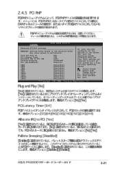
...: Setting wrong values in the system. Change Option F1 General Help F10 Save and Exit ESC Exit 2-21 Plug and Play OS PCI Latency Timer Allocate IRQ to PCI VGA Palette Snooping PCI IDE BusMaster [No] [64] [Yes] [Disabled] [Enabled] IRQ3 IRQ4 IRQ5 IRQ7 IRQ9 IRQ10 IRQ11 IRQ14 IRQ15 [Available] [Available] [Available] [Available] [Available] [Available] [Available] [Available] [Available] NO: Lets the bIOS configure...
...: Setting wrong values in the system. Change Option F1 General Help F10 Save and Exit ESC Exit 2-21 Plug and Play OS PCI Latency Timer Allocate IRQ to PCI VGA Palette Snooping PCI IDE BusMaster [No] [64] [Yes] [Disabled] [Enabled] IRQ3 IRQ4 IRQ5 IRQ7 IRQ9 IRQ10 IRQ11 IRQ14 IRQ15 [Available] [Available] [Available] [Available] [Available] [Available] [Available] [Available] [Available] NO: Lets the bIOS configure...
Motherboard DIY Troubleshooting Guide
Page 58
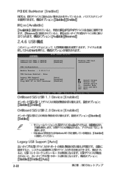
Change Option F1 General Help F10 Save and Exit ESC Exit 2-22 OnBoard SiS USB1.1 DEVICE OnBoard SiS USB2.0 DEVICE [Enabled] [Enabled] USB Configuration Module Version : 2.23.0-7.4 USB Devices Enabled : None Legacy USB Support USB 2.0 Controller Mode Stop EHCI HC in OHCI handover [Auto] [HiSpeed] [Enabled] Enables USB host controllers. Select Screen Select Item +-
Change Option F1 General Help F10 Save and Exit ESC Exit 2-22 OnBoard SiS USB1.1 DEVICE OnBoard SiS USB2.0 DEVICE [Enabled] [Enabled] USB Configuration Module Version : 2.23.0-7.4 USB Devices Enabled : None Legacy USB Support USB 2.0 Controller Mode Stop EHCI HC in OHCI handover [Auto] [HiSpeed] [Enabled] Enables USB host controllers. Select Screen Select Item +-
Motherboard DIY Troubleshooting Guide
Page 60
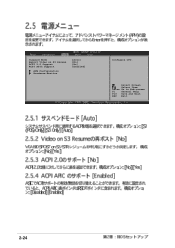
Suspend Mode Repost Video on S3 Resume ACPI 2.0 Support ACPI APIC Support APM Configuration Hardware Monitor [Auto] [No] [No] [Enabled] Configure CPU. Select Screen Select Item Enter Go to Sub-screen F1 General Help F10 Save and Exit ESC Exit 2-24
Suspend Mode Repost Video on S3 Resume ACPI 2.0 Support ACPI APIC Support APM Configuration Hardware Monitor [Auto] [No] [No] [Enabled] Configure CPU. Select Screen Select Item Enter Go to Sub-screen F1 General Help F10 Save and Exit ESC Exit 2-24
Motherboard DIY Troubleshooting Guide
Page 61
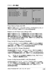
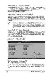
Select Screen Select Item +- Power Button Mode Restore on AC Power Loss Power On By PS/2 Keyboard Power On By PS/2 Mouse Power On By Internal MAC LAN Power On By PCI Devices Power On By External Modem Power On By RTC Alarm [On/Off] [Always OFF] [Disabled] [Disabled] [Disabled] [Disabled] [Disabled] [Disabled] Enabled or disable APM. Change Option F1 General Help F10 Save and Exit ESC Exit 2-25
Select Screen Select Item +- Power Button Mode Restore on AC Power Loss Power On By PS/2 Keyboard Power On By PS/2 Mouse Power On By Internal MAC LAN Power On By PCI Devices Power On By External Modem Power On By RTC Alarm [On/Off] [Always OFF] [Disabled] [Disabled] [Disabled] [Disabled] [Disabled] [Disabled] Enabled or disable APM. Change Option F1 General Help F10 Save and Exit ESC Exit 2-25
Motherboard DIY Troubleshooting Guide
Page 62
Change Option F1 General Help F10 Save and Exit ESC Exit 2-26 Hardware Monitor CPU Temperature MB Temperature CPU Fan Speed Chassis Fan Speed Power Fan Speed CPU Fan Control VCORE Voltage 3.3V Voltage 5V Voltage 12V Voltage [44°C/111°F] [36°C/96.5°F] [2250RPM] [XXX RPM] [XXX RPM] [Disabled] [1.550V] [3.386V] [4.890V] [11.900V] Select Screen Select Item +-
Change Option F1 General Help F10 Save and Exit ESC Exit 2-26 Hardware Monitor CPU Temperature MB Temperature CPU Fan Speed Chassis Fan Speed Power Fan Speed CPU Fan Control VCORE Voltage 3.3V Voltage 5V Voltage 12V Voltage [44°C/111°F] [36°C/96.5°F] [2250RPM] [XXX RPM] [XXX RPM] [Disabled] [1.550V] [3.386V] [4.890V] [11.900V] Select Screen Select Item +-
Motherboard DIY Troubleshooting Guide
Page 64
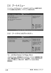
Change Option F1 General Help F10 Save and Exit ESC Exit 2-28 A device enclosed in parenthesis has been disabled in the corresponding type menu. Select Screen Select Item +- Select Screen Select Item Enter Go to Sub-screen F1 General Help F10 Save and Exit ESC Exit Boot Device Priority 1st Boot Device 2nd Boot Device 3rd Boot Device [First Floppy Drive] [PM-ST320413A] [PS-ASUS CD-S340] Specifies the boot sequence from the available devices. Boot Settings Boot Device Priority Hard Disk Drives Boot Settings Configuration Security Specifies the Boot Device Priority sequence.
Change Option F1 General Help F10 Save and Exit ESC Exit 2-28 A device enclosed in parenthesis has been disabled in the corresponding type menu. Select Screen Select Item +- Select Screen Select Item Enter Go to Sub-screen F1 General Help F10 Save and Exit ESC Exit Boot Device Priority 1st Boot Device 2nd Boot Device 3rd Boot Device [First Floppy Drive] [PM-ST320413A] [PS-ASUS CD-S340] Specifies the boot sequence from the available devices. Boot Settings Boot Device Priority Hard Disk Drives Boot Settings Configuration Security Specifies the Boot Device Priority sequence.
Motherboard DIY Troubleshooting Guide
Page 65
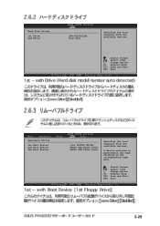
Select Screen Select Item +- Select Screen Select Item +- Change Option F1 General Help F10 Save and Exit ESC Exit Removable Drives 1st Boot Device 2nd Boot Device 3rd Boot Device [1st FLOPPY DRIVE] [ASUS USB Flash Disk] [ASUS USB Flash Disk] Specifies the boot sequence from the available devices. Change Option F1 General Help F10 Save and Exit ESC Exit 2-29 A device enclosed in parenthesis has been disabled in the corresponding type menu. Hard Disk Drives 1st Drive 2nd Drive [PM-ST320413A] [SiS 964] Specifies the boot sequence from the available devices.
Select Screen Select Item +- Select Screen Select Item +- Change Option F1 General Help F10 Save and Exit ESC Exit Removable Drives 1st Boot Device 2nd Boot Device 3rd Boot Device [1st FLOPPY DRIVE] [ASUS USB Flash Disk] [ASUS USB Flash Disk] Specifies the boot sequence from the available devices. Change Option F1 General Help F10 Save and Exit ESC Exit 2-29 A device enclosed in parenthesis has been disabled in the corresponding type menu. Hard Disk Drives 1st Drive 2nd Drive [PM-ST320413A] [SiS 964] Specifies the boot sequence from the available devices.
Motherboard DIY Troubleshooting Guide
Page 66
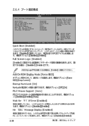
Select Screen Select Item +- Boot Settings Configuration Quick Boot Full Screen Logo Add On ROM Display Mode Bootup Num-Lock PS/2 Mouse Support Wait for 'F1' If Error Hit 'DEL' Message Display Interrupt 19 Capture [Enabled] [Enabled] [Force BIOS] [On] [Auto] [Enabled] [Enabled] [Disabled] Allows BIOS to boot the system. Change Option F1 General Help F10 Save and Exit ESC Exit 2-30 This will decrease the time needed to skip certain tests while booting.
Select Screen Select Item +- Boot Settings Configuration Quick Boot Full Screen Logo Add On ROM Display Mode Bootup Num-Lock PS/2 Mouse Support Wait for 'F1' If Error Hit 'DEL' Message Display Interrupt 19 Capture [Enabled] [Enabled] [Force BIOS] [On] [Auto] [Enabled] [Enabled] [Disabled] Allows BIOS to boot the system. Change Option F1 General Help F10 Save and Exit ESC Exit 2-30 This will decrease the time needed to skip certain tests while booting.
Motherboard DIY Troubleshooting Guide
Page 67
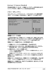
Change Option F1 General Help F10 Save and Exit ESC Exit 2-31 Select Screen Select Item +- Security Settings Supervisor Password User Password Change Supervisor Password Change User Password Clear User Password Not Installed Not Installed to disable password. again to change password.
Change Option F1 General Help F10 Save and Exit ESC Exit 2-31 Select Screen Select Item +- Security Settings Supervisor Password User Password Change Supervisor Password Change User Password Clear User Password Not Installed Not Installed to disable password. again to change password.


