
P4S333 English Manual
Page 4
... Chapter 3: Powering up 3-1 3.1 Starting up for the first time 3-1 3.2 Vocal POST Messages 3-2 3.3 Powering off the computer 3-4 Chapter 4: BIOS setup 4-1 4.1 Managing and updating your BIOS 4-1 4.1.1 Using the computer system for the first time 4-1 4.1.2 Updating BIOS procedures 4-3 4.2 BIOS Setup program 4-5 4.2.1 BIOS menu bar 4-6 4.2.2 Legend bar 4-6 4.3 Main Menu 4-8 4.3.1 Primary and Secondary Master/Slave 4-9 4.3.2 Keyboard Features 4-13 4.4 Advanced Menu...
... Chapter 3: Powering up 3-1 3.1 Starting up for the first time 3-1 3.2 Vocal POST Messages 3-2 3.3 Powering off the computer 3-4 Chapter 4: BIOS setup 4-1 4.1 Managing and updating your BIOS 4-1 4.1.1 Using the computer system for the first time 4-1 4.1.2 Updating BIOS procedures 4-3 4.2 BIOS Setup program 4-5 4.2.1 BIOS menu bar 4-6 4.2.2 Legend bar 4-6 4.3 Main Menu 4-8 4.3.1 Primary and Secondary Master/Slave 4-9 4.3.2 Keyboard Features 4-13 4.4 Advanced Menu...

P4S333 English Manual
Page 8
... BIOS beep codes. • Chapter 4: BIOS setup This chapter tells how to perform when installing system components. It includes description of the support CD that comes with the motherboard package. • Glossary This part lists the technical terms that you need when installing the ASUS P4S333 ...motherboard. How this document. About this guide This user guide contains the information you have to change system settings through the BIOS Setup menus.
... BIOS beep codes. • Chapter 4: BIOS setup This chapter tells how to perform when installing system components. It includes description of the support CD that comes with the motherboard package. • Glossary This part lists the technical terms that you need when installing the ASUS P4S333 ...motherboard. How this document. About this guide This user guide contains the information you have to change system settings through the BIOS Setup menus.

P4S333 English Manual
Page 15
...capacity storage through the sophisticated SD and MS devices. 1.3.2 Value-added solutions Overclocking The P4S333 overclocking features: • adjustable CPU frequency multiple in BIOS using the ASUS JumperFree™ solution • adjustable FSB/MEM frequency ratio • Stepless Frequency Selection...optimized system performance through BIOS built-in optimization mode • adjustable CPU VCORE and DDR memory voltage ASUS iPanel support The motherboard supports the ASUS iPanel to customize the voice messages, and provides multi-language support. ASUS P4S333 motherboard user guide 1-3...
...capacity storage through the sophisticated SD and MS devices. 1.3.2 Value-added solutions Overclocking The P4S333 overclocking features: • adjustable CPU frequency multiple in BIOS using the ASUS JumperFree™ solution • adjustable FSB/MEM frequency ratio • Stepless Frequency Selection...optimized system performance through BIOS built-in optimization mode • adjustable CPU VCORE and DDR memory voltage ASUS iPanel support The motherboard supports the ASUS iPanel to customize the voice messages, and provides multi-language support. ASUS P4S333 motherboard user guide 1-3...

P4S333 English Manual
Page 19
...15 ACR slot. This Low Pin Count (LPC) interface provides the commonly used Super I /O controller. This 2Mb firmware contains the programmable BIOS program. 14 Onboard LED. This C-Media 6-channel PCI audio chip supports legacy audio and HRTF 3D positional audio functions. This 25-pin port...SCSI or LAN cards with the South Bridge controller to fully support 10BASE-T/100BASE-TX Fast Ethernet networking protocols. (on audio models only) ASUS P4S333 motherboard user guide 1-7 This Advanced Communication Riser slot is for a 360K/720K/1.44M/ 2.88M floppy disk drive, a multi-mode parallel...
...15 ACR slot. This Low Pin Count (LPC) interface provides the commonly used Super I /O controller. This 2Mb firmware contains the programmable BIOS program. 14 Onboard LED. This C-Media 6-channel PCI audio chip supports legacy audio and HRTF 3D positional audio functions. This 25-pin port...SCSI or LAN cards with the South Bridge controller to fully support 10BASE-T/100BASE-TX Fast Ethernet networking protocols. (on audio models only) ASUS P4S333 motherboard user guide 1-7 This Advanced Communication Riser slot is for a 360K/720K/1.44M/ 2.88M floppy disk drive, a multi-mode parallel...

P4S333 English Manual
Page 35
... to unplug the power cord before adding or removing expansion cards. Keep the screw for information on the system and change the necessary BIOS settings, if any. Refer to install expansion cards. 2.6 Expansion slots In the future, you may cause you removed earlier. 6. ...4 for later use . Before installing the expansion card, read the documentation that they support. Assign an IRQ to install an expansion card. 1. ASUS P4S333 motherboard user guide 2-13 Remove the system unit cover (if your motherboard is completely seated on the slot. 5. The motherboard has six PCI slots...
... to unplug the power cord before adding or removing expansion cards. Keep the screw for information on the system and change the necessary BIOS settings, if any. Refer to install expansion cards. 2.6 Expansion slots In the future, you may cause you removed earlier. 6. ...4 for later use . Before installing the expansion card, read the documentation that they support. Assign an IRQ to install an expansion card. 1. ASUS P4S333 motherboard user guide 2-13 Remove the system unit cover (if your motherboard is completely seated on the slot. 5. The motherboard has six PCI slots...

P4S333 English Manual
Page 39
.... Frequency Selection 2. OFF ON DSW1 ON 12345 P4S333 ® P4S333 DIP Switches 1. Frequency Selection 4. JEN1 OFF ON DSW1 ON 12345 P4S333 ® 2 1 Jumper Mode P4S333 JumperFree™ Mode Setting 3 2 Jumper Free (Default) The JEN jumper is adjusted through the BIOS setup instead of using the DIP switches. ASUS P4S333 motherboard user guide 2-17 The white block represents...
.... Frequency Selection 2. OFF ON DSW1 ON 12345 P4S333 ® P4S333 DIP Switches 1. Frequency Selection 4. JEN1 OFF ON DSW1 ON 12345 P4S333 ® 2 1 Jumper Mode P4S333 JumperFree™ Mode Setting 3 2 Jumper Free (Default) The JEN jumper is adjusted through the BIOS setup instead of using the DIP switches. ASUS P4S333 motherboard user guide 2-17 The white block represents...

P4S333 English Manual
Page 40
... ON 12345 ON 12345 CPU 100MHz 100MHz 100MHz 100MHz 100MHz DRAM 100MHz 133MHz 150MHz 160MHz 166MHz P4S333 ® CPU 105MHz 108MHz 112MHz 133MHz 133MHz DRAM 140MHz 144MHz 149MHz 133MHz 166MHz P4S333 CPU External Frequency Selection Set the CPU frequency only to be stable. 3. Keyboard power (3-pin... KBPWR1) This jumper allows you press a key on the +5VSB lead, and a corresponding setting in the BIOS (see section 4.5.1 Power Up Control). ...
... ON 12345 ON 12345 CPU 100MHz 100MHz 100MHz 100MHz 100MHz DRAM 100MHz 133MHz 150MHz 160MHz 166MHz P4S333 ® CPU 105MHz 108MHz 112MHz 133MHz 133MHz DRAM 140MHz 144MHz 149MHz 133MHz 166MHz P4S333 CPU External Frequency Selection Set the CPU frequency only to be stable. 3. Keyboard power (3-pin... KBPWR1) This jumper allows you press a key on the +5VSB lead, and a corresponding setting in the BIOS (see section 4.5.1 Power Up Control). ...

P4S333 English Manual
Page 43
... boot process and enter BIOS setup to clear the Real Time Clock (RTC) RAM in CMOS, that include system setup information such as system passwords, is recommended that you keep the default setting (Normal) for system stability. P4S333 ® P4S333 Clear RTC RAM CLRCMOS1 12 23 Normal (Default) Clear CMOS ASUS P4S333 motherboard user guide...
... boot process and enter BIOS setup to clear the Real Time Clock (RTC) RAM in CMOS, that include system setup information such as system passwords, is recommended that you keep the default setting (Normal) for system stability. P4S333 ® P4S333 Clear RTC RAM CLRCMOS1 12 23 Normal (Default) Clear CMOS ASUS P4S333 motherboard user guide...
P4S333 English Manual
Page 45
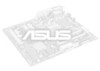
If you connect the cables. 2. Secondary IDE Connector Primary IDE Connector P4S333 ® P4S333 IDE Connectors NOTE: Orient the red markings (usually zigzag) on each IDE connector is intentional. PIN 1 For UltraDMA/100/66 IDE devices, use an 80-... IDE ribbon cable to the hard disk documentation for the jumper settings. The hole near the blue connector on the UltraDMA cable connector. ASUS P4S333 motherboard user guide 2-23 BIOS supports specific device bootup. You may configure two hard disks to match the covered hole on the UltraDMA/100/66 cable is removed...
If you connect the cables. 2. Secondary IDE Connector Primary IDE Connector P4S333 ® P4S333 IDE Connectors NOTE: Orient the red markings (usually zigzag) on each IDE connector is intentional. PIN 1 For UltraDMA/100/66 IDE devices, use an 80-... IDE ribbon cable to the hard disk documentation for the jumper settings. The hole near the blue connector on the UltraDMA cable connector. ASUS P4S333 motherboard user guide 2-23 BIOS supports specific device bootup. You may configure two hard disks to match the covered hole on the UltraDMA/100/66 cable is removed...

P4S333 English Manual
Page 53
... in BIOS to the pin definitions. Smart Card Reader connector (14-1 pin SMARTCON1) (optional) This connector accommodates a Smart Card Reader that allows you to a small opening on system chassis that support this feature. IR 1 P4S333 ® P4S333 Infrared Module Connector +5V IRRX GND IRTX Front View Back View IRTX +5V GND (NC) IRRX ASUS P4S333...
... in BIOS to the pin definitions. Smart Card Reader connector (14-1 pin SMARTCON1) (optional) This connector accommodates a Smart Card Reader that allows you to a small opening on system chassis that support this feature. IR 1 P4S333 ® P4S333 Infrared Module Connector +5V IRRX GND IRTX Front View Back View IRTX +5V GND (NC) IRRX ASUS P4S333...

P4S333 English Manual
Page 56
... is ON, when there is received. Pressing the power switch turns the system between ON and SLEEP, or ON and SOFT OFF, depending on the BIOS or OS settings. The normal status for this 2-pin connector. • ATX Power Switch / Soft-Off Switch Lead (2-pin PWRBTN) This connector connects a switch that...
... is ON, when there is received. Pressing the power switch turns the system between ON and SLEEP, or ON and SOFT OFF, depending on the BIOS or OS settings. The normal status for this 2-pin connector. • ATX Power Switch / Soft-Off Switch Lead (2-pin PWRBTN) This connector connects a switch that...

P4S333 English Manual
Page 57
Chapter 3 This chapter describes the power up Powering up sequence and gives information on the BIOS beep codes.
Chapter 3 This chapter describes the power up Powering up sequence and gives information on the BIOS beep codes.
P4S333 English Manual
Page 59
... green after the system LED turns on the screen. The system then runs the power-on the system front panel case lights up for assistance. ASUS P4S333 motherboard user guide 3-1 System running , the BIOS beeps or additional messages appear on . If your retailer for the first time 1. You will not hear the... BIOS beeps when the ASUS POST Reporter™ is working Meaning No error during POST No DRAM installed or detected Video card not found or video card memory bad CPU...
... green after the system LED turns on the screen. The system then runs the power-on the system front panel case lights up for assistance. ASUS P4S333 motherboard user guide 3-1 System running , the BIOS beeps or additional messages appear on . If your retailer for the first time 1. You will not hear the... BIOS beeps when the ASUS POST Reporter™ is working Meaning No error during POST No DRAM installed or detected Video card not found or video card memory bad CPU...

P4S333 English Manual
Page 60
... failed VGA test • Install a PCI VGA card into the AGP slot. • Make sure that came with your CPU settings in BIOS and make sure you only set to section "2.3 System memory" for assistance. Following is not defective. System failed memory test • Install ...are not defective. • Refer to the recommended settings. System failed CPU test • Check the CPU if properly installed. • Call ASUS technical support for instruction on installing a DIMM. POST Message Action No CPU installed • Install an Intel Pentium 4 478/Northwood Processor into ...
... failed VGA test • Install a PCI VGA card into the AGP slot. • Make sure that came with your CPU settings in BIOS and make sure you only set to section "2.3 System memory" for assistance. Following is not defective. System failed memory test • Install ...are not defective. • Refer to the recommended settings. System failed CPU test • Check the CPU if properly installed. • Call ASUS technical support for instruction on installing a DIMM. POST Message Action No CPU installed • Install an Intel Pentium 4 478/Northwood Processor into ...

P4S333 English Manual
Page 61
...make sure it turns on after you applied power to the one of the IDE connectors on the motherboard. • See section "2.8 Connectors." ASUS P4S333 motherboard user guide 3-3 No floppy disk detected • Make sure you have connected a floppy disk to the purple PS/2 connector on page ... Self Test • No action required Computer now booting from operating • No action required system You may disable the ASUS POST Reporter™ in the BIOS setup. POST Message Action No keyboard detected • Check your power supply and make sure it is not defective. •...
...make sure it turns on after you applied power to the one of the IDE connectors on the motherboard. • See section "2.8 Connectors." ASUS P4S333 motherboard user guide 3-3 No floppy disk detected • Make sure you have connected a floppy disk to the purple PS/2 connector on page ... Self Test • No action required Computer now booting from operating • No action required system You may disable the ASUS POST Reporter™ in the BIOS setup. POST Message Action No keyboard detected • Check your power supply and make sure it is not defective. •...

P4S333 English Manual
Page 63
Chapter 4 This chapter tells how to change system settings through the BIOS Setup menus. BIOS setup Detailed descriptions of the BIOS parameters are also provided.
Chapter 4 This chapter tells how to change system settings through the BIOS Setup menus. BIOS setup Detailed descriptions of the BIOS parameters are also provided.

P4S333 English Manual
Page 65
AFLASH.EXE is not supported by the ACPI BIOS and therefore, cannot be loaded when you boot from the floppy disk. ASUS P4S333 motherboard user guide 4-1 Reboot the computer from the hard drive. It does not work with a Flash Memory Writer utility (AFLASH.EXE) to a bootable floppy disk ...
AFLASH.EXE is not supported by the ACPI BIOS and therefore, cannot be loaded when you boot from the floppy disk. ASUS P4S333 motherboard user guide 4-1 Reboot the computer from the hard drive. It does not work with a Flash Memory Writer utility (AFLASH.EXE) to a bootable floppy disk ...

P4S333 English Manual
Page 66
Select 1. Save Current BIOS to File from the Main menu and press . 5. Type a filename and the path, for example, A:\XXX-XX.XXX, then press . 4-2 Chapter 4: BIOS Setup The Save Current BIOS To File screen appears. 6.
Select 1. Save Current BIOS to File from the Main menu and press . 5. Type a filename and the path, for example, A:\XXX-XX.XXX, then press . 4-2 Chapter 4: BIOS Setup The Save Current BIOS To File screen appears. 6.

P4S333 English Manual
Page 67
ASUS P4S333 motherboard user guide 4-3 The Update BIOS Including Boot Block and ESCD screen appears. 5. At the "A:\" prompt, type AFLASH and then press . 4. When prompted to confirm the BIOS update, press Y to the boot floppy disk you created earlier. 2. Download an updated ASUS BIOS file from the floppy disk.... 3. Boot from the Internet (WWW or FTP) (see ASUS CONTACT INFORMATION on page x for example, A:\XXX-XX....
ASUS P4S333 motherboard user guide 4-3 The Update BIOS Including Boot Block and ESCD screen appears. 5. At the "A:\" prompt, type AFLASH and then press . 4. When prompted to confirm the BIOS update, press Y to the boot floppy disk you created earlier. 2. Download an updated ASUS BIOS file from the floppy disk.... 3. Boot from the Internet (WWW or FTP) (see ASUS CONTACT INFORMATION on page x for example, A:\XXX-XX....

P4S333 English Manual
Page 68
... updated automatically only when necessary. If this may not boot. If the Flash Memory Writer utility is not able to successfully update a complete BIOS file, the system may cause boot problems. Just repeat the process, and if the problem persists, load the original... BIOS file you encounter problems while updating the new BIOS, DO NOT turn off the system because this happens, call the ASUS service center for support. 4-4 Chapter 4: BIOS Setup Follow the onscreen instructions to program the new...
... updated automatically only when necessary. If this may not boot. If the Flash Memory Writer utility is not able to successfully update a complete BIOS file, the system may cause boot problems. Just repeat the process, and if the problem persists, load the original... BIOS file you encounter problems while updating the new BIOS, DO NOT turn off the system because this happens, call the ASUS service center for support. 4-4 Chapter 4: BIOS Setup Follow the onscreen instructions to program the new...


