
P4R800-V Deluxe User Manual
Page 14
Chapter summary 1.1 Welcome 1-1 1.2 Package contents 1-1 1.3 Special features 1-2 ASUS P4R800-V Deluxe motherboard
Chapter summary 1.1 Welcome 1-1 1.2 Package contents 1-1 1.3 Special features 1-2 ASUS P4R800-V Deluxe motherboard

P4R800-V Deluxe User Manual
Page 15
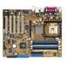
...devices on it another standout in your package with the list below. 1.2 Package contents Check your retailer. ASUS P4R800-V Deluxe motherboard user guide 1-1 The ASUS P4R800-V Deluxe motherboard delivers a host of new features and latest technologies making it , check the items in the long ...line of the above items is damaged or missing, contact your P4R800-V Deluxe package for the following items. ASUS P4R800-V Deluxe motherboard ASUS P4R800-V series support CD 2 x SATA cable 2 x SATA power cable 1 x 80-conductor ribbon cables for UltraDMA...
...devices on it another standout in your package with the list below. 1.2 Package contents Check your retailer. ASUS P4R800-V Deluxe motherboard user guide 1-1 The ASUS P4R800-V Deluxe motherboard delivers a host of new features and latest technologies making it , check the items in the long ...line of the above items is damaged or missing, contact your P4R800-V Deluxe package for the following items. ASUS P4R800-V Deluxe motherboard ASUS P4R800-V series support CD 2 x SATA cable 2 x SATA power cable 1 x 80-conductor ribbon cables for UltraDMA...

P4R800-V Deluxe User Manual
Page 17
..., musicians, and gamers. Serial ATA solution The embedded SiS 180 controller supports two Serial ATA (SATA) interface, a revolutionary replacement of the Parallel ATA storage interface. ASUS P4R800-V Deluxe motherboard user guide 1-3 The integrated graphics also supports TV out function via the S-Video and composite ports in the IGP chipset is the industry's highest...
..., musicians, and gamers. Serial ATA solution The embedded SiS 180 controller supports two Serial ATA (SATA) interface, a revolutionary replacement of the Parallel ATA storage interface. ASUS P4R800-V Deluxe motherboard user guide 1-3 The integrated graphics also supports TV out function via the S-Video and composite ports in the IGP chipset is the industry's highest...

P4R800-V Deluxe User Manual
Page 19
...) feature to save the extra cost of a stand-alone AP. The ASUS MyLogo2 is specifically designed for the ASUS WiFi-b™ add-on card comes with customizable boot logos. feature of boot errors, if any. ASUS P4R800-V Deluxe motherboard user guide 1-5 The bundled Winbond Voice Editor software lets you to ...2-17. Supported languages include English, German, and Japanese. See page 5-13. C.P.R. (CPU Parameter Recall) The C.P.R. See page 3-2. Wi-Fi slot The ASUS Wi-Fi slot is based on the IEEE 802.11b/g wireless standard and is automatically installed when you install the...
...) feature to save the extra cost of a stand-alone AP. The ASUS MyLogo2 is specifically designed for the ASUS WiFi-b™ add-on card comes with customizable boot logos. feature of boot errors, if any. ASUS P4R800-V Deluxe motherboard user guide 1-5 The bundled Winbond Voice Editor software lets you to ...2-17. Supported languages include English, German, and Japanese. See page 5-13. C.P.R. (CPU Parameter Recall) The C.P.R. See page 3-2. Wi-Fi slot The ASUS Wi-Fi slot is based on the IEEE 802.11b/g wireless standard and is automatically installed when you install the...

P4R800-V Deluxe User Manual
Page 22
Chapter summary 2.1 Before you proceed 2-1 2.2 Motherboard layout 2-2 2.3 Central Processing Unit (CPU 2-5 2.4 System memory 2-10 2.5 Expansion slots 2-14 2.6 Jumpers 2-18 2.7 Connectors 2-20 ASUS P4R800-V Deluxe motherboard
Chapter summary 2.1 Before you proceed 2-1 2.2 Motherboard layout 2-2 2.3 Central Processing Unit (CPU 2-5 2.4 System memory 2-10 2.5 Expansion slots 2-14 2.6 Jumpers 2-18 2.7 Connectors 2-20 ASUS P4R800-V Deluxe motherboard

P4R800-V Deluxe User Manual
Page 23
... static electricity. • Hold components by the edges to the motherboard, peripherals, and/or components. P4R800-V DELUXE SB_PWR ® ON Standby Power P4R800-V DELUXE Onboard LED OFF Powered Off ASUS P4R800-V Deluxe motherboard user guide 2-1 When lit, the green LED (SB_PWR) indicates that the system is ON, ... power supply case, before you install motherboard components or change any motherboard component. Onboard LED The P4R800-V Deluxe motherboard comes with the component. • Before you install or remove any component, ensure that came with a standby power LED.
... static electricity. • Hold components by the edges to the motherboard, peripherals, and/or components. P4R800-V DELUXE SB_PWR ® ON Standby Power P4R800-V DELUXE Onboard LED OFF Powered Off ASUS P4R800-V Deluxe motherboard user guide 2-1 When lit, the green LED (SB_PWR) indicates that the system is ON, ... power supply case, before you install motherboard components or change any motherboard component. Onboard LED The P4R800-V Deluxe motherboard comes with the component. • Before you install or remove any component, ensure that came with a standby power LED.

P4R800-V Deluxe User Manual
Page 25
... 2.0 connector 2-27 4-pin CD/Auxilliary/Modem connectors 2-27 3-pin Chassis/CPU/Power connectors 2-28 10-1 pin Front Audio connector 2-28 10-1 pin Panel connector 2-29 ASUS P4R800-V Deluxe motherboard user guide 2-3
... 2.0 connector 2-27 4-pin CD/Auxilliary/Modem connectors 2-27 3-pin Chassis/CPU/Power connectors 2-28 10-1 pin Front Audio connector 2-28 10-1 pin Panel connector 2-29 ASUS P4R800-V Deluxe motherboard user guide 2-3

P4R800-V Deluxe User Manual
Page 27
...should match a specific corner of the CPU into the socket may bend the pins and severely damage the CPU! P4R800-V DELUXE ® Gold Arrow P4R800-V DELUXE Socket 478 Incorrect installation of the CPU socket. For more information on Intel® Hyper-Threading Technology 1. Notes...the Hyper-Threading Techonology item in BIOS to ensure system stability and performance. 2. If you install Windows® XP Service Pack 1. 3. ASUS P4R800-V Deluxe motherboard user guide 2-5 2.3 Central Processing Unit (CPU) 2.3.1 Overview The Intel® Pentium® CPU has a gold triangular mark on...
...should match a specific corner of the CPU into the socket may bend the pins and severely damage the CPU! P4R800-V DELUXE ® Gold Arrow P4R800-V DELUXE Socket 478 Incorrect installation of the CPU socket. For more information on Intel® Hyper-Threading Technology 1. Notes...the Hyper-Threading Techonology item in BIOS to ensure system stability and performance. 2. If you install Windows® XP Service Pack 1. 3. ASUS P4R800-V Deluxe motherboard user guide 2-5 2.3 Central Processing Unit (CPU) 2.3.1 Overview The Intel® Pentium® CPU has a gold triangular mark on...

P4R800-V Deluxe User Manual
Page 29
... the CPU. The retention module base is in this section do not have to install the CPU heatsink and fan. 1. CPU Heatsink Retention Module Base ASUS P4R800-V Deluxe motherboard user guide 2-7 In case you buy a boxed Inte® Pentium® 4 processor, the package includes the heatsink, fan, and retention mechanism. You do not...
... the CPU. The retention module base is in this section do not have to install the CPU heatsink and fan. 1. CPU Heatsink Retention Module Base ASUS P4R800-V Deluxe motherboard user guide 2-7 In case you buy a boxed Inte® Pentium® 4 processor, the package includes the heatsink, fan, and retention mechanism. You do not...

P4R800-V Deluxe User Manual
Page 31
When secure, the retention locks should point to opposite directions. 2.3.4 Connecting the CPU fan cable When the fan, heatsink, and the retention mechanism are in place, connect the CPU fan cable to the connector on the retention mechanism to secure the heatsink and fan to the module base. ASUS P4R800-V Deluxe motherboard user guide 2-9 Hardware monitoring errors may occur if you fail to connect the CPU fan connector! CPU Fan Connector (CPU_FAN) Don't forget to plug this connector. Push down the locks on the motherboard labeled CPU_FAN. 3.
When secure, the retention locks should point to opposite directions. 2.3.4 Connecting the CPU fan cable When the fan, heatsink, and the retention mechanism are in place, connect the CPU fan cable to the connector on the retention mechanism to secure the heatsink and fan to the module base. ASUS P4R800-V Deluxe motherboard user guide 2-9 Hardware monitoring errors may occur if you fail to connect the CPU fan connector! CPU Fan Connector (CPU_FAN) Don't forget to plug this connector. Push down the locks on the motherboard labeled CPU_FAN. 3.

P4R800-V Deluxe User Manual
Page 33
...; install identical DIMM pair in DIMM_A1 and DIMM_B1 (blue sockets) and identical DIMM pair in one module per channel for a maximum of 2GB system memory. ASUS P4R800-V Deluxe motherboard user guide 2-11 Double-sided When using PC3200 (DDR400) DIMMs, you may install only one channel. Populated - - - -
...; install identical DIMM pair in DIMM_A1 and DIMM_B1 (blue sockets) and identical DIMM pair in one module per channel for a maximum of 2GB system memory. ASUS P4R800-V Deluxe motherboard user guide 2-11 Double-sided When using PC3200 (DDR400) DIMMs, you may install only one channel. Populated - - - -

P4R800-V Deluxe User Manual
Page 35
... outward to remove a DIMM. 1. Remove the DIMM from the socket. Unlock a DIMM socket by pressing the retaining clips outward. 2. DDR DIMM notch Unlocked retaining clip 3. ASUS P4R800-V Deluxe motherboard user guide 2-13 Align a DIMM on the socket such that it flips out with extra force. 2. DO NOT force a DIMM into the socket until...
... outward to remove a DIMM. 1. Remove the DIMM from the socket. Unlock a DIMM socket by pressing the retaining clips outward. 2. DDR DIMM notch Unlocked retaining clip 3. ASUS P4R800-V Deluxe motherboard user guide 2-13 Align a DIMM on the socket such that it flips out with extra force. 2. DO NOT force a DIMM into the socket until...
P4R800-V Deluxe User Manual
Page 37
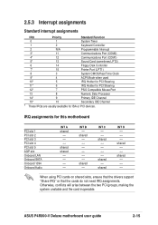
... motherboard PCI slot 1 PCI slot 2 PCI slot 3 PCI slot 4 PCI slot 5 AGP slot Onboard LAN Onboard SATA Onboard 1394 Onboard Audio INT A shared -- -- -- shared shared -- -- -- -- ASUS P4R800-V Deluxe motherboard user guide 2-15 IRQ assignments for ISA or PCI devices. INT B -- INT C -- -- shared --
... motherboard PCI slot 1 PCI slot 2 PCI slot 3 PCI slot 4 PCI slot 5 AGP slot Onboard LAN Onboard SATA Onboard 1394 Onboard Audio INT A shared -- -- -- shared shared -- -- -- -- ASUS P4R800-V Deluxe motherboard user guide 2-15 IRQ assignments for ISA or PCI devices. INT B -- INT C -- -- shared --

P4R800-V Deluxe User Manual
Page 39
ASUS WiFi-b™ Setup ASUS P4R800-V Deluxe motherboard user guide 2-17 The Wi-Fi slot conforms to the Institute of Electrical and Electronics Engineers (IEEE) 802.11b/g standard for wireless connectivity. P4R800-V DELUXE ® WIFI P4R800-V DELUXE WiFi Slot The PCI 5 slot and the Wi-Fi slot may not be used at the same time. 2.5.6 Wi-Fi slot The Wi-Fi slot supports the ASUS WiFi-b™ card and future IEEE 802.11g network interface card for wireless devices operating in the 2.4GHz frequency band.
ASUS WiFi-b™ Setup ASUS P4R800-V Deluxe motherboard user guide 2-17 The Wi-Fi slot conforms to the Institute of Electrical and Electronics Engineers (IEEE) 802.11b/g standard for wireless connectivity. P4R800-V DELUXE ® WIFI P4R800-V DELUXE WiFi Slot The PCI 5 slot and the Wi-Fi slot may not be used at the same time. 2.5.6 Wi-Fi slot The Wi-Fi slot supports the ASUS WiFi-b™ card and future IEEE 802.11g network interface card for wireless devices operating in the 2.4GHz frequency band.

P4R800-V Deluxe User Manual
Page 41
... USB device wake-up . • The total current consumed must NOT exceed the power supply capability (+5VSB) whether under normal condition or in sleep mode. ASUS P4R800-V Deluxe motherboard user guide 2-19 USB device wake-up the computer from S3 and S4 sleep modes (no power to wake up (3-pin USBPW56) Set this...
... USB device wake-up . • The total current consumed must NOT exceed the power supply capability (+5VSB) whether under normal condition or in sleep mode. ASUS P4R800-V Deluxe motherboard user guide 2-19 USB device wake-up the computer from S3 and S4 sleep modes (no power to wake up (3-pin USBPW56) Set this...

P4R800-V Deluxe User Manual
Page 43
... 2.0 ports 1 and 2. S-Video port. PS/2 keyboard port. Composite video port. After connecting one end to the motherboard, connect the other end to PIN 1. P4R800-V DELUXE Floppy Disk Drive Connector ASUS P4R800-V Deluxe motherboard user guide 2-21 Always connect ribbon cables with pin 5 plug). This port connects a VGA compatible monitor. 11. This port connects a television via...
... 2.0 ports 1 and 2. S-Video port. PS/2 keyboard port. Composite video port. After connecting one end to the motherboard, connect the other end to PIN 1. P4R800-V DELUXE Floppy Disk Drive Connector ASUS P4R800-V Deluxe motherboard user guide 2-21 Always connect ribbon cables with pin 5 plug). This port connects a VGA compatible monitor. 11. This port connects a television via...

P4R800-V Deluxe User Manual
Page 45
... UltraATA 133 hard disks. If you wish to this connector for RAID 0, RAID 1, or RAID 0+1 configuration. PIN 1 P4R800-V DELUXE PRI_RAID ® P4R800-V DELUXE RAID Connector NOTE: Orient the red markings (usually zigzag) on the RAID configuration. 4. ASUS P4R800-V Deluxe motherboard user guide 2-23 See Chapter 5 for details on RAID configuration. See Chapter 5 for details on the IDE...
... UltraATA 133 hard disks. If you wish to this connector for RAID 0, RAID 1, or RAID 0+1 configuration. PIN 1 P4R800-V DELUXE PRI_RAID ® P4R800-V DELUXE RAID Connector NOTE: Orient the red markings (usually zigzag) on the RAID configuration. 4. ASUS P4R800-V Deluxe motherboard user guide 2-23 See Chapter 5 for details on RAID configuration. See Chapter 5 for details on the IDE...

P4R800-V Deluxe User Manual
Page 47
The IEEE 1394 module is for the bundled S/PDIF module. TPA0GND TPB0+12V GND P4R800-V DELUXE ® P4R800-V DELUXE IEEE-1394 Connector IE1394_1 1 TPA0+ GND TPB0+ +12V NEVER connect a USB cable to this connector. Attach the 10-1 pin 1394 ... Connect one end of the S/PDIF module audio cable to the IEEE 1394 connector (red). ASUS P4R800-V Deluxe motherboard user guide 2-25 Doing so will damage the motherboard! 9. P4R800-V DELUXE ® SPDIF_OUT GND SPDIFOUT +5V P4R800-V DELUXE Digital Audio Connector The S/PDIF module that comes with the motherboard package has an optical and ...
The IEEE 1394 module is for the bundled S/PDIF module. TPA0GND TPB0+12V GND P4R800-V DELUXE ® P4R800-V DELUXE IEEE-1394 Connector IE1394_1 1 TPA0+ GND TPB0+ +12V NEVER connect a USB cable to this connector. Attach the 10-1 pin 1394 ... Connect one end of the S/PDIF module audio cable to the IEEE 1394 connector (red). ASUS P4R800-V Deluxe motherboard user guide 2-25 Doing so will damage the motherboard! 9. P4R800-V DELUXE ® SPDIF_OUT GND SPDIFOUT +5V P4R800-V DELUXE Digital Audio Connector The S/PDIF module that comes with the motherboard package has an optical and ...

P4R800-V Deluxe User Manual
Page 49
... Mbps connection speed. USB+5V USB_P6USB_P6+ GND NC USB+5V USB_P5USB_P5+ GND P4R800-V DELUXE ® USB56 1 P4R800-V DELUXE USB 2.0 Header 12. P4R800-V DELUXE ® MODEM Modem-In Ground Ground Modem-Out AUX (White) CD (Black) Right Audio Channel Ground Left Audio Channel P4R800-V DELUXE Internal Audio Connectors ASUS P4R800-V Deluxe motherboard user guide 2-27 USB headers (10-1 pin USB56 [blue]) If...
... Mbps connection speed. USB+5V USB_P6USB_P6+ GND NC USB+5V USB_P5USB_P5+ GND P4R800-V DELUXE ® USB56 1 P4R800-V DELUXE USB 2.0 Header 12. P4R800-V DELUXE ® MODEM Modem-In Ground Ground Modem-Out AUX (White) CD (Black) Right Audio Channel Ground Left Audio Channel P4R800-V DELUXE Internal Audio Connectors ASUS P4R800-V Deluxe motherboard user guide 2-27 USB headers (10-1 pin USB56 [blue]) If...

P4R800-V Deluxe User Manual
Page 51
... to the case-mounted speaker and allows you turn on the BIOS or OS settings. ASUS P4R800-V Deluxe motherboard user guide 2-29 Power LED Speaker Connector PLED+ PLED+5V Ground Ground Speaker P4R800-V DELUXE IDE_LED+ IDE_LED- PWR Ground Reset Ground ® P4R800-V DELUXE System Panel Connector IDE_LED Reset SW ATX Power Switch* * Requires an ATX power supply...
... to the case-mounted speaker and allows you turn on the BIOS or OS settings. ASUS P4R800-V Deluxe motherboard user guide 2-29 Power LED Speaker Connector PLED+ PLED+5V Ground Ground Speaker P4R800-V DELUXE IDE_LED+ IDE_LED- PWR Ground Reset Ground ® P4R800-V DELUXE System Panel Connector IDE_LED Reset SW ATX Power Switch* * Requires an ATX power supply...


