
Motherboard DIY Troubleshooting Guide
Page 11
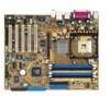
Installing the External ATI Graphics Card 7 Installing the External ATI Graphics Card AGP slot on Motherboard
Installing the External ATI Graphics Card 7 Installing the External ATI Graphics Card AGP slot on Motherboard

Motherboard DIY Troubleshooting Guide
Page 12
... to enable SURROUNDVIEW™. If necessary, consult your computer's manual for help in place, and then replace the computer cover. 5 Connect one display to the motherboard's internal graphics connector A , and then connect the other two displays to the external graphics card monitor connectors B and C . A BC Monitor Connectors on back of computer...
... to enable SURROUNDVIEW™. If necessary, consult your computer's manual for help in place, and then replace the computer cover. 5 Connect one display to the motherboard's internal graphics connector A , and then connect the other two displays to the external graphics card monitor connectors B and C . A BC Monitor Connectors on back of computer...

Motherboard DIY Troubleshooting Guide
Page 13
Enabling SURROUNDVIEW™ 9 Enabling SURROUNDVIEW™ Enable SURROUNDVIEW using the system BIOS settings. • The motherboard manufacturer must have at least 256MB of RAM to use the + or - The Advanced Chipset Features screen appears. 3 Use the arrow ...Setup. key to set it to enable / disable internal i graphics when external graphics cards are used. • Implementation may vary, depending upon the motherboard manufacturer. The Integrated Peripherals screen appears. 6 Use the arrow keys to navigate to Init Display First, and then set it to AGP. When restarting...
Enabling SURROUNDVIEW™ 9 Enabling SURROUNDVIEW™ Enable SURROUNDVIEW using the system BIOS settings. • The motherboard manufacturer must have at least 256MB of RAM to use the + or - The Advanced Chipset Features screen appears. 3 Use the arrow ...Setup. key to set it to enable / disable internal i graphics when external graphics cards are used. • Implementation may vary, depending upon the motherboard manufacturer. The Integrated Peripherals screen appears. 6 Use the arrow keys to navigate to Init Display First, and then set it to AGP. When restarting...

Motherboard DIY Troubleshooting Guide
Page 14
...] Feature [Status] Feature [Status] Feature [Status] Feature [Status] Feature [Status] Item Help BIOS Settings - Integrated Peripherals Screen These screens may look different, depending upon the motherboard manufacturer. 10 Enabling SURROUNDVIEW™ 7 Use the arrow keys to navigate to SURROUNDVIEW, press Enter, use the arrow keys to select Enable, and then press...
...] Feature [Status] Feature [Status] Feature [Status] Feature [Status] Feature [Status] Item Help BIOS Settings - Integrated Peripherals Screen These screens may look different, depending upon the motherboard manufacturer. 10 Enabling SURROUNDVIEW™ 7 Use the arrow keys to navigate to SURROUNDVIEW, press Enter, use the arrow keys to select Enable, and then press...

P4R800-V Deluxe User Manual
Page 1
Motherboard P4R800-V Deluxe User Guide
Motherboard P4R800-V Deluxe User Guide

P4R800-V Deluxe User Manual
Page 3
Features Contents Notices vi Safety information vii About this guide viii P4R800-V Deluxe specification summary x Chapter 1: Product introduction 1.1 Welcome 1 1.2 Package contents 1 1.3 Special features 2 1.3.1 Product highlights 2 1.3.2 ASUS unique features 4 Chapter 2: Hardware information 2.1 Before you proceed 2-1 2.2 Motherboard layout 2-2 2.2.1 Major components 2-3 2.2.2 Placement direction 2-4 2.2.3 Screw holes 2-4 2.3 Central Processing Unit (CPU 2-5 2.3.1 Overview 2-5 2.3.2 Installing the CPU 2-6 2.3.3 Installing the heatsink and fan...
Features Contents Notices vi Safety information vii About this guide viii P4R800-V Deluxe specification summary x Chapter 1: Product introduction 1.1 Welcome 1 1.2 Package contents 1 1.3 Special features 2 1.3.1 Product highlights 2 1.3.2 ASUS unique features 4 Chapter 2: Hardware information 2.1 Before you proceed 2-1 2.2 Motherboard layout 2-2 2.2.1 Major components 2-3 2.2.2 Placement direction 2-4 2.2.3 Screw holes 2-4 2.3 Central Processing Unit (CPU 2-5 2.3.1 Overview 2-5 2.3.2 Installing the CPU 2-6 2.3.3 Installing the heatsink and fan...

P4R800-V Deluxe User Manual
Page 7
...service technician or your dealer immediately. • To avoid short circuits, keep paper clips, screws, and staples away from the motherboard, ensure that all power cables are unplugged. • Seek professional assistance before the signal cables are not damaged. vii Safety ...set to fix it , carefully read all cables are correctly connected and the power cables are connected. Operation safety • Before installing the motherboard and adding devices on a stable surface. • If you add a device. • Before connecting or removing signal cables from connectors, ...
...service technician or your dealer immediately. • To avoid short circuits, keep paper clips, screws, and staples away from the motherboard, ensure that all power cables are unplugged. • Seek professional assistance before the signal cables are not damaged. vii Safety ...set to fix it , carefully read all cables are correctly connected and the power cables are connected. Operation safety • Before installing the motherboard and adding devices on a stable surface. • If you add a device. • Before connecting or removing signal cables from connectors, ...

P4R800-V Deluxe User Manual
Page 8
...; Quick Reference Card viii It includes description of the switches, jumpers, and connectors on the motherboard. • Chapter 3: Powering up This chapter describes the power up sequence and gives information on the BIOS beep codes and the ASUS Post Reporter™ feature. • Chapter 4: BIOS setup This chapter tells how to perform...
...; Quick Reference Card viii It includes description of the switches, jumpers, and connectors on the motherboard. • Chapter 3: Powering up This chapter describes the power up sequence and gives information on the BIOS beep codes and the ASUS Post Reporter™ feature. • Chapter 4: BIOS setup This chapter tells how to perform...

P4R800-V Deluxe User Manual
Page 13
Chapter 1 This chapter describes the features of the motherboard and the new technology it supports. It includes brief descriptions of the special attributes of the motherboard. Product introduction
Chapter 1 This chapter describes the features of the motherboard and the new technology it supports. It includes brief descriptions of the special attributes of the motherboard. Product introduction

P4R800-V Deluxe User Manual
Page 14
Chapter summary 1.1 Welcome 1-1 1.2 Package contents 1-1 1.3 Special features 1-2 ASUS P4R800-V Deluxe motherboard
Chapter summary 1.1 Welcome 1-1 1.2 Package contents 1-1 1.3 Special features 1-2 ASUS P4R800-V Deluxe motherboard

P4R800-V Deluxe User Manual
Page 15
...missing, contact your P4R800-V Deluxe package for the following items. ASUS P4R800-V Deluxe motherboard ASUS P4R800-V series support CD 2 x SATA cable 2 x SATA power cable 1 x 80-conductor ribbon cables for UltraDMA IDE drives 9-pin COM cable Ribbon cable for buying the ASUS P4R800-V Deluxe motherboard! ASUS P4R800-V Deluxe motherboard user guide 1-1... (Retail boxes only.) Jumpers and connectors stickers (Retail boxes only.) If any of ASUS quality motherboards! Thank you start installing the motherboard, and hardware devices on it another standout in your package with the list below....
...missing, contact your P4R800-V Deluxe package for the following items. ASUS P4R800-V Deluxe motherboard ASUS P4R800-V series support CD 2 x SATA cable 2 x SATA power cable 1 x 80-conductor ribbon cables for UltraDMA IDE drives 9-pin COM cable Ribbon cable for buying the ASUS P4R800-V Deluxe motherboard! ASUS P4R800-V Deluxe motherboard user guide 1-1... (Retail boxes only.) Jumpers and connectors stickers (Retail boxes only.) If any of ASUS quality motherboards! Thank you start installing the motherboard, and hardware devices on it another standout in your package with the list below....

P4R800-V Deluxe User Manual
Page 16
... or a dual memory architecture for up to 266MB/s. See page 2-5. 1.3 Special features 1.3.1 Product highlights 800MHz FSB CPU support The P4R800-V Deluxe comes with a 478-pin surface mount, Zero Insertion Force (ZIF) socket for the Intel® Pentium® 4 Northwood/Willamette ...interface connects the IXP 150 with 512/256KB L2 cache on 0.13 micron process. This motherboard supports 800/533/400 MHz system front side bus that supports AGP 8X specification. The P4R800-V Deluxe also supports the Intel® Hyper-Threading Technology and the next-generation Intel® Prescott ...
... or a dual memory architecture for up to 266MB/s. See page 2-5. 1.3 Special features 1.3.1 Product highlights 800MHz FSB CPU support The P4R800-V Deluxe comes with a 478-pin surface mount, Zero Insertion Force (ZIF) socket for the Intel® Pentium® 4 Northwood/Willamette ...interface connects the IXP 150 with 512/256KB L2 cache on 0.13 micron process. This motherboard supports 800/533/400 MHz system front side bus that supports AGP 8X specification. The P4R800-V Deluxe also supports the Intel® Hyper-Threading Technology and the next-generation Intel® Prescott ...

P4R800-V Deluxe User Manual
Page 17
...32bpp and implements innovative ATI technologies including Pixel Tapestry™ II, Smartshader™, Smoothvision™, and Video Immersion™ II. ASUS P4R800-V Deluxe motherboard user guide 1-3 Ai NET solution Ai NET supports the onboard Marvell® 88E001 Gigabit LAN controller for business professionals, audiophiles, ... LAN controller comes with lower pin count, reduced voltage requirement, up to 100 meters to 150 MB/s data transfer rate. This motherboard also comes with a S/PDIF module to powerful sound systems. See page 2-25. See page 2-23. See page 5-7. See ...
...32bpp and implements innovative ATI technologies including Pixel Tapestry™ II, Smartshader™, Smoothvision™, and Video Immersion™ II. ASUS P4R800-V Deluxe motherboard user guide 1-3 Ai NET solution Ai NET supports the onboard Marvell® 88E001 Gigabit LAN controller for business professionals, audiophiles, ... LAN controller comes with lower pin count, reduced voltage requirement, up to 100 meters to 150 MB/s data transfer rate. This motherboard also comes with a S/PDIF module to powerful sound systems. See page 2-25. See page 2-23. See page 5-7. See ...

P4R800-V Deluxe User Manual
Page 18
USB 2.0 technology The motherboard implements the Universal Serial Bus (USB) 2.0 specification, dramatically increasing the connection speed from a bootable floppy disk, when the BIOS codes and data are corrupted. USB 2.0 is a combination of three ASUS intelligent solutions: CrachFree BIOS2, Q-Fan and ...page 4-4. See page 4-28. 1-4 Chapter 1: Product introduction See page 2-25. 1.3.2 ASUS unique features Ai BIOS The Ai Bios is backward compatible with USB 1.1. Q-Fan technology The ASUS Q-Fan technology smartly adjusts the fan speeds according to the system loading to buy a replacement...
USB 2.0 technology The motherboard implements the Universal Serial Bus (USB) 2.0 specification, dramatically increasing the connection speed from a bootable floppy disk, when the BIOS codes and data are corrupted. USB 2.0 is a combination of three ASUS intelligent solutions: CrachFree BIOS2, Q-Fan and ...page 4-4. See page 4-28. 1-4 Chapter 1: Product introduction See page 2-25. 1.3.2 ASUS unique features Ai BIOS The Ai Bios is backward compatible with USB 1.1. Q-Fan technology The ASUS Q-Fan technology smartly adjusts the fan speeds according to the system loading to buy a replacement...

P4R800-V Deluxe User Manual
Page 19
...Japanese. eliminates the need to overclocking. ASUS P4R800-V Deluxe motherboard user guide 1-5 Wi-Fi slot The ASUS Wi-Fi slot is based on the IEEE 802.11b/g wireless standard and is automatically installed when you to select the language of boot errors, if any. The ASUS WiFi-b™ add-on card for... future upgrades. feature of the motherboard BIOS allows automatic re-setting to the BIOS default settings in the motherboard allows you to personalize and add style to save the extra cost...
...Japanese. eliminates the need to overclocking. ASUS P4R800-V Deluxe motherboard user guide 1-5 Wi-Fi slot The ASUS Wi-Fi slot is based on the IEEE 802.11b/g wireless standard and is automatically installed when you to select the language of boot errors, if any. The ASUS WiFi-b™ add-on card for... future upgrades. feature of the motherboard BIOS allows automatic re-setting to the BIOS default settings in the motherboard allows you to personalize and add style to save the extra cost...

P4R800-V Deluxe User Manual
Page 21
Chapter 2 This chapter lists the hardware setup procedures that you have to perform when installing system components. Hardware information It includes description of the switches, jumpers, and connectors on the motherboard.
Chapter 2 This chapter lists the hardware setup procedures that you have to perform when installing system components. Hardware information It includes description of the switches, jumpers, and connectors on the motherboard.

P4R800-V Deluxe User Manual
Page 22
Chapter summary 2.1 Before you proceed 2-1 2.2 Motherboard layout 2-2 2.3 Central Processing Unit (CPU 2-5 2.4 System memory 2-10 2.5 Expansion slots 2-14 2.6 Jumpers 2-18 2.7 Connectors 2-20 ASUS P4R800-V Deluxe motherboard
Chapter summary 2.1 Before you proceed 2-1 2.2 Motherboard layout 2-2 2.3 Central Processing Unit (CPU 2-5 2.4 System memory 2-10 2.5 Expansion slots 2-14 2.6 Jumpers 2-18 2.7 Connectors 2-20 ASUS P4R800-V Deluxe motherboard

P4R800-V Deluxe User Manual
Page 23
... handling components to avoid damaging them due to static electricity. • Hold components by the edges to the motherboard, peripherals, and/or components. P4R800-V DELUXE SB_PWR ® ON Standby Power P4R800-V DELUXE Onboard LED OFF Powered Off ASUS P4R800-V Deluxe motherboard user guide 2-1 Failure to do so may cause severe damage to avoid touching the ICs on them. •...
... handling components to avoid damaging them due to static electricity. • Hold components by the edges to the motherboard, peripherals, and/or components. P4R800-V DELUXE SB_PWR ® ON Standby Power P4R800-V DELUXE Onboard LED OFF Powered Off ASUS P4R800-V Deluxe motherboard user guide 2-1 Failure to do so may cause severe damage to avoid touching the ICs on them. •...

P4R800-V Deluxe User Manual
Page 25
... 2.0 connector 2-27 4-pin CD/Auxilliary/Modem connectors 2-27 3-pin Chassis/CPU/Power connectors 2-28 10-1 pin Front Audio connector 2-28 10-1 pin Panel connector 2-29 ASUS P4R800-V Deluxe motherboard user guide 2-3
... 2.0 connector 2-27 4-pin CD/Auxilliary/Modem connectors 2-27 3-pin Chassis/CPU/Power connectors 2-28 10-1 pin Front Audio connector 2-28 10-1 pin Panel connector 2-29 ASUS P4R800-V Deluxe motherboard user guide 2-3

P4R800-V Deluxe User Manual
Page 26
The edge with external ports goes to the chassis. Place this side towards the rear of the chassis as indicated in the correct orientation. Do not overtighten the screws! Doing so may damage the motherboard. 2.2.2 Placement direction When installing the motherboard, make sure that you place it into the chassis in the image below. 2.2.3 Screw holes Place nine (9) screws into the holes indicated by circles to secure the motherboard to the rear part of the chassis 2-4 Chapter 2: Hardware information
The edge with external ports goes to the chassis. Place this side towards the rear of the chassis as indicated in the correct orientation. Do not overtighten the screws! Doing so may damage the motherboard. 2.2.2 Placement direction When installing the motherboard, make sure that you place it into the chassis in the image below. 2.2.3 Screw holes Place nine (9) screws into the holes indicated by circles to secure the motherboard to the rear part of the chassis 2-4 Chapter 2: Hardware information


