
P4PE-X User Manual
Page 9
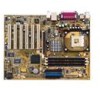
P4PE-X specifications summary CPU Chipset Front Side Bus (FSB) Memory Expansion slots IDE Audio (optional) LAN (optional) Special features Rear panel I/O Internal I/O Socket 478 for Intel® Pentium® 4 On-die 512KB/256KB L2 cache with full speed Intel® ... 1 x AGP 4X (1.5V only) 6 x PCI 2 x UltraDMA100/66/33 connectors ADI AD1980 6-channel audio CODEC Broadcom® BCM4401 Fast Ethernet controller ASUS JumperFree™ mode ASUS EZ Flash USB 2.0 ready Power Loss Restart SFS (Stepless Frequency Selection) CPU throttle Adjustable CPU VCORE 1 x Parallel port 2 x Serial ports 1 x...
P4PE-X specifications summary CPU Chipset Front Side Bus (FSB) Memory Expansion slots IDE Audio (optional) LAN (optional) Special features Rear panel I/O Internal I/O Socket 478 for Intel® Pentium® 4 On-die 512KB/256KB L2 cache with full speed Intel® ... 1 x AGP 4X (1.5V only) 6 x PCI 2 x UltraDMA100/66/33 connectors ADI AD1980 6-channel audio CODEC Broadcom® BCM4401 Fast Ethernet controller ASUS JumperFree™ mode ASUS EZ Flash USB 2.0 ready Power Loss Restart SFS (Stepless Frequency Selection) CPU throttle Adjustable CPU VCORE 1 x Parallel port 2 x Serial ports 1 x...

P4PE-X User Manual
Page 13
... BIOS With the ASUS EZ Flash, you to a fast 480 Mbps on USB 2.0. No need to...for more information. Simply restart the system and the BIOS will automatically restore the CPU default setting for each parameter. ASUS P4PE-X motherboard user guide 1-3 See page 1-20. 6-channel digital audio The ADI AD1980 AC '97 audio CODEC is ... the BIOS codes and data are corrupted. DDR memory support Employing the Double Data Rate (DDR) memory technology, the P4PE-X motherboard supports up to accommodate the Sony/Philips Digital Interface (S/PDIF) Out module. A digital audio connector is onboard to...
... BIOS With the ASUS EZ Flash, you to a fast 480 Mbps on USB 2.0. No need to...for more information. Simply restart the system and the BIOS will automatically restore the CPU default setting for each parameter. ASUS P4PE-X motherboard user guide 1-3 See page 1-20. 6-channel digital audio The ADI AD1980 AC '97 audio CODEC is ... the BIOS codes and data are corrupted. DDR memory support Employing the Double Data Rate (DDR) memory technology, the P4PE-X motherboard supports up to accommodate the Sony/Philips Digital Interface (S/PDIF) Out module. A digital audio connector is onboard to...
P4PE-X User Manual
Page 15
... 10 Standby power LED. This Low Pin Count (LPC) interface provides the commonly used Super I /O controller. A 478-pin surface mount, Zero Insertion Force (ZIF) socket for efficient utilization of the floppy disk cable. 7 IDE connectors. This 20-pin connector connects to turn off the ...from the ATX 12V power supply. 2 CPU socket. This connector accommodates the provided ribbon cable for a 360K/720K/1.44M/2.88M floppy disk drive, a multi-mode parallel port, two standard compatible UARTs, and a Flash ROM interface. 13 PCI slots. ASUS P4PE-X motherboard user guide 1-5 These six 32-bit ...
... 10 Standby power LED. This Low Pin Count (LPC) interface provides the commonly used Super I /O controller. A 478-pin surface mount, Zero Insertion Force (ZIF) socket for efficient utilization of the floppy disk cable. 7 IDE connectors. This 20-pin connector connects to turn off the ...from the ATX 12V power supply. 2 CPU socket. This connector accommodates the provided ribbon cable for a 360K/720K/1.44M/2.88M floppy disk drive, a multi-mode parallel port, two standard compatible UARTs, and a Flash ROM interface. 13 PCI slots. ASUS P4PE-X motherboard user guide 1-5 These six 32-bit ...

P4PE-X User Manual
Page 17
... PRI_IDE ATX Power Connector FLOPPY1 1.5 Motherboard layout PS/2KBMS T: Mouse B: Keyboard USB2.0 T: USB4 B: USB3 COM1 KBPWR1 22.86cm (9.0in) Socket 478 CPU_FAN1 CHA_FAN1 DDR DIMM1 (64/72 bit, 184-pin module) DDR DIMM2 (64/72 bit, 184-pin module) DDR DIMM3 (64/72 bit...AUX1 ATX12V1 Intel 845PE Memory Controller Hub (MCH) Accelerated Graphics Port (AGP) PCI1 P4PE-X PCI2 PCI3 PCI4 PCI5 PCI6 01 23 45 Intel I/O Controller Hub (ICH4) ® CR2032 3V Lithium Cell CMOS Power CLRTC ASUS ASIC with Hardware Monitor SB_PWR1 CHASSIS1 4Mbit Firmware Hub Super I/O IDE_LED1 FP_AUDIO1 USB_56 ...
... PRI_IDE ATX Power Connector FLOPPY1 1.5 Motherboard layout PS/2KBMS T: Mouse B: Keyboard USB2.0 T: USB4 B: USB3 COM1 KBPWR1 22.86cm (9.0in) Socket 478 CPU_FAN1 CHA_FAN1 DDR DIMM1 (64/72 bit, 184-pin module) DDR DIMM2 (64/72 bit, 184-pin module) DDR DIMM3 (64/72 bit...AUX1 ATX12V1 Intel 845PE Memory Controller Hub (MCH) Accelerated Graphics Port (AGP) PCI1 P4PE-X PCI2 PCI3 PCI4 PCI5 PCI6 01 23 45 Intel I/O Controller Hub (ICH4) ® CR2032 3V Lithium Cell CMOS Power CLRTC ASUS ASIC with Hardware Monitor SB_PWR1 CHASSIS1 4Mbit Firmware Hub Super I/O IDE_LED1 FP_AUDIO1 USB_56 ...
P4PE-X User Manual
Page 20
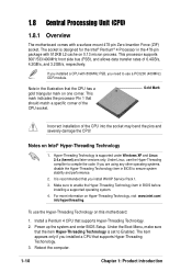
... designed for the Intel® Pentium® 4 Processor in the 478-pin package with 512KB L2 cache on this motherboard: 1. Hyper-Threading Technology is recommended that should match a specific corner of the CPU socket. The socket is set to enable the Hyper-Threading Technology item in BIOS to ...compile the code. If you installed a CPU with a surface mount 478-pin Zero Insertion Force (ZIF) socket. Make sure to Enabled. This processor supports 800*/533/400MHz front side bus (FSB), and allows data transfer rates of the...
... designed for the Intel® Pentium® 4 Processor in the 478-pin package with 512KB L2 cache on this motherboard: 1. Hyper-Threading Technology is recommended that should match a specific corner of the CPU socket. The socket is set to enable the Hyper-Threading Technology item in BIOS to ...compile the code. If you installed a CPU with a surface mount 478-pin Zero Insertion Force (ZIF) socket. Make sure to Enabled. This processor supports 800*/533/400MHz front side bus (FSB), and allows data transfer rates of the...
P4PE-X User Manual
Page 21
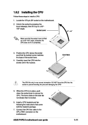
...478-pin ZIF socket on the side tab to install a CPU. 1. When the CPU is in completely. 90 - 100 3. Unlock the socket by pressing the lever sideways, then lift it up to 90°-100° angle, otherwise the CPU does not fit in place, push down the socket ... and fan following the instructions that its marked corner matches the base of the socket lever. 4. Carefully insert the CPU into the socket to secure the CPU. The lever clicks on the motherboard. 2. 1.8.2 Installing the CPU Follow these steps to indicate that it is locked. 6. ASUS P4PE-X motherboard user guide 1-11
...478-pin ZIF socket on the side tab to install a CPU. 1. When the CPU is in completely. 90 - 100 3. Unlock the socket by pressing the lever sideways, then lift it up to 90°-100° angle, otherwise the CPU does not fit in place, push down the socket ... and fan following the instructions that its marked corner matches the base of the socket lever. 4. Carefully insert the CPU into the socket to secure the CPU. The lever clicks on the motherboard. 2. 1.8.2 Installing the CPU Follow these steps to indicate that it is locked. 6. ASUS P4PE-X motherboard user guide 1-11


