P4BGL-VM User Manual
Page 4
... 2.8 Connectors 2-20 Chapter 3: Powering up 3.1 Starting up for the first time 3-1 3.2 Powering off the computer 3-2 Chapter 4: BIOS setup 4.1 Managing and updating your BIOS 4-1 4.1.1 Using ASUS EZ Flash to update the BIOS 4-1 4.1.2 Using AFLASH to update the BIOS 4-3 4.2 BIOS Setup program 4-7 4.2.1 BIOS menu bar 4-8 4.2.2 Legend bar 4-8 4.3 Main Menu 4-10 4.3.1 Primary and Secondary Master/Slave 4-12 4.3.2 Keyboard Features 4-16...
... 2.8 Connectors 2-20 Chapter 3: Powering up 3.1 Starting up for the first time 3-1 3.2 Powering off the computer 3-2 Chapter 4: BIOS setup 4.1 Managing and updating your BIOS 4-1 4.1.1 Using ASUS EZ Flash to update the BIOS 4-1 4.1.2 Using AFLASH to update the BIOS 4-3 4.2 BIOS Setup program 4-7 4.2.1 BIOS menu bar 4-8 4.2.2 Legend bar 4-8 4.3 Main Menu 4-10 4.3.1 Primary and Secondary Master/Slave 4-12 4.3.2 Keyboard Features 4-16...
P4BGL-VM User Manual
Page 8
...the P4BGL-VM motherboard. Detailed descriptions of the BIOS parameters are also provided. • Chapter 5: Software support This chapter describes the contents of the support CD that comes with the motherboard package. • Glossary This part defines the technical terms that you need when installing the ASUS P4BGL-VM motherboard....connectors on the motherboard. • Chapter 3: Powering up This chapter describes the power up sequence and gives information on the BIOS beep codes. • Chapter 4: BIOS setup This chapter tells how to perform when installing system components. viii
...the P4BGL-VM motherboard. Detailed descriptions of the BIOS parameters are also provided. • Chapter 5: Software support This chapter describes the contents of the support CD that comes with the motherboard package. • Glossary This part defines the technical terms that you need when installing the ASUS P4BGL-VM motherboard....connectors on the motherboard. • Chapter 3: Powering up This chapter describes the power up sequence and gives information on the BIOS beep codes. • Chapter 4: BIOS setup This chapter tells how to perform when installing system components. viii
P4BGL-VM User Manual
Page 17
...off The system fans power off automatically when the system is monitored by the ASUS ASIC through the ASUS ASIC. The system fan rotations per minute (RPM) is retained in BIOS using the ASUS JumperFree™ solution. The system voltage levels are monitored to soft-off mode... more than 4 seconds puts the system to sleep mode or to ensure stable supply of the BIOS setting. A chassis intrusion event is monitored for timely failure detection. ASUS P4BGL-VM motherboard user guide 1-3 This feature reduces both power consumption and system noise. Concurrent PCI This feature...
...off The system fans power off automatically when the system is monitored by the ASUS ASIC through the ASUS ASIC. The system fan rotations per minute (RPM) is retained in BIOS using the ASUS JumperFree™ solution. The system voltage levels are monitored to soft-off mode... more than 4 seconds puts the system to sleep mode or to ensure stable supply of the BIOS setting. A chassis intrusion event is monitored for timely failure detection. ASUS P4BGL-VM motherboard user guide 1-3 This feature reduces both power consumption and system noise. Concurrent PCI This feature...
P4BGL-VM User Manual
Page 21
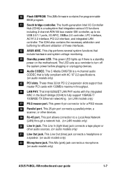
This 2Mb firmware contains the programmable BIOS program. 11 South bridge controller. This green LED lights up to a Local... functions including 2-channel ATA/100 bus master IDE controller, up if there is for efficient utilization of these interfaces. 12 ASUS ASIC. This Mic (pink) jack connects a microphone. (on audio models only) 21 Line Out jack. 10 Flash... connects a parallel printer, a scanner, or other audio sources. (on audio models only) ASUS P4BGL-VM motherboard user guide 1-7 This green 6-pin connector is a standby power on LAN models only) 17 PS/2 mouse port.
This 2Mb firmware contains the programmable BIOS program. 11 South bridge controller. This green LED lights up to a Local... functions including 2-channel ATA/100 bus master IDE controller, up if there is for efficient utilization of these interfaces. 12 ASUS ASIC. This Mic (pink) jack connects a microphone. (on audio models only) 21 Line Out jack. 10 Flash... connects a parallel printer, a scanner, or other audio sources. (on audio models only) ASUS P4BGL-VM motherboard user guide 1-7 This green 6-pin connector is a standby power on LAN models only) 17 PS/2 mouse port.
P4BGL-VM User Manual
Page 37
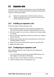
...and make the necessary hardware settings for later use . Align the card connector with it by adjusting the software settings. 1. Turn on BIOS setup. 2. Assign an IRQ to the tables on the slot. 5. Remove the bracket opposite the slot that came with the slot and...expansion cards. The motherboard has three PCI slots. Before installing the expansion card, read the documentation that you intend to use . 4. ASUS P4BGL-VM motherboard user guide 2-13 The following sub-sections describe the slots and the expansion cards that they support. Secure the card to install...
...and make the necessary hardware settings for later use . Align the card connector with it by adjusting the software settings. 1. Turn on BIOS setup. 2. Assign an IRQ to the tables on the slot. 5. Remove the bracket opposite the slot that came with the slot and...expansion cards. The motherboard has three PCI slots. Before installing the expansion card, read the documentation that you intend to use . 4. ASUS P4BGL-VM motherboard user guide 2-13 The following sub-sections describe the slots and the expansion cards that they support. Secure the card to install...
P4BGL-VM User Manual
Page 40
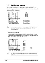
... to enable or disable the JumperFree™ mode. The illustration below shows all the switches in the ON position. ® SW1 ON 12345 ON OFF P4BGL-VM P4BGL-VM DIP Switches 1.Frequency Selection 2.Frequency Selection 3.Frequency Selection 4.Frequency Selection 5.Frequency Selection The J6 jumper must be set to pins 2-3 (jumper mode) if you to..., setting the switches does not produce any effect. 1. The white block represents the switch position. 2.7 Switches and jumpers The motherboard frequency is adjusted through the BIOS setup instead of using the DIP switches.
... to enable or disable the JumperFree™ mode. The illustration below shows all the switches in the ON position. ® SW1 ON 12345 ON OFF P4BGL-VM P4BGL-VM DIP Switches 1.Frequency Selection 2.Frequency Selection 3.Frequency Selection 4.Frequency Selection 5.Frequency Selection The J6 jumper must be set to pins 2-3 (jumper mode) if you to..., setting the switches does not produce any effect. 1. The white block represents the switch position. 2.7 Switches and jumpers The motherboard frequency is adjusted through the BIOS setup instead of using the DIP switches.
P4BGL-VM User Manual
Page 41
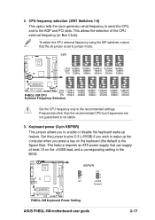
... wake-up the computer when you press a key on the +5VSB lead, and a corresponding setting in the BIOS. ® P4BGL-VM KBPWR 1 2 +5V 2 3 +5VSB (Default) P4BGL-VM Keyboard Power Setting ASUS P4BGL-VM motherboard user guide 2-17 This feature requires an ATX power supply that the J6 jumper is the Space Bar). ... 35MHz 35MHz 36MHz ON 12345 ON 12345 ON 12345 ON 12345 ON 12345 ON 12345 P4BGL-VM CPU 111MHz 114MHz 120MHz 125MHz 133MHz 135MHz AGP 74MHz 76MHz 60MHz 62MHz 66MHz 67MHz P4BGL-VM CPU PCI 37MHz 38MHz 30MHz 31MHz 33MHz 33MHz External Frequency Selection Set the CPU frequency ...
... wake-up the computer when you press a key on the +5VSB lead, and a corresponding setting in the BIOS. ® P4BGL-VM KBPWR 1 2 +5V 2 3 +5VSB (Default) P4BGL-VM Keyboard Power Setting ASUS P4BGL-VM motherboard user guide 2-17 This feature requires an ATX power supply that the J6 jumper is the Space Bar). ... 35MHz 35MHz 36MHz ON 12345 ON 12345 ON 12345 ON 12345 ON 12345 ON 12345 P4BGL-VM CPU 111MHz 114MHz 120MHz 125MHz 133MHz 135MHz AGP 74MHz 76MHz 60MHz 62MHz 66MHz 67MHz P4BGL-VM CPU PCI 37MHz 38MHz 30MHz 31MHz 33MHz 33MHz External Frequency Selection Set the CPU frequency ...
P4BGL-VM User Manual
Page 45
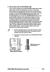
BIOS supports specific device bootup. PIN 1 ASUS P4BGL-VM motherboard user guide 2-21 You may configure two hard disks to the UltraDMA/100/66 master device. This prevents incorrect orientation when you connect non-...-1 pin PRI_IDE/SEC_IDE) This connector supports the provided UltraDMA/100/66 IDE hard disk ribbon cable. Pin 20 on each IDE connector is intentional. ® P4BGL-VM P4BGL-VM IDE Connectors SEC_IDE PRI_IDE NOTE: Orient the red markings (usually zigzag) on the UltraDMA cable connector. The hole near the blue connector on the UltraDMA...
BIOS supports specific device bootup. PIN 1 ASUS P4BGL-VM motherboard user guide 2-21 You may configure two hard disks to the UltraDMA/100/66 master device. This prevents incorrect orientation when you connect non-...-1 pin PRI_IDE/SEC_IDE) This connector supports the provided UltraDMA/100/66 IDE hard disk ribbon cable. Pin 20 on each IDE connector is intentional. ® P4BGL-VM P4BGL-VM IDE Connectors SEC_IDE PRI_IDE NOTE: Orient the red markings (usually zigzag) on the UltraDMA cable connector. The hole near the blue connector on the UltraDMA...
P4BGL-VM User Manual
Page 49
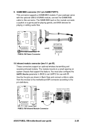
...Use the five pins as shown in BIOS to the pin definitions. ® P4BGL-VM SIR CIR IRTX CIR+5V GND CIRRX IRRX GND +5V IRAX Standard Infrared (SIR) Front View Back View IRTX +5V GND (NC) IRRX P4BGL-VM Infrared Module Connector ASUS P4BGL-VM motherboard user guide 2-25 The GAME/...motherboard SIR connector according to set UART2 for playing or editing audio files. ® GND J1B2 J1CY GND GND J1CX J1B1 GND P4BGL-VM 8 1 GAME 16 9 P4BGL-VM Game Connector MIDI_IN J2B2 J2CY MIDI_OUT J2CX J2B1 GND 10. GAME/MIDI connector (16-1 pin GAME PORT1) This connector supports a...
...Use the five pins as shown in BIOS to the pin definitions. ® P4BGL-VM SIR CIR IRTX CIR+5V GND CIRRX IRRX GND +5V IRAX Standard Infrared (SIR) Front View Back View IRTX +5V GND (NC) IRRX P4BGL-VM Infrared Module Connector ASUS P4BGL-VM motherboard user guide 2-25 The GAME/...motherboard SIR connector according to set UART2 for playing or editing audio files. ® GND J1B2 J1CY GND GND J1CX J1B1 GND P4BGL-VM 8 1 GAME 16 9 P4BGL-VM Game Connector MIDI_IN J2B2 J2CY MIDI_OUT J2CX J2B1 GND 10. GAME/MIDI connector (16-1 pin GAME PORT1) This connector supports a...
P4BGL-VM User Manual
Page 53
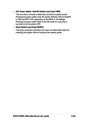
ASUS P4BGL-VM motherboard user guide 2-29 Pressing the power switch turns the system between ON and SLEEP, or ON and SOFT OFF, depending on the BIOS or OS settings. Pressing the power switch while in the ON mode for more than 4 seconds turns the system OFF. • Reset Switch Lead (2-pin RESET) This 2-pin connector connects to the case-mounted reset switch for rebooting the system without turning off the system power. • ATX Power Switch / Soft-Off Switch Lead (2-pin PWR) This connector connects a switch that controls the system power.
ASUS P4BGL-VM motherboard user guide 2-29 Pressing the power switch turns the system between ON and SLEEP, or ON and SOFT OFF, depending on the BIOS or OS settings. Pressing the power switch while in the ON mode for more than 4 seconds turns the system OFF. • Reset Switch Lead (2-pin RESET) This 2-pin connector connects to the case-mounted reset switch for rebooting the system without turning off the system power. • ATX Power Switch / Soft-Off Switch Lead (2-pin PWR) This connector connects a switch that controls the system power.
P4BGL-VM User Manual
Page 55
Chapter 3 This chapter describes the power up Powering up sequence and gives information on the BIOS beep codes.
Chapter 3 This chapter describes the power up Powering up sequence and gives information on the BIOS beep codes.
P4BGL-VM User Manual
Page 57
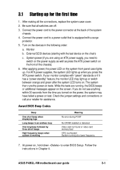
...settings and connections or call your monitor complies with the last device on the power, the system may light up . System running , the BIOS beeps or additional messages appear on . After applying power, the power LED on the system front panel case lights up or switch between ... order: a. 3.1 Starting up for assistance. The system then runs the power-on , hold down to the power connector at a lower frequency 7. ASUS P4BGL-VM motherboard user guide 3-1 Be sure that is working Meaning No error during POST No DRAM installed or detected Video card not found or video card...
...settings and connections or call your monitor complies with the last device on the power, the system may light up . System running , the BIOS beeps or additional messages appear on . After applying power, the power LED on the system front panel case lights up or switch between ... order: a. 3.1 Starting up for assistance. The system then runs the power-on , hold down to the power connector at a lower frequency 7. ASUS P4BGL-VM motherboard user guide 3-1 Be sure that is working Meaning No error during POST No DRAM installed or detected Video card not found or video card...
P4BGL-VM User Manual
Page 59
Chapter 4 This chapter tells how to change system settings through the BIOS Setup menus. Detailed descriptions of the BIOS parameters are also provided. BIOS setup
Chapter 4 This chapter tells how to change system settings through the BIOS Setup menus. Detailed descriptions of the BIOS parameters are also provided. BIOS setup
P4BGL-VM User Manual
Page 60
Chapter summary 4.1 Managing and updating your BIOS 1 4.2 BIOS Setup program 7 4.3 Main Menu 10 4.4 Advanced Menu 17 4.5 Power Menu 26 4.6 Boot Menu 32 4.7 Exit Menu 34 ASUS P4BGL-VM motherboard
Chapter summary 4.1 Managing and updating your BIOS 1 4.2 BIOS Setup program 7 4.3 Main Menu 10 4.4 Advanced Menu 17 4.5 Power Menu 26 4.6 Boot Menu 32 4.7 Exit Menu 34 ASUS P4BGL-VM motherboard
P4BGL-VM User Manual
Page 61
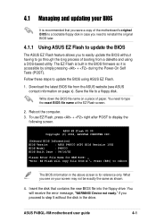
... steps to easily update the BIOS without the disk in the above screen is accessible by simply pressing + during the Power-On Self Tests (POST). What you to update the BIOS using a DOS-based utility. Reboot the computer. 3. ASUS P4BGL-VM motherboard user guide 4-1 Insert the... disk that you save a copy of the motherboard's original BIOS to a bootable floppy disk in the BIOS firmware so it is for reference only.
... steps to easily update the BIOS without the disk in the above screen is accessible by simply pressing + during the Power-On Self Tests (POST). What you to update the BIOS using a DOS-based utility. Reboot the computer. 3. ASUS P4BGL-VM motherboard user guide 4-1 Insert the... disk that you save a copy of the motherboard's original BIOS to a bootable floppy disk in the BIOS firmware so it is for reference only.
P4BGL-VM User Manual
Page 62
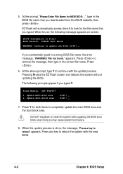
When found ." Continue to continue with the new BIOS. 4-2 Chapter 4: BIOS Setup File not found , the following prompts appear if you accidentally typed in the BIOS file name that you downloaded from the ASUS website, then press . At the above prompt, type Y to update the BIOS (Y/N)? _ If you typed Y. Update Boot Block area (Y/N)? _ (Y/N)? _ 7. Press to reboot...
When found ." Continue to continue with the new BIOS. 4-2 Chapter 4: BIOS Setup File not found , the following prompts appear if you accidentally typed in the BIOS file name that you downloaded from the ASUS website, then press . At the above prompt, type Y to update the BIOS (Y/N)? _ If you typed Y. Update Boot Block area (Y/N)? _ (Y/N)? _ 7. Press to reboot...
P4BGL-VM User Manual
Page 63
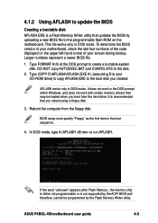
Larger numbers represent a newer BIOS file. 1. DO NOT copy AUTOEXEC.BAT and CONFIG.SYS to run AFLASH. It is recommended that may be programmed by the Flash Memory Writer utility. In DOS mode, type A:\AFLASH to the disk. 2. ASUS P4BGL-VM motherboard user guide 4-3 AFLASH works only... in the boot sequence. 4. Reboot the computer from the hard drive. Type COPY D:\AFLASH\AFLASH.EXE A:\ (assuming D is your screen during bootup. BIOS setup must specify "Floppy" as the first ...
Larger numbers represent a newer BIOS file. 1. DO NOT copy AUTOEXEC.BAT and CONFIG.SYS to run AFLASH. It is recommended that may be programmed by the Flash Memory Writer utility. In DOS mode, type A:\AFLASH to the disk. 2. ASUS P4BGL-VM motherboard user guide 4-3 AFLASH works only... in the boot sequence. 4. Reboot the computer from the hard drive. Type COPY D:\AFLASH\AFLASH.EXE A:\ (assuming D is your screen during bootup. BIOS setup must specify "Floppy" as the first ...
P4BGL-VM User Manual
Page 64
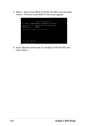
The Save Current BIOS To File screen appears. 6. Save Current BIOS to File from the Main menu and press . Select 1. 5. Type a filename and the path, for example, A:\XXX-XX.XXX, then press . 4-4 Chapter 4: BIOS Setup
The Save Current BIOS To File screen appears. 6. Save Current BIOS to File from the Main menu and press . Select 1. 5. Type a filename and the path, for example, A:\XXX-XX.XXX, then press . 4-4 Chapter 4: BIOS Setup
P4BGL-VM User Manual
Page 65
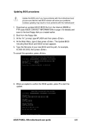
... screen appears. 5. Download an updated ASUS BIOS file from the floppy disk. 3. To cancel this operation, press . 6. Type the filename of your problems. Careless updating may result to more problems with the motherboard! 1. Updating BIOS procedures Update the BIOS only if you have problems with the... BIOS revision will solve your new BIOS and the path, for example, A:\XXX-XX.XXX, then press . Boot from the Internet (WWW or FTP) (see ASUS CONTACT INFORMATION on page x for details) and save to start the update. At the "A:\" prompt, type AFLASH and then press . 4. ASUS P4BGL-VM ...
... screen appears. 5. Download an updated ASUS BIOS file from the floppy disk. 3. To cancel this operation, press . 6. Type the filename of your problems. Careless updating may result to more problems with the motherboard! 1. Updating BIOS procedures Update the BIOS only if you have problems with the... BIOS revision will solve your new BIOS and the path, for example, A:\XXX-XX.XXX, then press . Boot from the Internet (WWW or FTP) (see ASUS CONTACT INFORMATION on page x for details) and save to start the update. At the "A:\" prompt, type AFLASH and then press . 4. ASUS P4BGL-VM ...
P4BGL-VM User Manual
Page 66
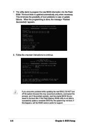
...8. This minimizes the possibility of boot problems in case of update failures. If the Flash Memory Writer utility is not able to successfully update a complete BIOS file, the system may cause boot problems. Just repeat the process, and if the problem persists, load the original... BIOS file you saved to the boot disk. Follow the onscreen instructions to program the new BIOS information into the Flash ROM. The utility starts to continue. If you encounter problems while updating the ...
...8. This minimizes the possibility of boot problems in case of update failures. If the Flash Memory Writer utility is not able to successfully update a complete BIOS file, the system may cause boot problems. Just repeat the process, and if the problem persists, load the original... BIOS file you saved to the boot disk. Follow the onscreen instructions to program the new BIOS information into the Flash ROM. The utility starts to continue. If you encounter problems while updating the ...


