
P4B-E User Manual
Page 8
...are also provided. • Chapter 5: Software support This chapter describes the contents of the support CD that you need when installing the ASUS P4B-E motherboard. About this guide This user guide contains the information you have to change system settings through the BIOS Setup menus. It ...includes brief descriptions of the special attributes of the P4B-E motherboard. viii It includes description of the topics found in this guide is organized This manual contains the following parts: • ...
...are also provided. • Chapter 5: Software support This chapter describes the contents of the support CD that you need when installing the ASUS P4B-E motherboard. About this guide This user guide contains the information you have to change system settings through the BIOS Setup menus. It ...includes brief descriptions of the special attributes of the P4B-E motherboard. viii It includes description of the topics found in this guide is organized This manual contains the following parts: • ...

P4B-E User Manual
Page 12
ASUS P4B-E motherboard
ASUS P4B-E motherboard

P4B-E User Manual
Page 13
... to set a new benchmark for an effective desktop platform solution. The ASUS P4B-E motherboard delivers a host of new features and latest technology making it , check the items in ) ASUS P4B-E support CD ASUS 2-port USB module ASUS SPDIF module (for audio models only) two 80-conductor ribbon cables for..., and hardware devices on it another standout in the long line of the above items is damaged or missing, contact your P4B-E package for the following items. ASUS P4B-E motherboard (ATX form factor: 12-in x 9.6-in your package with the list below. 1.2 Package contents Check your retailer...
... to set a new benchmark for an effective desktop platform solution. The ASUS P4B-E motherboard delivers a host of new features and latest technology making it , check the items in ) ASUS P4B-E support CD ASUS 2-port USB module ASUS SPDIF module (for audio models only) two 80-conductor ribbon cables for..., and hardware devices on it another standout in the long line of the above items is damaged or missing, contact your P4B-E package for the following items. ASUS P4B-E motherboard (ATX form factor: 12-in x 9.6-in your package with the list below. 1.2 Package contents Check your retailer...

P4B-E User Manual
Page 15
...used if you don't have at least 1A on the +5V standby lead (+5VSB). 6 Super I /O functionality. This ASUS patented auxilliary power connector is used Super I /O chipset. ASUS P4B-E motherboard user guide 1-3 1 ATX 12V connector. These three 168-pin DIMM sockets support up to prevent incorrect insertion of...of the two major components of the connector is one MPU-401 UART mode compatible MIDI/game port, and a Flash ROM interface. 7 ASUS EZ Plug™ Auxilliary +12V connector. This power connector connects the 4-pin 12V plug from a standard power supply to this connector to...
...used if you don't have at least 1A on the +5V standby lead (+5VSB). 6 Super I /O functionality. This ASUS patented auxilliary power connector is used Super I /O chipset. ASUS P4B-E motherboard user guide 1-3 1 ATX 12V connector. These three 168-pin DIMM sockets support up to prevent incorrect insertion of...of the two major components of the connector is one MPU-401 UART mode compatible MIDI/game port, and a Flash ROM interface. 7 ASUS EZ Plug™ Auxilliary +12V connector. This power connector connects the 4-pin 12V plug from a standard power supply to this connector to...
P4B-E User Manual
Page 17
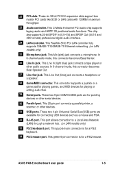
... jack. These six 32-bit PCI 2.2 expansion slots support bus master PCI cards like SCSI or LAN cards with 133MB/s maximum throughput. 23 Audio controller. ASUS P4B-E motherboard user guide 1-5 In 6-channel audio mode, this connector becomes Rear Speaker Out. 27 Line Out jack. This connector supports a joystick or a game pad for...
... jack. These six 32-bit PCI 2.2 expansion slots support bus master PCI cards like SCSI or LAN cards with 133MB/s maximum throughput. 23 Audio controller. ASUS P4B-E motherboard user guide 1-5 In 6-channel audio mode, this connector becomes Rear Speaker Out. 27 Line Out jack. This connector supports a joystick or a game pad for...

P4B-E User Manual
Page 19
...your existing power supply rather than buying a new ATX 12V power supply. The RAID chip onboard supports RAID 0 and RAID 1 configurations. ASUS P4B-E motherboard user guide 1-7 Digital audio interface On audio models, a digital audio connector is necessary to read and write data in parallel, interleaved...configuration provides data protection and increases fault tolerance to support Redundant Array of the data in the P4B-E motherboard allows you use your favorite DVDs and computer games. The ASUS EZ Plug™ is a 4-pin auxillary +12V connector mounted on the motherboard that of ...
...your existing power supply rather than buying a new ATX 12V power supply. The RAID chip onboard supports RAID 0 and RAID 1 configurations. ASUS P4B-E motherboard user guide 1-7 Digital audio interface On audio models, a digital audio connector is necessary to read and write data in parallel, interleaved...configuration provides data protection and increases fault tolerance to support Redundant Array of the data in the P4B-E motherboard allows you use your favorite DVDs and computer games. The ASUS EZ Plug™ is a 4-pin auxillary +12V connector mounted on the motherboard that of ...

P4B-E User Manual
Page 22
ASUS P4B-E motherboard
ASUS P4B-E motherboard

P4B-E User Manual
Page 23
... the chassis in the correct orientation. The edge with external ports goes to the rear part of the chassis Figure 2-1 Motherboard placement and screw holes ASUS P4B-E motherboard user guide 2-1 The P4B-E uses the ATX form factor that measures 12 inches x 9.6 inches, a standard fit for most chassis.
... the chassis in the correct orientation. The edge with external ports goes to the rear part of the chassis Figure 2-1 Motherboard placement and screw holes ASUS P4B-E motherboard user guide 2-1 The P4B-E uses the ATX form factor that measures 12 inches x 9.6 inches, a standard fit for most chassis.

P4B-E User Manual
Page 25
... LED Figure 2-3 Onboard LEDs ON Incorrect AGP Card OFF Correct AGP Card LED1 ON Standby Power OFF Powered Off ASUS P4B-E motherboard user guide 2-3 2.3 Before you proceed Take note of plugging in any 3.3V AGP card into the 1.5V AGP slot, this LED lights up thus ...
... LED Figure 2-3 Onboard LEDs ON Incorrect AGP Card OFF Correct AGP Card LED1 ON Standby Power OFF Powered Off ASUS P4B-E motherboard user guide 2-3 2.3 Before you proceed Take note of plugging in any 3.3V AGP card into the 1.5V AGP slot, this LED lights up thus ...

P4B-E User Manual
Page 27
Socket Lever 90 - 100 Figure 2-6 CPU Socket Lever at 90° -100° Angle Make sure that the socket lever is lifted up to a 90°-100° angle. ASUS P4B-E motherboard user guide 2-5 Locate the 478-pin ZIF socket on the motherboard. 2.4.2 Installing the CPU Follow these steps to 90°-100° angle, otherwise the CPU does not fit in completely. Unlock the socket by pressing the lever sideways, then lift it up to install a CPU. 1. Figure 2-5 Intel 478-pin ZIF Socket 2.
Socket Lever 90 - 100 Figure 2-6 CPU Socket Lever at 90° -100° Angle Make sure that the socket lever is lifted up to a 90°-100° angle. ASUS P4B-E motherboard user guide 2-5 Locate the 478-pin ZIF socket on the motherboard. 2.4.2 Installing the CPU Follow these steps to 90°-100° angle, otherwise the CPU does not fit in completely. Unlock the socket by pressing the lever sideways, then lift it up to install a CPU. 1. Figure 2-5 Intel 478-pin ZIF Socket 2.

P4B-E User Manual
Page 29
... a boxed Intel Pentium 4 478/Northwood Processor, the package includes the heatsink, fan, and retention mechanism. Follow these steps to ensure optimum thermal condition and performance. ASUS P4B-E motherboard user guide 2-7 Place the heatsink on the motherboard. In case you buy a CPU separately, make sure that the heatsink fits properly on the retention...
... a boxed Intel Pentium 4 478/Northwood Processor, the package includes the heatsink, fan, and retention mechanism. Follow these steps to ensure optimum thermal condition and performance. ASUS P4B-E motherboard user guide 2-7 Place the heatsink on the motherboard. In case you buy a CPU separately, make sure that the heatsink fits properly on the retention...

P4B-E User Manual
Page 31
... and fan to opposite directions. Push down the locks on the motherboard labeled CPU_FAN. When secure, the retention locks should point to the module base. ASUS P4B-E motherboard user guide 2-9
... and fan to opposite directions. Push down the locks on the motherboard labeled CPU_FAN. When secure, the retention locks should point to the module base. ASUS P4B-E motherboard user guide 2-9

P4B-E User Manual
Page 33
... until the retaining clips snap back in place and the DIMM is properly seated. Figure 2-14 Installing a DIMM Unlocked Retaining Clip Figure 2-15 Installed DIMM ASUS P4B-E motherboard user guide Locked Retaining Clip 2-11 Align a DIMM on the socket such that the notches on the DIMM match the breaks on the socket...
... until the retaining clips snap back in place and the DIMM is properly seated. Figure 2-14 Installing a DIMM Unlocked Retaining Clip Figure 2-15 Installed DIMM ASUS P4B-E motherboard user guide Locked Retaining Clip 2-11 Align a DIMM on the socket such that the notches on the DIMM match the breaks on the socket...

P4B-E User Manual
Page 35
... describe the slots and the expansion cards that came with it and make the necessary hardware settings for later use . Figure 2-17 Installing a PCI Card ASUS P4B-E motherboard user guide 2-13 Secure the card to install expansion cards. 2.6 Expansion slots In the future, you may cause you physical injury and damage motherboard...
... describe the slots and the expansion cards that came with it and make the necessary hardware settings for later use . Figure 2-17 Installing a PCI Card ASUS P4B-E motherboard user guide 2-13 Secure the card to install expansion cards. 2.6 Expansion slots In the future, you may cause you physical injury and damage motherboard...

P4B-E User Manual
Page 37
...LED is not supported on the card golden fingers to the motherboard. When you ask for 1.5v P4B-E Accelerated Graphics Port (AGP) Figure 2-19 Accelerated Graphics Port (AGP) Slot Location ASUS P4B-E motherboard user guide 2-15 Figure 2-18 Installed PCI Card 2.6.4 AGP slot This motherboard has an Accelerated...a SiS305-based AGP card or any other cards that supports +1.5V AGP cards. The following figure shows a LAN card installed on your motherboard. P4B-E ® Keyed for one with PCI specifications. If you installed an incorrect AGP card, such as a LAN card, SCSI card, USB card...
...LED is not supported on the card golden fingers to the motherboard. When you ask for 1.5v P4B-E Accelerated Graphics Port (AGP) Figure 2-19 Accelerated Graphics Port (AGP) Slot Location ASUS P4B-E motherboard user guide 2-15 Figure 2-18 Installed PCI Card 2.6.4 AGP slot This motherboard has an Accelerated...a SiS305-based AGP card or any other cards that supports +1.5V AGP cards. The following figure shows a LAN card installed on your motherboard. P4B-E ® Keyed for one with PCI specifications. If you installed an incorrect AGP card, such as a LAN card, SCSI card, USB card...

P4B-E User Manual
Page 39
...you to change CPU settings through the DIP switches. SWITCH OFF ON P4B-E ® P4B-E DIP Switches Figure 2-21 DIP Switches 1. Frequency Multiple 5. JEN OFF SWITCH P4B-E ® 12 Jumper Mode P4B-E JumperFree™ Mode Setting Figure 2-22 JumperFree Mode Setting 23 Jumper... 4. Frequency Multiple 3. The JumperFree mode allows you wish to OFF. In JumperFree mode, set all the switches in conjunction with the DIP switches. Frequency Selection 7. ASUS P4B-E motherboard user guide 2-17 ON 1 2 3 4 5 6 7 8 9 10 ON 1 2 3 4 5 6 7 8 9 10 2.7 Switches and jumpers The ...
...you to change CPU settings through the DIP switches. SWITCH OFF ON P4B-E ® P4B-E DIP Switches Figure 2-21 DIP Switches 1. Frequency Multiple 5. JEN OFF SWITCH P4B-E ® 12 Jumper Mode P4B-E JumperFree™ Mode Setting Figure 2-22 JumperFree Mode Setting 23 Jumper... 4. Frequency Multiple 3. The JumperFree mode allows you wish to OFF. In JumperFree mode, set all the switches in conjunction with the DIP switches. Frequency Selection 7. ASUS P4B-E motherboard user guide 2-17 ON 1 2 3 4 5 6 7 8 9 10 ON 1 2 3 4 5 6 7 8 9 10 2.7 Switches and jumpers The ...

P4B-E User Manual
Page 41
... 6 7 8 9 10 ON ON ON CPU PCI 100MHz 33MHz 105MHz 35MHz 111MHz 37MHz 1 2 3 4 5 6 7 8 9 10 1 2 3 4 5 6 7 8 9 10 1 2 3 4 5 6 7 8 9 10 ON ON ON P4B-E CPU PCI 120MHz 40MHz 120MHz 30MHz ® P4B-E CPU External Frequency Selection CPU PCI 133MHz 33MHz Figure 2-24 CPU Frequency Settings ON 1 2 3 4 5 6 7 8 9 10 125MHz 31MHz Set the CPU frequency only... to send the CPU. This allows the selection of the CPU's external frequency (or Bus Clock). ASUS P4B-E motherboard user guide 2-19 The BUS Clock multiplied by the Frequency Multiple equals the CPU's internal frequency (...
... 6 7 8 9 10 ON ON ON CPU PCI 100MHz 33MHz 105MHz 35MHz 111MHz 37MHz 1 2 3 4 5 6 7 8 9 10 1 2 3 4 5 6 7 8 9 10 1 2 3 4 5 6 7 8 9 10 ON ON ON P4B-E CPU PCI 120MHz 40MHz 120MHz 30MHz ® P4B-E CPU External Frequency Selection CPU PCI 133MHz 33MHz Figure 2-24 CPU Frequency Settings ON 1 2 3 4 5 6 7 8 9 10 125MHz 31MHz Set the CPU frequency only... to send the CPU. This allows the selection of the CPU's external frequency (or Bus Clock). ASUS P4B-E motherboard user guide 2-19 The BUS Clock multiplied by the Frequency Multiple equals the CPU's internal frequency (...

P4B-E User Manual
Page 43
... Out jack (lime color) on pins 2-3 (+5VSB). Set to use for the ASUS POST Reporter™ function. 5. The default is setting is the Space Bar). P4B-E ® SPEECH 12 23 SPEAKER P4B-E Speaker Selector Figure 2-27 Speaker Selection Settings LINE_OUT (Default) ASUS P4B-E motherboard user guide 2-21 Set to pins 1-2 to pins 2-3 if you press...
... Out jack (lime color) on pins 2-3 (+5VSB). Set to use for the ASUS POST Reporter™ function. 5. The default is setting is the Space Bar). P4B-E ® SPEECH 12 23 SPEAKER P4B-E Speaker Selector Figure 2-27 Speaker Selection Settings LINE_OUT (Default) ASUS P4B-E motherboard user guide 2-21 Set to pins 1-2 to pins 2-3 if you press...

P4B-E User Manual
Page 45
... pins 2-3 to use the RAID feature. RAID IDE settings (3-pin RAID_EN) (on the motherboard. P4B-E ® RAID_EN 12 23 P4B-E RAID IDE Setting Figure 2-31 RAID Settings Enable (Default) Disable ASUS P4B-E motherboard user guide 2-23 P4B-E ® RAID_SEL 12 23 P4B-E RAID Selection RAID0,1 (Default) ATA100IDE Figure 2-30 RAID Selection 10. 9. Keep the default setting...
... pins 2-3 to use the RAID feature. RAID IDE settings (3-pin RAID_EN) (on the motherboard. P4B-E ® RAID_EN 12 23 P4B-E RAID IDE Setting Figure 2-31 RAID Settings Enable (Default) Disable ASUS P4B-E motherboard user guide 2-23 P4B-E ® RAID_SEL 12 23 P4B-E RAID Selection RAID0,1 (Default) ATA100IDE Figure 2-30 RAID Selection 10. 9. Keep the default setting...

P4B-E User Manual
Page 47
... erase the RTC RAM: 1. Re-install the battery. 5. The RAM data in CMOS. Place a jumper cap over the pins for a few seconds to clear CMOS ASUS P4B-E motherboard user guide 2-25 You can clear the CMOS memory of date, time, and system setup parameters by the onboard button cell battery. Turn OFF...
... erase the RTC RAM: 1. Re-install the battery. 5. The RAM data in CMOS. Place a jumper cap over the pins for a few seconds to clear CMOS ASUS P4B-E motherboard user guide 2-25 You can clear the CMOS memory of date, time, and system setup parameters by the onboard button cell battery. Turn OFF...


