
P4B-E User Manual
Page 44
...Both jumpers are set to pins 1-2, these jumpers activate external USB ports on the internal leads of the Mic port. CNRUSB0 CNRUSB1 P4B-E ® P4B-E CNR/USB Selection 12 USE EXT CONNECTOR PORTS (Default) Figure 2-29 USB Port Selection 23 USE CNR USB 2-22 Chapter 2: Hardware information... 12 (BASS/CENTER) (Default) BCS1 BCS2 23 (CENTER/BASS) P4B-E Bass Center Setting Figure 2-28 Bass/Center Settings 8. USB port selection (3-pin CNRUSB0, CNRUSB1) When set to re-route signals on the rear panel. Use the audio driver included in the support CD to pins 2-3 activates the CNR slot....
...Both jumpers are set to pins 1-2, these jumpers activate external USB ports on the internal leads of the Mic port. CNRUSB0 CNRUSB1 P4B-E ® P4B-E CNR/USB Selection 12 USE EXT CONNECTOR PORTS (Default) Figure 2-29 USB Port Selection 23 USE CNR USB 2-22 Chapter 2: Hardware information... 12 (BASS/CENTER) (Default) BCS1 BCS2 23 (CENTER/BASS) P4B-E Bass Center Setting Figure 2-28 Bass/Center Settings 8. USB port selection (3-pin CNRUSB0, CNRUSB1) When set to re-route signals on the rear panel. Use the audio driver included in the support CD to pins 2-3 activates the CNR slot....

P4B-E User Manual
Page 59
System panel connector (20-pin PANEL) This connector accommodates several system front panel functions. The system message LED feature requires an ACPI OS and driver support. • System Management Interrupt Lead (2-pin SMISW) This 2-pin connector allows you to hear system beeps and warnings. • System Message... is received. The LED blinks when data is instantly decreased to save power and to allow the use of messages from a fax/modem. ASUS P4B-E motherboard user guide 2-37 The LED lights up when you turn on the system power, and blinks when the system is in sleep mode...
System panel connector (20-pin PANEL) This connector accommodates several system front panel functions. The system message LED feature requires an ACPI OS and driver support. • System Management Interrupt Lead (2-pin SMISW) This 2-pin connector allows you to hear system beeps and warnings. • System Message... is received. The LED blinks when data is instantly decreased to save power and to allow the use of messages from a fax/modem. ASUS P4B-E motherboard user guide 2-37 The LED lights up when you turn on the system power, and blinks when the system is in sleep mode...
P4B-E User Manual
Page 69
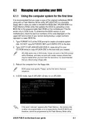
... motherboard, check the last four numbers of the code displayed on the upper left-hand corner of the original motherboard BIOS along with certain memory drivers that may be programmed by the Flash Memory Writer utility. Type FORMAT A:/S at the DOS prompt to run AFLASH. Type COPY D:\AFLASH\AFLASH.EXE A:\ (assuming... the hard drive. It is a Flash Memory Writer utility that you created. DO NOT copy AUTOEXEC.BAT and CONFIG.SYS to reinstall the BIOS later. ASUS P4B-E motherboard user guide 4-1
... motherboard, check the last four numbers of the code displayed on the upper left-hand corner of the original motherboard BIOS along with certain memory drivers that may be programmed by the Flash Memory Writer utility. Type FORMAT A:/S at the DOS prompt to run AFLASH. Type COPY D:\AFLASH\AFLASH.EXE A:\ (assuming... the hard drive. It is a Flash Memory Writer utility that you created. DO NOT copy AUTOEXEC.BAT and CONFIG.SYS to reinstall the BIOS later. ASUS P4B-E motherboard user guide 4-1

P4B-E User Manual
Page 103
... motherboard settings and hardware options vary, refer to automatically copy the RAID drivers into your CD-ROM drive. You cannot install these drivers directly from the floppy disk. Visit the ASUS website for your OS documentation for detailed installation insructions. The CD automatically ...the support CD, simply insert the CD into the floppy disk. The contents of your computer. ASUS P4B-E motherboard user guide 5-1 The RAID drivers are in the folders DRIVERS/PROMISE/ATA100. 5.2 Support CD information The support CD that came with the motherboard contains useful software...
... motherboard settings and hardware options vary, refer to automatically copy the RAID drivers into your CD-ROM drive. You cannot install these drivers directly from the floppy disk. Visit the ASUS website for your OS documentation for detailed installation insructions. The CD automatically ...the support CD, simply insert the CD into the floppy disk. The contents of your computer. ASUS P4B-E motherboard user guide 5-1 The RAID drivers are in the folders DRIVERS/PROMISE/ATA100. 5.2 Support CD information The support CD that came with the motherboard contains useful software...

P4B-E User Manual
Page 107
... Click on the Next button on the lower right corner of two screens. INF Driver This item installs the Intel® Chipset Software Installation Utility that outline to display ...the first screen to the operating system how the chipset components will be configured. The drivers menu is not required in three modes: interactive, silent, and unattended preload. To ...Accelerator This item installs the Intel Application Accelerator for Intel chipset components. Install the INF Driver before installing the Intel Application Accelerator. This utility installs to the first menu screen, ...
... Click on the Next button on the lower right corner of two screens. INF Driver This item installs the Intel® Chipset Software Installation Utility that outline to display ...the first screen to the operating system how the chipset components will be configured. The drivers menu is not required in three modes: interactive, silent, and unattended preload. To ...Accelerator This item installs the Intel Application Accelerator for Intel chipset components. Install the INF Driver before installing the Intel Application Accelerator. This utility installs to the first menu screen, ...

P4B-E User Manual
Page 127
...Self Test 4-30 POST Messages 3-2 customizing 5-16 PS/2 Keyboard Port 1-5 PS/2 Mouse Port 1-5 PS/2 Mouse Function Control 4-17 Super I/O chipset 1-4 Support CD 5-1 ASUS Update 5-3 Boot Logo 5-13 DOS Utilities 5-7 Drivers menu 5-5 Main menu 5-2 motherboard information 5-8 readme file 5-9 Software menu 5-3 Technical Support Form 5-9 Welcome screen 5-1 Winbond Voice Editor 5-14 Suspend Mode 4-25 System...CAS Delay 4-18 Z Serial Ports 1-5, 4-20 Slots ZIF socket 2-4 AGP 2-15 CNR 2-16 PCI 2-15 Smart Card Reader 2-35 SMART Monitoring 4-12 SPDIF audio 2-33 ASUS P4B-E motherboard user guide I-3
...Self Test 4-30 POST Messages 3-2 customizing 5-16 PS/2 Keyboard Port 1-5 PS/2 Mouse Port 1-5 PS/2 Mouse Function Control 4-17 Super I/O chipset 1-4 Support CD 5-1 ASUS Update 5-3 Boot Logo 5-13 DOS Utilities 5-7 Drivers menu 5-5 Main menu 5-2 motherboard information 5-8 readme file 5-9 Software menu 5-3 Technical Support Form 5-9 Welcome screen 5-1 Winbond Voice Editor 5-14 Suspend Mode 4-25 System...CAS Delay 4-18 Z Serial Ports 1-5, 4-20 Slots ZIF socket 2-4 AGP 2-15 CNR 2-16 PCI 2-15 Smart Card Reader 2-35 SMART Monitoring 4-12 SPDIF audio 2-33 ASUS P4B-E motherboard user guide I-3


