
P4B-E User Manual
Page 8
... provided. • Chapter 5: Software support This chapter describes the contents of the support CD that you need when installing the ASUS P4B-E motherboard. How this document. It includes description of the P4B-E motherboard. viii It includes brief descriptions of the special attributes of the motherboard and the new technology it supports. • Chapter...
... provided. • Chapter 5: Software support This chapter describes the contents of the support CD that you need when installing the ASUS P4B-E motherboard. How this document. It includes description of the P4B-E motherboard. viii It includes brief descriptions of the special attributes of the motherboard and the new technology it supports. • Chapter...

P4B-E User Manual
Page 12
ASUS P4B-E motherboard
ASUS P4B-E motherboard

P4B-E User Manual
Page 13
...check the items in your package with the list below. 1.2 Package contents Check your P4B-E package for the following items. ASUS P4B-E motherboard (ATX form factor: 12-in x 9.6-in) ASUS P4B-E support CD ASUS 2-port USB module ASUS SPDIF module (for audio models only) two 80-conductor ribbon cables for UltraATA/100... motherboards! Before you for an effective desktop platform solution. Supporting up to set a new benchmark for buying the ASUS® P4B-E motherboard! 1.1 Welcome! Thank you start installing the motherboard, and hardware devices on it another standout in 478-pin ...
...check the items in your package with the list below. 1.2 Package contents Check your P4B-E package for the following items. ASUS P4B-E motherboard (ATX form factor: 12-in x 9.6-in) ASUS P4B-E support CD ASUS 2-port USB module ASUS SPDIF module (for audio models only) two 80-conductor ribbon cables for UltraATA/100... motherboards! Before you for an effective desktop platform solution. Supporting up to set a new benchmark for buying the ASUS® P4B-E motherboard! 1.1 Welcome! Thank you start installing the motherboard, and hardware devices on it another standout in 478-pin ...

P4B-E User Manual
Page 15
...The MCH along with 400MHz system bus. 3 North bridge controller. Connect a 4-pin device connector from the ATX 12V power supply. 2 CPU socket. ASUS P4B-E motherboard user guide 1-3 1 ATX 12V connector. A 478-pin surface mount, Zero Insertion Force (ZIF) socket called the Intel Memory Controller Hub (...interface, and Hub Interface. 4 SDRAM DIMM sockets. The chipset supports a high-performance floppy disk controller for the floppy disk drive. This ASUS patented auxilliary power connector is slotted to four Ultra DMA/100/66, PIO Modes 3 & 4 IDE devices. These dual-channel bus ...
...The MCH along with 400MHz system bus. 3 North bridge controller. Connect a 4-pin device connector from the ATX 12V power supply. 2 CPU socket. ASUS P4B-E motherboard user guide 1-3 1 ATX 12V connector. A 478-pin surface mount, Zero Insertion Force (ZIF) socket called the Intel Memory Controller Hub (...interface, and Hub Interface. 4 SDRAM DIMM sockets. The chipset supports a high-performance floppy disk controller for the floppy disk drive. This ASUS patented auxilliary power connector is slotted to four Ultra DMA/100/66, PIO Modes 3 & 4 IDE devices. These dual-channel bus ...
P4B-E User Manual
Page 17
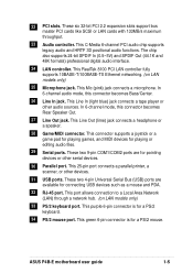
... or a speaker. 28 Game/MIDI connector. This port allows connection to a Local Area Network (LAN) through a network hub. (on LAN models only) 25 Microphone jack. ASUS P4B-E motherboard user guide 1-5 In 6-channel mode, this connector becomes Bass/Center. 26 Line In jack. 22 PCI slots. This Mic (pink) jack connects a microphone. In...
... or a speaker. 28 Game/MIDI connector. This port allows connection to a Local Area Network (LAN) through a network hub. (on LAN models only) 25 Microphone jack. ASUS P4B-E motherboard user guide 1-5 In 6-channel mode, this connector becomes Bass/Center. 26 Line In jack. 22 PCI slots. This Mic (pink) jack connects a microphone. In...

P4B-E User Manual
Page 19
... to your system using customizable boot logos. The RAID chip onboard supports RAID 0 and RAID 1 configurations. ASUS MyLogo™ This new feature present in the P4B-E motherboard allows you use your favorite DVDs and computer games. RAID 1 (called data striping) optimizes two ...RAID 1 support The motherboard includes the Promise® chip PDC20265R and two extra Ultra ATA/100/66 interfaces to a second drive. ASUS P4B-E motherboard user guide 1-7 Experience 5.1-channel surround sound and enhanced 3D audio while playing your existing power supply rather than buying a ...
... to your system using customizable boot logos. The RAID chip onboard supports RAID 0 and RAID 1 configurations. ASUS MyLogo™ This new feature present in the P4B-E motherboard allows you use your favorite DVDs and computer games. RAID 1 (called data striping) optimizes two ...RAID 1 support The motherboard includes the Promise® chip PDC20265R and two extra Ultra ATA/100/66 interfaces to a second drive. ASUS P4B-E motherboard user guide 1-7 Experience 5.1-channel surround sound and enhanced 3D audio while playing your existing power supply rather than buying a ...

P4B-E User Manual
Page 22
ASUS P4B-E motherboard
ASUS P4B-E motherboard

P4B-E User Manual
Page 23
2.1 Motherboard installation Before you install the motherboard, study the configuration of the chassis Figure 2-1 Motherboard placement and screw holes ASUS P4B-E motherboard user guide 2-1 Make sure to the rear part of the chassis. Do not overtighten the screws! Place this side ...that the motherboard fits into it into the holes indicated by circles to secure the motherboard to do so may damage the motherboard. The P4B-E uses the ATX form factor that you physical injury and damage motherboard components. 2.1.1 Placement direction When installing the motherboard, make sure ...
2.1 Motherboard installation Before you install the motherboard, study the configuration of the chassis Figure 2-1 Motherboard placement and screw holes ASUS P4B-E motherboard user guide 2-1 Make sure to the rear part of the chassis. Do not overtighten the screws! Place this side ...that the motherboard fits into it into the holes indicated by circles to secure the motherboard to do so may damage the motherboard. The P4B-E uses the ATX form factor that you physical injury and damage motherboard components. 2.1.1 Placement direction When installing the motherboard, make sure ...

P4B-E User Manual
Page 25
... LED Figure 2-3 Onboard LEDs ON Incorrect AGP Card OFF Correct AGP Card LED1 ON Standby Power OFF Powered Off ASUS P4B-E motherboard user guide 2-3 Hold components by an incorrect AGP card. If you install or remove any 3.3V AGP card into the 1.5V AGP slot, this ...
... LED Figure 2-3 Onboard LEDs ON Incorrect AGP Card OFF Correct AGP Card LED1 ON Standby Power OFF Powered Off ASUS P4B-E motherboard user guide 2-3 Hold components by an incorrect AGP card. If you install or remove any 3.3V AGP card into the 1.5V AGP slot, this ...

P4B-E User Manual
Page 27
Locate the 478-pin ZIF socket on the motherboard. ASUS P4B-E motherboard user guide 2-5 Unlock the socket by pressing the lever sideways, then lift it up to 90°-100° angle, otherwise the CPU does not fit in completely. Figure 2-5 Intel 478-pin ZIF Socket 2. Socket Lever 90 - 100 Figure 2-6 CPU Socket Lever at 90° -100° Angle Make sure that the socket lever is lifted up to install a CPU. 1. 2.4.2 Installing the CPU Follow these steps to a 90°-100° angle.
Locate the 478-pin ZIF socket on the motherboard. ASUS P4B-E motherboard user guide 2-5 Unlock the socket by pressing the lever sideways, then lift it up to 90°-100° angle, otherwise the CPU does not fit in completely. Figure 2-5 Intel 478-pin ZIF Socket 2. Socket Lever 90 - 100 Figure 2-6 CPU Socket Lever at 90° -100° Angle Make sure that the socket lever is lifted up to install a CPU. 1. 2.4.2 Installing the CPU Follow these steps to a 90°-100° angle.

P4B-E User Manual
Page 29
... mechanism. If the instructions in this section do not match the CPU documentation, follow the latter. When you use only Intel certified heatsink and fan. ASUS P4B-E motherboard user guide 2-7 Follow these steps to ensure optimum thermal condition and performance. The retention module base is already installed on the retention module base...
... mechanism. If the instructions in this section do not match the CPU documentation, follow the latter. When you use only Intel certified heatsink and fan. ASUS P4B-E motherboard user guide 2-7 Follow these steps to ensure optimum thermal condition and performance. The retention module base is already installed on the retention module base...

P4B-E User Manual
Page 31
...'t forget to opposite directions. Hardware monitoring errors may occur if you fail to the module base. 3. Push down the locks on the motherboard labeled CPU_FAN. ASUS P4B-E motherboard user guide 2-9
...'t forget to opposite directions. Hardware monitoring errors may occur if you fail to the module base. 3. Push down the locks on the motherboard labeled CPU_FAN. ASUS P4B-E motherboard user guide 2-9

P4B-E User Manual
Page 33
... the retaining clips outward. 2. Follow these steps to both the motherboard and the components. Figure 2-14 Installing a DIMM Unlocked Retaining Clip Figure 2-15 Installed DIMM ASUS P4B-E motherboard user guide Locked Retaining Clip 2-11 Align a DIMM on the socket such that the notches on the DIMM match the breaks on the socket...
... the retaining clips outward. 2. Follow these steps to both the motherboard and the components. Figure 2-14 Installing a DIMM Unlocked Retaining Clip Figure 2-15 Installed DIMM ASUS P4B-E motherboard user guide Locked Retaining Clip 2-11 Align a DIMM on the socket such that the notches on the DIMM match the breaks on the socket...

P4B-E User Manual
Page 35
... chassis with the screw you removed earlier. 6. Replace the system cover. Remove the bracket opposite the slot that they support. Figure 2-17 Installing a PCI Card ASUS P4B-E motherboard user guide 2-13 Remove the system unit cover (if your motherboard is completely seated on the slot. 5. Align the card connector with the slot...
... chassis with the screw you removed earlier. 6. Replace the system cover. Remove the bracket opposite the slot that they support. Figure 2-17 Installing a PCI Card ASUS P4B-E motherboard user guide 2-13 Remove the system unit cover (if your motherboard is completely seated on the slot. 5. Align the card connector with the slot...

P4B-E User Manual
Page 37
...card or any other cards that comply with +1.5V specification. When you ask for 1.5v P4B-E Accelerated Graphics Port (AGP) Figure 2-19 Accelerated Graphics Port (AGP) Slot Location ASUS P4B-E motherboard user guide 2-15 If you press the power button, thus preventing permanent damage to... ensure that the card is lighted, you cannot turn on the motherboard. P4B-E ® Keyed for one with PCI specifications. The...
...card or any other cards that comply with +1.5V specification. When you ask for 1.5v P4B-E Accelerated Graphics Port (AGP) Figure 2-19 Accelerated Graphics Port (AGP) Slot Location ASUS P4B-E motherboard user guide 2-15 If you press the power button, thus preventing permanent damage to... ensure that the card is lighted, you cannot turn on the motherboard. P4B-E ® Keyed for one with PCI specifications. The...

P4B-E User Manual
Page 39
...Frequency Selection 6. Frequency Multiple 5. JumperFree™ mode (JEN) This jumper allows you to OFF. JEN OFF SWITCH P4B-E ® 12 Jumper Mode P4B-E JumperFree™ Mode Setting Figure 2-22 JumperFree Mode Setting 23 Jumper Free (Default) The JEN jumper is adjusted through...instead of using the DIP switches. The illustration below shows all the DIP switches to enable or disable the JumperFree™ mode. ASUS P4B-E motherboard user guide 2-17 Frequency Multiple 4. Frequency Selection 8. Otherwise, setting the switches does not produce any effect. 1. The...
...Frequency Selection 6. Frequency Multiple 5. JumperFree™ mode (JEN) This jumper allows you to OFF. JEN OFF SWITCH P4B-E ® 12 Jumper Mode P4B-E JumperFree™ Mode Setting Figure 2-22 JumperFree Mode Setting 23 Jumper Free (Default) The JEN jumper is adjusted through...instead of using the DIP switches. The illustration below shows all the DIP switches to enable or disable the JumperFree™ mode. ASUS P4B-E motherboard user guide 2-17 Frequency Multiple 4. Frequency Selection 8. Otherwise, setting the switches does not produce any effect. 1. The...

P4B-E User Manual
Page 41
...10 1 2 3 4 5 6 7 8 9 10 ON ON ON CPU PCI 100MHz 33MHz 105MHz 35MHz 111MHz 37MHz 1 2 3 4 5 6 7 8 9 10 1 2 3 4 5 6 7 8 9 10 1 2 3 4 5 6 7 8 9 10 ON ON ON P4B-E CPU PCI 120MHz 40MHz 120MHz 30MHz ® P4B-E CPU External Frequency Selection CPU PCI 133MHz 33MHz Figure 2-24 CPU Frequency Settings ON 1 2 3 4 5 6 7 8 9 10 125MHz 31MHz Set the CPU frequency only to...to send the CPU. This allows the selection of the CPU's external frequency (or Bus Clock). ASUS P4B-E motherboard user guide 2-19 The BUS Clock multiplied by the Frequency Multiple equals the CPU's internal ...
...10 1 2 3 4 5 6 7 8 9 10 ON ON ON CPU PCI 100MHz 33MHz 105MHz 35MHz 111MHz 37MHz 1 2 3 4 5 6 7 8 9 10 1 2 3 4 5 6 7 8 9 10 1 2 3 4 5 6 7 8 9 10 ON ON ON P4B-E CPU PCI 120MHz 40MHz 120MHz 30MHz ® P4B-E CPU External Frequency Selection CPU PCI 133MHz 33MHz Figure 2-24 CPU Frequency Settings ON 1 2 3 4 5 6 7 8 9 10 125MHz 31MHz Set the CPU frequency only to...to send the CPU. This allows the selection of the CPU's external frequency (or Bus Clock). ASUS P4B-E motherboard user guide 2-19 The BUS Clock multiplied by the Frequency Multiple equals the CPU's internal ...

P4B-E User Manual
Page 43
...Out jack (lime color) on the +5VSB lead, and a corresponding setting in the chassis). P4B-E ® SPEECH 12 23 SPEAKER P4B-E Speaker Selector Figure 2-27 Speaker Selection Settings LINE_OUT (Default) ASUS P4B-E motherboard user guide 2-21 5. Set to pins 1-2 to wake up feature. Speaker selector (3-...pin SPEECH) (on audio models only) This jumper allows you to select the speaker you wish to use for the ASUS POST Reporter™ function...
...Out jack (lime color) on the +5VSB lead, and a corresponding setting in the chassis). P4B-E ® SPEECH 12 23 SPEAKER P4B-E Speaker Selector Figure 2-27 Speaker Selection Settings LINE_OUT (Default) ASUS P4B-E motherboard user guide 2-21 5. Set to pins 1-2 to wake up feature. Speaker selector (3-...pin SPEECH) (on audio models only) This jumper allows you to select the speaker you wish to use for the ASUS POST Reporter™ function...

P4B-E User Manual
Page 45
... 12 23 P4B-E RAID Selection RAID0,1 (Default) ATA100IDE Figure 2-30 RAID Selection 10. RAID IDE settings (3-pin RAID_EN) (on the motherboard. Keep the default setting (pins 1-2) to use ... 2-3 to use RAID configuration. If you select the RAID feature, make sure that the RAID_EN jumper is disabled. P4B-E ® RAID_EN 12 23 P4B-E RAID IDE Setting Figure 2-31 RAID Settings Enable (Default) Disable ASUS P4B-E motherboard user guide 2-23 RAID selection (3-pin RAID_SEL) (on RAID models only) This jumper selects either RAID 0/RAID...
... 12 23 P4B-E RAID Selection RAID0,1 (Default) ATA100IDE Figure 2-30 RAID Selection 10. RAID IDE settings (3-pin RAID_EN) (on the motherboard. Keep the default setting (pins 1-2) to use ... 2-3 to use RAID configuration. If you select the RAID feature, make sure that the RAID_EN jumper is disabled. P4B-E ® RAID_EN 12 23 P4B-E RAID IDE Setting Figure 2-31 RAID Settings Enable (Default) Disable ASUS P4B-E motherboard user guide 2-23 RAID selection (3-pin RAID_SEL) (on RAID models only) This jumper selects either RAID 0/RAID...

P4B-E User Manual
Page 47
... RTC RAM CLR_CMOS Short jumper to short the jumper. Remove the jumper cap. 4. Place a jumper cap over the pins for a few seconds to clear CMOS ASUS P4B-E motherboard user guide 2-25 To erase the RTC RAM: 1. The RAM data in CMOS. You can clear the CMOS memory of date, time, and system...
... RTC RAM CLR_CMOS Short jumper to short the jumper. Remove the jumper cap. 4. Place a jumper cap over the pins for a few seconds to clear CMOS ASUS P4B-E motherboard user guide 2-25 To erase the RTC RAM: 1. The RAM data in CMOS. You can clear the CMOS memory of date, time, and system...


