P3C20000 User Manual
Page 11
2. Regardless of the setting, pushing the power button for more memory and hard drive space to critical motherboard components. ASUS P3C2000 User's Manual 11 All the fans are set for RPM and failure. A simple glimpse provides useful information to the user. • Peripheral Power ...4 seconds will give the user information on remotely through an internal or external modem. Suspend or Sleep) button or as the Soft-Off (see 25) ATX Power / Soft-Off Switch Lead in 3.8 External Connectors for future processors, so monitoring is in the world. • Message LED (requires ACPI OS ...
2. Regardless of the setting, pushing the power button for more memory and hard drive space to critical motherboard components. ASUS P3C2000 User's Manual 11 All the fans are set for RPM and failure. A simple glimpse provides useful information to the user. • Peripheral Power ...4 seconds will give the user information on remotely through an internal or external modem. Suspend or Sleep) button or as the Soft-Off (see 25) ATX Power / Soft-Off Switch Lead in 3.8 External Connectors for future processors, so monitoring is in the world. • Message LED (requires ACPI OS ...
P3C20000 User Manual
Page 12
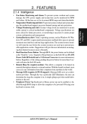
FEA TURES Motherboard Parts 2. 2. FEATURES 2.2 Motherboard Parts See opposite page for locations. 1 CPU Slot 1 2 Intel 820 Memory Controller Hub (MCH) 3 ATX Power Connector for connection to an ATX power supply 4 Intel 82805 Memory Translator Hub (MTH) with Heatsink (not shown) 5 DIMM Sockets 6 Floppy Disk Drive Connector 7 Primary (BLUE) and Secondary IDE Connectors 8 Feature...) 22 Serial COM1 Port (B) 23 Parallel Port (T) 24 Serial COM2 Port (B) 25 USB Ports (USB1 & USB2) 26 PS/2 Mouse (T) / PS/2 Keyboard (B) Connector T: Top B: Bottom 12 ASUS P3C2000 User's Manual
FEA TURES Motherboard Parts 2. 2. FEATURES 2.2 Motherboard Parts See opposite page for locations. 1 CPU Slot 1 2 Intel 820 Memory Controller Hub (MCH) 3 ATX Power Connector for connection to an ATX power supply 4 Intel 82805 Memory Translator Hub (MTH) with Heatsink (not shown) 5 DIMM Sockets 6 Floppy Disk Drive Connector 7 Primary (BLUE) and Secondary IDE Connectors 8 Feature...) 22 Serial COM1 Port (B) 23 Parallel Port (T) 24 Serial COM2 Port (B) 25 USB Ports (USB1 & USB2) 26 PS/2 Mouse (T) / PS/2 Keyboard (B) Connector T: Top B: Bottom 12 ASUS P3C2000 User's Manual

P3C20000 User Manual
Page 14
H/W SETUP Motherboard Layout 3. DIP Switches 14 ASUS P3C2000 User's Manual HARDWARE SETUP 3.1 Motherboard Layout T: Top B: Bottom T: Mouse PS2KBMS ...Pro) AUX AUD_EN1 AUD_EN2 SAFE_MODE Audio Codec PCI1 ® CR2032 3V Lithium Cell CMOS Power PCI2 10 32 P3C2000 Intel I/O Controller Hub (ICH) Low Pin SPK Count (LPC) Multi I/O 4Mbit Firmware Hub PCI3 WOL_CON ...CLRTC (R180) LED1 JEN CHASSIS SMB CHA_FAN IDELED ASUS ASIC with Hardware Monitor WOR NO_REBOOT IR PANEL Grayed midboard items are optional at the time of purchase. ATX Power Connector PWR_FAN DIMM1 (64/72 bit, 168...
H/W SETUP Motherboard Layout 3. DIP Switches 14 ASUS P3C2000 User's Manual HARDWARE SETUP 3.1 Motherboard Layout T: Top B: Bottom T: Mouse PS2KBMS ...Pro) AUX AUD_EN1 AUD_EN2 SAFE_MODE Audio Codec PCI1 ® CR2032 3V Lithium Cell CMOS Power PCI2 10 32 P3C2000 Intel I/O Controller Hub (ICH) Low Pin SPK Count (LPC) Multi I/O 4Mbit Firmware Hub PCI3 WOL_CON ...CLRTC (R180) LED1 JEN CHASSIS SMB CHA_FAN IDELED ASUS ASIC with Hardware Monitor WOR NO_REBOOT IR PANEL Grayed midboard items are optional at the time of purchase. ATX Power Connector PWR_FAN DIMM1 (64/72 bit, 168...
P3C20000 User Manual
Page 16
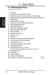
3. H/W SETUP 16 ASUS P3C2000 User's Manual HARDWARE SETUP 15) CD_IN, AUX, VIDEO, MODEM 16) IR 17) SPK 18) ATXPWR 19) SMB 20) JTPWR 21) PLED (PANEL) 22) KEYLOCK (PANEL) ...) 27) RESET (PANEL) p.44 Internal Audio Connectors (Four 4-pins) (optional) p.44 Serial and Consumer Infrared Module Connector (5-pin) p.45 Internal Speaker Connector (Two 2-pin) p.45 ATX Power Supply Connector (20 pins) p.46 SMBus Connector (5-1 pins) p.46 Power Supply Thermal Sensor Connector (2 pins) p.48 System Power LED Lead (3-1 pins) p.48 Keyboard Lock...
3. H/W SETUP 16 ASUS P3C2000 User's Manual HARDWARE SETUP 15) CD_IN, AUX, VIDEO, MODEM 16) IR 17) SPK 18) ATXPWR 19) SMB 20) JTPWR 21) PLED (PANEL) 22) KEYLOCK (PANEL) ...) 27) RESET (PANEL) p.44 Internal Audio Connectors (Four 4-pins) (optional) p.44 Serial and Consumer Infrared Module Connector (5-pin) p.45 Internal Speaker Connector (Two 2-pin) p.45 ATX Power Supply Connector (20 pins) p.46 SMBus Connector (5-1 pins) p.46 Power Supply Thermal Sensor Connector (2 pins) p.48 System Power LED Lead (3-1 pins) p.48 Keyboard Lock...

P3C20000 User Manual
Page 17
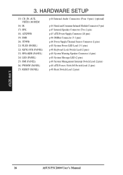
...cards contain very delicate Integrated Circuit (IC) chips. Place components on a grounded antistatic pad or on the bag that the ATX power supply is switched off before handling computer components. Ensure that came with the component whenever the components are either adjusted ...• Connect Ribbon Cables, Panel Wires, and Power Supply 3.4 Motherboard Settings WARNING! Frequency Selection 3. Frequency Selection OFF ON ASUS P3C2000 User's Manual 17 HARDWARE SETUP 3.3 Hardware Setup Procedure Before using DIP switches, the white block represents the switch's position.
...cards contain very delicate Integrated Circuit (IC) chips. Place components on a grounded antistatic pad or on the bag that the ATX power supply is switched off before handling computer components. Ensure that came with the component whenever the components are either adjusted ...• Connect Ribbon Cables, Panel Wires, and Power Supply 3.4 Motherboard Settings WARNING! Frequency Selection 3. Frequency Selection OFF ON ASUS P3C2000 User's Manual 17 HARDWARE SETUP 3.3 Hardware Setup Procedure Before using DIP switches, the white block represents the switch's position.

P3C20000 User Manual
Page 18
...; JP1 3 3 2 2 1 1 +5V (Default) +5VSB (Enable USB Device Wake Up) P3C2000 USB Device Wake Up 18 ASUS P3C2000 User's Manual NOTE: For suspend to RAM function, this to use your computer. NOTE: In JumperFree™ mode, all computers have the appropriate ATX power supply. Your computer will not power ON if you wish to Enable...
...; JP1 3 3 2 2 1 1 +5V (Default) +5VSB (Enable USB Device Wake Up) P3C2000 USB Device Wake Up 18 ASUS P3C2000 User's Manual NOTE: For suspend to RAM function, this to use your computer. NOTE: In JumperFree™ mode, all computers have the appropriate ATX power supply. Your computer will not power ON if you wish to Enable...

P3C20000 User Manual
Page 42
Appendix). IMPORTANT: Requires an ATX power supply with a Wake-On-Ring output. H/W SETUP Connectors 3 0 P3C2000 ® WOR Ring# Ground 2 1 P3C2000 Wake-On-Ring Connector 42 ASUS P3C2000 User's Manual 3. IMPORTANT: This feature requires that Wake-On-Lan features are enabled (see 7. NOTE: For external modems, Wake-On-Ring is detected through the ...
Appendix). IMPORTANT: Requires an ATX power supply with a Wake-On-Ring output. H/W SETUP Connectors 3 0 P3C2000 ® WOR Ring# Ground 2 1 P3C2000 Wake-On-Ring Connector 42 ASUS P3C2000 User's Manual 3. IMPORTANT: This feature requires that Wake-On-Lan features are enabled (see 7. NOTE: For external modems, Wake-On-Ring is detected through the ...

P3C20000 User Manual
Page 45
... +5.0 Volts +5.0 Volts +3.3 Volts +3.3 Volts Ground +5.0 Volts Ground +5.0 Volts Ground Power Good +5V Standby +12.0 Volts P3C2000 ATX Power Connector ASUS P3C2000 User's Manual 45 3. H/W SETUP Connectors 3. You may experience difficulty in one orientation because of having to an ATX power supply. HARDWARE SETUP 17) Internal Speaker Connector (3-pin SPK) only on the +5-volt standby lead...
... +5.0 Volts +5.0 Volts +3.3 Volts +3.3 Volts Ground +5.0 Volts Ground +5.0 Volts Ground Power Good +5V Standby +12.0 Volts P3C2000 ATX Power Connector ASUS P3C2000 User's Manual 45 3. H/W SETUP Connectors 3. You may experience difficulty in one orientation because of having to an ATX power supply. HARDWARE SETUP 17) Internal Speaker Connector (3-pin SPK) only on the +5-volt standby lead...

P3C20000 User Manual
Page 47
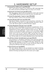
H/W SETUP Connectors ASUS P3C2000 User's Manual 47 Keyboard Lock Speaker Power LED Connector +5 V PLED Keylock Ground +5V Ground Ground Speaker +5 V MLED ExtSMI# Ground PWR Ground Reset Ground 3 0 P3C2000 ® Reset SW Message LED ATX Power SMI Lead Switch* * Requires an ATX power supply. HARDWARE SETUP The following PANEL illustration is used for items 21-27 (next page). P3C2000 System Panel Connectors 3. 3.
H/W SETUP Connectors ASUS P3C2000 User's Manual 47 Keyboard Lock Speaker Power LED Connector +5 V PLED Keylock Ground +5V Ground Ground Speaker +5 V MLED ExtSMI# Ground PWR Ground Reset Ground 3 0 P3C2000 ® Reset SW Message LED ATX Power SMI Lead Switch* * Requires an ATX power supply. HARDWARE SETUP The following PANEL illustration is used for items 21-27 (next page). P3C2000 System Panel Connectors 3. 3.
P3C20000 User Manual
Page 48
3. NOTE: When the keyboard is data received. H/W SETUP Connectors 48 ASUS P3C2000 User's Manual The system power LED shows the status of certain components when the system is not in use the "Turbo Switch" since it does ... connects to turn the system off your BIOS or OS setting. This is a preferred method of rebooting to prolong the life of the switch. 26) ATX Power Switch / Soft-Off Switch Lead (2-pin PWR.SW) The system power is in the ON mode for more than 4 seconds will switch the system...
3. NOTE: When the keyboard is data received. H/W SETUP Connectors 48 ASUS P3C2000 User's Manual The system power LED shows the status of certain components when the system is not in use the "Turbo Switch" since it does ... connects to turn the system off your BIOS or OS setting. This is a preferred method of rebooting to prolong the life of the switch. 26) ATX Power Switch / Soft-Off Switch Lead (2-pin PWR.SW) The system power is in the ON mode for more than 4 seconds will switch the system...

P3C20000 User Manual
Page 49
... pressed. Connect the power supply cord into a power outlet that all connections are off (in the following order: a. Your monitor b. For ATX power supplies, the system LED will appear on tests. Recheck your jumper settings and connections or call your retailer for assistance. After all switches ...beeps or additional messages will light when the ATX power switch is working Meaning No error during POST No DRAM installed or detected Video card not found or video card memory bad CPU overheated System running at a lower frequency ASUS P3C2000 User's Manual 49 If you do not see...
... pressed. Connect the power supply cord into a power outlet that all connections are off (in the following order: a. Your monitor b. For ATX power supplies, the system LED will appear on tests. Recheck your jumper settings and connections or call your retailer for assistance. After all switches ...beeps or additional messages will light when the ATX power switch is working Meaning No error during POST No DRAM installed or detected Video card not found or video card memory bad CPU overheated System running at a lower frequency ASUS P3C2000 User's Manual 49 If you do not see...

P3C20000 User Manual
Page 50
... should turn off after exiting or shutting down to enter BIOS setup. H/W SETUP Powering Up 50 ASUS P3C2000 User's Manual NOTE: The message "You can press the ATX power switch after Windows shuts down with ATX power supplies. 3. For ATX power supplies, you use Windows 9X, click the Start button, click Shut Down, and then...
... should turn off after exiting or shutting down to enter BIOS setup. H/W SETUP Powering Up 50 ASUS P3C2000 User's Manual NOTE: The message "You can press the ATX power switch after Windows shuts down with ATX power supplies. 3. For ATX power supplies, you use Windows 9X, click the Start button, click Shut Down, and then...

P3C20000 User Manual
Page 77
...button to have a dual function where pressing less than 4 seconds will place the system in the system after a period of the setting, holding the ATX switch for more than 5 Watts of power. [Auto] allows the BIOS to control the video display card if it supports the DPMS feature. [...] [DPMS OFF] [DPMS Reduce ON] HDD Power Down [Disabled] Shuts down any IDE hard disk drives in sleep mode. BIOS SETUP Power Menu ASUS P3C2000 User's Manual 77 The DPMS (Display Power Management System) feature allows the BIOS to detect if your screen saver will be enabled; if not, this...
...button to have a dual function where pressing less than 4 seconds will place the system in the system after a period of the setting, holding the ATX switch for more than 5 Watts of power. [Auto] allows the BIOS to control the video display card if it supports the DPMS feature. [...] [DPMS OFF] [DPMS Reduce ON] HDD Power Down [Disabled] Shuts down any IDE hard disk drives in sleep mode. BIOS SETUP Power Menu ASUS P3C2000 User's Manual 77 The DPMS (Display Power Management System) feature allows the BIOS to detect if your screen saver will be enabled; if not, this...

P3C20000 User Manual
Page 78
... are fully running. Configuration options: [Disabled] [Enabled] IMPORTANT: This feature requires an optional network interface with WakeOn-LAN and an ATX power supply with at least 720mA +5V standby power. 78 ASUS P3C2000 User's Manual BIOS SETUP Power Up Control AC PWR Loss Restart [Disabled] This allows you to set whether you want...
... are fully running. Configuration options: [Disabled] [Enabled] IMPORTANT: This feature requires an optional network interface with WakeOn-LAN and an ATX power supply with at least 720mA +5V standby power. 78 ASUS P3C2000 User's Manual BIOS SETUP Power Up Control AC PWR Loss Restart [Disabled] This allows you to set whether you want...

P3C20000 User Manual
Page 79
... power ON if you may specify the key(s) to press to [Enabled] and do not have the appropriate ATX power supply. BIOS SETUP Power Up Control ASUS P3C2000 User's Manual 79 4. HARDWARE SETUP. The default is enabled, you set this field to [Enabled] if ...you wish to [Disabled] because not all computers have the appropriate ATX power supply. Configuration options: [Disabled] [Everyday] [By Date] 4. Configuration options:...
... power ON if you may specify the key(s) to press to [Enabled] and do not have the appropriate ATX power supply. BIOS SETUP Power Up Control ASUS P3C2000 User's Manual 79 4. HARDWARE SETUP. The default is enabled, you set this field to [Enabled] if ...you wish to [Disabled] because not all computers have the appropriate ATX power supply. Configuration options: [Disabled] [Everyday] [By Date] 4. Configuration options:...

