
P3C20000 User Manual
Page 4
...First Use of the Computer System 51 4.1.2 Updating BIOS Procedures 52 4 ASUS P3C2000 User's Manual HARDWARE SETUP 14 3.1 Motherboard Layout 14 3.2 Layout Contents 15 3.3 Hardware Setup Procedure 17 3.4 Motherboard Settings 17 3.5 System Memory (DIMM 24 3.5.1 General DIMM Notes 24 3.5.2 DIMM Installation 26 3.6... Connectors 38 3.8 External Connectors 38 3.9 Starting Up the First Time 49 4. CONTENTS 1. FEATURES 8 2.1 The ASUS P3C2000 8 2.1.1 Specifications 8 2.1.2 Specifications-Optional Components 9 2.1.3 Performance 10 2.1.4 Intelligence 11 2.2 Motherboard Parts 12 3.
...First Use of the Computer System 51 4.1.2 Updating BIOS Procedures 52 4 ASUS P3C2000 User's Manual HARDWARE SETUP 14 3.1 Motherboard Layout 14 3.2 Layout Contents 15 3.3 Hardware Setup Procedure 17 3.4 Motherboard Settings 17 3.5 System Memory (DIMM 24 3.5.1 General DIMM Notes 24 3.5.2 DIMM Installation 26 3.6... Connectors 38 3.8 External Connectors 38 3.9 Starting Up the First Time 49 4. CONTENTS 1. FEATURES 8 2.1 The ASUS P3C2000 8 2.1.1 Specifications 8 2.1.2 Specifications-Optional Components 9 2.1.3 Performance 10 2.1.4 Intelligence 11 2.2 Motherboard Parts 12 3.

P3C20000 User Manual
Page 8
...174; II 100MHz FSB SECC Intel Celeron™ 100MHz FSB SEPP • Intel 820 Chipset: Features the Intel® 820 chipset (Memory Controller Hub and I/O Controller Hub) with support for high performance, component level interconnect targeted at 3D graphical applications using a 1X, 2X,... manual adjustment of up to 66.6MBps; sis panel open events into LDCM. raphy, digital signing, and other latest power computing features. 8 ASUS P3C2000 User's Manual Supports UltraDMA/66, UltraDMA/33, PIO Modes 3 & 4 and Bus Master IDE DMA Mode 2, and Enhanced IDE devices, such...
...174; II 100MHz FSB SECC Intel Celeron™ 100MHz FSB SEPP • Intel 820 Chipset: Features the Intel® 820 chipset (Memory Controller Hub and I/O Controller Hub) with support for high performance, component level interconnect targeted at 3D graphical applications using a 1X, 2X,... manual adjustment of up to 66.6MBps; sis panel open events into LDCM. raphy, digital signing, and other latest power computing features. 8 ASUS P3C2000 User's Manual Supports UltraDMA/66, UltraDMA/33, PIO Modes 3 & 4 and Bus Master IDE DMA Mode 2, and Enhanced IDE devices, such...
P3C20000 User Manual
Page 9
ter busses to the memory and processor. 2.1.2 Specifications-Optional Components The following onboard components are...speed UART compatible serial ports and one 16-bit ISA expansion slots and four PCI with EPP and ECP capabilities. ASUS P3C2000 User's Manual 9 FEA TURES Optional Components 2. FEATURES • SMBus: Features the System Management Bus interface, which... information, such as CPU and systerm voltages, temperatures, and fan status through the onboard hardware ASUS ASIC and the bundled ASUS PC Probe or Intel LDCM software. • AMR Slot: Audio Modem Riser slot supports a...
ter busses to the memory and processor. 2.1.2 Specifications-Optional Components The following onboard components are...speed UART compatible serial ports and one 16-bit ISA expansion slots and four PCI with EPP and ECP capabilities. ASUS P3C2000 User's Manual 9 FEA TURES Optional Components 2. FEATURES • SMBus: Features the System Management Bus interface, which... information, such as CPU and systerm voltages, temperatures, and fan status through the onboard hardware ASUS ASIC and the bundled ASUS PC Probe or Intel LDCM software. • AMR Slot: Audio Modem Riser slot supports a...

P3C20000 User Manual
Page 10
...-level goals: support for Plug and Play compatibility and power management for configuring and managing all ASUS smart series motherboards. The new PC 99 requirements for systems and components are based on all ... transfer rate to -RAM (STR) provides maximum power savings as required by PC 99. 10 ASUS P3C2000 User's Manual ACPI provides more Energy Saving Features for Windows 95/98/NT. To fully utilize ... allows multiple PCI transfers from PCI master buses to memory to CPU. • SDRAM Optimized Performance: This motherboard supports PC100-compliant Synchronous Dynamic Random Access...
...-level goals: support for Plug and Play compatibility and power management for configuring and managing all ASUS smart series motherboards. The new PC 99 requirements for systems and components are based on all ... transfer rate to -RAM (STR) provides maximum power savings as required by PC 99. 10 ASUS P3C2000 User's Manual ACPI provides more Energy Saving Features for Windows 95/98/NT. To fully utilize ... allows multiple PCI transfers from PCI master buses to memory to CPU. • SDRAM Optimized Performance: This motherboard supports PC100-compliant Synchronous Dynamic Random Access...
P3C20000 User Manual
Page 11
...internal or external modem. All the fans are monitored to ensure stable current to be powered ON using your keyboard or mouse click. ASUS P3C2000 User's Manual 11 With this motherboard supports processor thermal sensing and auto-protection. • Voltage Monitoring and Alert: System voltage levels ...from their limited resources more information) button. Suspend or Sleep) button or as Windows 98, Windows NT, and OS/2, require much more memory and hard drive space to be monitored for future processors, so monitoring is in the world. • Message LED (requires ACPI OS ...
...internal or external modem. All the fans are monitored to ensure stable current to be powered ON using your keyboard or mouse click. ASUS P3C2000 User's Manual 11 With this motherboard supports processor thermal sensing and auto-protection. • Voltage Monitoring and Alert: System voltage levels ...from their limited resources more information) button. Suspend or Sleep) button or as Windows 98, Windows NT, and OS/2, require much more memory and hard drive space to be monitored for future processors, so monitoring is in the world. • Message LED (requires ACPI OS ...
P3C20000 User Manual
Page 12
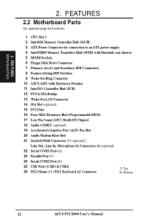
2. FEATURES 2.2 Motherboard Parts See opposite page for locations. 1 CPU Slot 1 2 Intel 820 Memory Controller Hub (MCH) 3 ATX Power Connector for connection to an ATX power supply 4 Intel 82805 Memory Translator Hub (MTH) with Heatsink (not shown) 5 DIMM Sockets 6 Floppy Disk Drive Connector 7 Primary (BLUE) and Secondary IDE Connectors 8 Feature Setting DIP ...Serial COM1 Port (B) 23 Parallel Port (T) 24 Serial COM2 Port (B) 25 USB Ports (USB1 & USB2) 26 PS/2 Mouse (T) / PS/2 Keyboard (B) Connector T: Top B: Bottom 12 ASUS P3C2000 User's Manual FEA TURES Motherboard Parts 2.
2. FEATURES 2.2 Motherboard Parts See opposite page for locations. 1 CPU Slot 1 2 Intel 820 Memory Controller Hub (MCH) 3 ATX Power Connector for connection to an ATX power supply 4 Intel 82805 Memory Translator Hub (MTH) with Heatsink (not shown) 5 DIMM Sockets 6 Floppy Disk Drive Connector 7 Primary (BLUE) and Secondary IDE Connectors 8 Feature Setting DIP ...Serial COM1 Port (B) 23 Parallel Port (T) 24 Serial COM2 Port (B) 25 USB Ports (USB1 & USB2) 26 PS/2 Mouse (T) / PS/2 Keyboard (B) Connector T: Top B: Bottom 12 ASUS P3C2000 User's Manual FEA TURES Motherboard Parts 2.

P3C20000 User Manual
Page 14
...Top B: Bottom T: Mouse PS2KBMS B: Keyboard JP2702 USB CPU_FAN1 T: USB1 JP5 B: USB2 JP1 COM2 JP3 Slot1 CPU PARALLEL PORT COM1 JTPWR Intel 820 Memory Controller Hub (MCH) Intel 82805 Memory Translator Hub (MTH) GAME_AUDIO OPTIONAL Line Out Line In Mic In Audio Modem Riser (AMR) Row 0 1 2 3 VIDEO ADN# CD_IN MODEM... with Hardware Monitor WOR NO_REBOOT IR PANEL Grayed midboard items are optional at the time of purchase. DIP Switches 14 ASUS P3C2000 User's Manual ATX Power Connector PWR_FAN DIMM1 (64/72 bit, 168-pin module) DIMM2 (64/72 bit, 168-pin module) DIMM3 (...
...Top B: Bottom T: Mouse PS2KBMS B: Keyboard JP2702 USB CPU_FAN1 T: USB1 JP5 B: USB2 JP1 COM2 JP3 Slot1 CPU PARALLEL PORT COM1 JTPWR Intel 820 Memory Controller Hub (MCH) Intel 82805 Memory Translator Hub (MTH) GAME_AUDIO OPTIONAL Line Out Line In Mic In Audio Modem Riser (AMR) Row 0 1 2 3 VIDEO ADN# CD_IN MODEM... with Hardware Monitor WOR NO_REBOOT IR PANEL Grayed midboard items are optional at the time of purchase. DIP Switches 14 ASUS P3C2000 User's Manual ATX Power Connector PWR_FAN DIMM1 (64/72 bit, 168-pin module) DIMM2 (64/72 bit, 168-pin module) DIMM3 (...
P3C20000 User Manual
Page 15
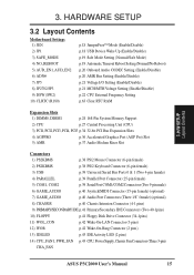
.../Disable) p.21 MCH/MTH Voltage Setting (Enable/Disable) p.22 CPU External Frequency Setting p.63 Clear RTC RAM Expansion Slots 1) DIMM0, DIMM1 p.24 168-Pin System Memory Support 2) CPU p.27 Central Processing Unit (CPU) 3) PCI1, PCI2, PCI3, PCI4, PCI5 p.34 32-bit PCI Bus Expansion Slots 4) AGPPRO p.36 Accelerated Graphics Port (AGP... Wake-On-Ring Connector (2 pins) 13) IDELED p.43 IDE Activity LED (2 pins) 14) CPU_FAN1, PWR_FAN p.43 CPU, Power Supply, Chassis Fan Connectors (Three 3-pin) CHA_FAN ASUS P3C2000 User's Manual 15
.../Disable) p.21 MCH/MTH Voltage Setting (Enable/Disable) p.22 CPU External Frequency Setting p.63 Clear RTC RAM Expansion Slots 1) DIMM0, DIMM1 p.24 168-Pin System Memory Support 2) CPU p.27 Central Processing Unit (CPU) 3) PCI1, PCI2, PCI3, PCI4, PCI5 p.34 32-bit PCI Bus Expansion Slots 4) AGPPRO p.36 Accelerated Graphics Port (AGP... Wake-On-Ring Connector (2 pins) 13) IDELED p.43 IDE Activity LED (2 pins) 14) CPU_FAN1, PWR_FAN p.43 CPU, Power Supply, Chassis Fan Connectors (Three 3-pin) CHA_FAN ASUS P3C2000 User's Manual 15

P3C20000 User Manual
Page 17
... your hands to a safely grounded object or to touch the IC chips, leads or connectors, or other components. 4. Frequency Selection OFF ON ASUS P3C2000 User's Manual 17 3. Hold components by the edges and try not to a metal object, such as the power supply case. 3. If ...you do not have one, touch both of your computer, you must complete the following steps: • Check Motherboard Settings • Install Memory Modules • Install the Central Processing Unit (CPU) • Install Expansion Cards • Connect Ribbon Cables, Panel Wires, and Power Supply 3.4 ...
... your hands to a safely grounded object or to touch the IC chips, leads or connectors, or other components. 4. Frequency Selection OFF ON ASUS P3C2000 User's Manual 17 3. Hold components by the edges and try not to a metal object, such as the power supply case. 3. If ...you do not have one, touch both of your computer, you must complete the following steps: • Check Motherboard Settings • Install Memory Modules • Install the Central Processing Unit (CPU) • Install Expansion Cards • Connect Ribbon Cables, Panel Wires, and Power Supply 3.4 ...
P3C20000 User Manual
Page 24
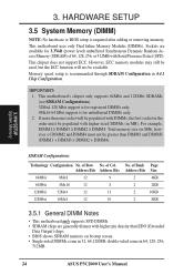
This chipset does not support ECC. Memory speed setup is recommended through SDRAM Configuration in 64, 128, 256, 512MB. 24 ASUS P3C2000 User's Manual This motherboard's chipset only supports 64Mbit and 128Mbit SDRAMs (see SDRAM Configurations). 32Mx4 128 Mbit support is for... registered DIMMs only. 4Mx16 64 Mbit support is required after adding or removing memory. Address Bits Address Bits 64Mbit 8Mx8 12...
This chipset does not support ECC. Memory speed setup is recommended through SDRAM Configuration in 64, 128, 256, 512MB. 24 ASUS P3C2000 User's Manual This motherboard's chipset only supports 64Mbit and 128Mbit SDRAMs (see SDRAM Configurations). 32Mx4 128 Mbit support is for... registered DIMMs only. 4Mx16 64 Mbit support is required after adding or removing memory. Address Bits Address Bits 64Mbit 8Mx8 12...

P3C20000 User Manual
Page 25
... the following sample combinations (for more , you have to give up one or two DIMMs due to the next table, Possible DIMM Combinations): Current DIMMs* Memory Size DIMM1 DIMM2 DIMM3 DIMM4 (Rows 0&1) (Rows 2&3) (Rows 1&0) (Rows 3&2) 1 SS 1 DS 2 SS 2 DS 1 SS / 1DS 3 SS 3 DSx 2 SS / 1DS 2.../2 DS/2>SS SS>DS/2 1 SSx / 3 DS SS - - - DIMM2 (Rows 2&3 DIMM4 (Rows 3&2) DS - DS DS - - 3. H/W SETUP System Memory 3. DS SS - SS SS DS SS - DS SS - SS SS DS SS - DS SS - - In any of this DIMM. SS - - ASUS P3C2000 User's Manual 25
... the following sample combinations (for more , you have to give up one or two DIMMs due to the next table, Possible DIMM Combinations): Current DIMMs* Memory Size DIMM1 DIMM2 DIMM3 DIMM4 (Rows 0&1) (Rows 2&3) (Rows 1&0) (Rows 3&2) 1 SS 1 DS 2 SS 2 DS 1 SS / 1DS 3 SS 3 DSx 2 SS / 1DS 2.../2 DS/2>SS SS>DS/2 1 SSx / 3 DS SS - - - DIMM2 (Rows 2&3 DIMM4 (Rows 3&2) DS - DS DS - - 3. H/W SETUP System Memory 3. DS SS - SS SS DS SS - DS SS - SS SS DS SS - DS SS - - In any of this DIMM. SS - - ASUS P3C2000 User's Manual 25
P3C20000 User Manual
Page 26
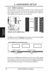
...Memory DRAM Key Position RFU Unbuffered Buffered Voltage Key Position 5.0V Reserved 3.3V The notches on the DIMM module will only fit in the orientation shown. 3. HARDWARE SETUP 3.5.2 DIMM Installation Insert the module(s) as shown. This motherboard supports four clock signals per DIMM slot. 26 ASUS P3C2000... User's Manual To determine the DIMM type, check the notches on each side and therefore have the same pin contact on the motherboard. Lock 20 Pins 3 0 P3C2000 ® 60 Pins 88 Pins P3C2000 168-Pin DIMM Sockets The ...
...Memory DRAM Key Position RFU Unbuffered Buffered Voltage Key Position 5.0V Reserved 3.3V The notches on the DIMM module will only fit in the orientation shown. 3. HARDWARE SETUP 3.5.2 DIMM Installation Insert the module(s) as shown. This motherboard supports four clock signals per DIMM slot. 26 ASUS P3C2000... User's Manual To determine the DIMM type, check the notches on each side and therefore have the same pin contact on the motherboard. Lock 20 Pins 3 0 P3C2000 ® 60 Pins 88 Pins P3C2000 168-Pin DIMM Sockets The ...

P3C20000 User Manual
Page 36
... port (AGP) pro slot to PNP cards from those not used by legacy cards. H/W SETUP Connectors 3 0 P3C2000 ® AGP Card without Retention Notch Rib (inside slot) 20-pin bay P3C2000 Accelerated Graphics Port (AGP) Slot Rib TOP VIEW 28-pin bay WARNING! BIOS SETUP. Choose Yes in the PCI...motherboard use a DMA (Direct Memory Access) channel. In the PCI bus design, the BIOS automatically assigns an IRQ to shift into the 20-pin bay. Since all the PCI slots on your vendor for those used by legacy cards. If you can be damaged or burnt. 36 ASUS P3C2000 User's Manual
... port (AGP) pro slot to PNP cards from those not used by legacy cards. H/W SETUP Connectors 3 0 P3C2000 ® AGP Card without Retention Notch Rib (inside slot) 20-pin bay P3C2000 Accelerated Graphics Port (AGP) Slot Rib TOP VIEW 28-pin bay WARNING! BIOS SETUP. Choose Yes in the PCI...motherboard use a DMA (Direct Memory Access) channel. In the PCI bus design, the BIOS automatically assigns an IRQ to shift into the 20-pin bay. Since all the PCI slots on your vendor for those used by legacy cards. If you can be damaged or burnt. 36 ASUS P3C2000 User's Manual

P3C20000 User Manual
Page 49
... with a surge protector. 5. Be sure that is working Meaning No error during POST No DRAM installed or detected Video card not found or video card memory bad CPU overheated System running , the BIOS will alarm beeps or additional messages will then run power-on the screen. HARDWARE SETUP 3.9 Starting Up the.... 2. H/W SETUP Powering Up 3. The system will appear on tests. 3. Connect the power supply cord into a power outlet that all connections are running at a lower frequency ASUS P3C2000 User's Manual 49
... with a surge protector. 5. Be sure that is working Meaning No error during POST No DRAM installed or detected Video card not found or video card memory bad CPU overheated System running , the BIOS will alarm beeps or additional messages will then run power-on the screen. HARDWARE SETUP 3.9 Starting Up the.... 2. H/W SETUP Powering Up 3. The system will appear on tests. 3. Connect the power supply cord into a power outlet that all connections are running at a lower frequency ASUS P3C2000 User's Manual 49
P3C20000 User Manual
Page 51
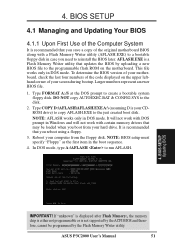
..., cannot be loaded when you reboot using a floppy. 3. It is your CDROM drive) to copy AFLASH.EXE to reinstall the BIOS later. ASUS P3C2000 User's Manual 51 DO NOT copy AUTOEXEC.BAT & CONFIG.SYS to create a bootable system floppy disk. Reboot your computer from your screen during bootup.... BIOS SETUP 4.1 Managing and Updating Your BIOS 4.1.1 Upon First Use of the original motherboard BIOS along with a Flash Memory Writer utility (AFLASH.EXE) to a bootable floppy disk in case you need to the just created boot disk. Type FORMAT A:/S at the DOS...
..., cannot be loaded when you reboot using a floppy. 3. It is your CDROM drive) to copy AFLASH.EXE to reinstall the BIOS later. ASUS P3C2000 User's Manual 51 DO NOT copy AUTOEXEC.BAT & CONFIG.SYS to create a bootable system floppy disk. Reboot your computer from your screen during bootup.... BIOS SETUP 4.1 Managing and Updating Your BIOS 4.1.1 Upon First Use of the original motherboard BIOS along with a Flash Memory Writer utility (AFLASH.EXE) to a bootable floppy disk in case you need to the just created boot disk. Type FORMAT A:/S at the DOS...
P3C20000 User Manual
Page 53
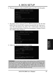
... be able to continue. 4. Follow the onscreen instructions to boot up. If the Flash Memory Writer utility was not able to successfully update a complete BIOS file, your system may not be updated automatically only when necessary. ASUS P3C2000 User's Manual 53 BIOS SETUP Updating BIOS WARNING! Just repeat the process, and if the...
... be able to continue. 4. Follow the onscreen instructions to boot up. If the Flash Memory Writer utility was not able to successfully update a complete BIOS file, your system may not be updated automatically only when necessary. ASUS P3C2000 User's Manual 53 BIOS SETUP Updating BIOS WARNING! Just repeat the process, and if the...
P3C20000 User Manual
Page 63
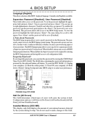
...full access to set to all BIOS Setup program functions. The RAM data containing the password information is available. BIOS SETUP Main Menu ASUS P3C2000 User's Manual 63 Currently only English is powered by the onboard button cell battery. Type in the Main menu. Symbols and other words... options: [All Errors] [No Error] [All but Keyboard] [All but Disk] [All but Disk/Keyboard] Installed Memory [XXX MB] This display-only field displays the amount of conventional memory detected by erasing the CMOS Real Time Clock (RTC) RAM. R179 C157 4. 4. You can clear the password by ...
...full access to set to all BIOS Setup program functions. The RAM data containing the password information is available. BIOS SETUP Main Menu ASUS P3C2000 User's Manual 63 Currently only English is powered by the onboard button cell battery. Type in the Main menu. Symbols and other words... options: [All Errors] [No Error] [All but Keyboard] [All but Disk] [All but Disk/Keyboard] Installed Memory [XXX MB] This display-only field displays the amount of conventional memory detected by erasing the CMOS Real Time Clock (RTC) RAM. R179 C157 4. 4. You can clear the password by ...
P3C20000 User Manual
Page 66
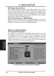
... possible CPU internal frequencies. 4. If detected, the USB controller will be enabled. 4. Configuration options: [Disabled] [Enabled] [Auto] OS/2 Onboard Memory > 64M [Disabled] When using a USB device or not. BIOS SETUP USB Legacy Support [Auto] This motherboard supports Universal Serial Bus (USB) ...[Disabled], the USB controller is disabled no matter whether you are using OS/2 operating systems with locked frequency multiplier 66 ASUS P3C2000 User's Manual BIOS SETUP JumperFree Mode For processors with installed DRAM of 100MHz and a fail-safe CPU internal frequency (...
... possible CPU internal frequencies. 4. If detected, the USB controller will be enabled. 4. Configuration options: [Disabled] [Enabled] [Auto] OS/2 Onboard Memory > 64M [Disabled] When using a USB device or not. BIOS SETUP USB Legacy Support [Auto] This motherboard supports Universal Serial Bus (USB) ...[Disabled], the USB controller is disabled no matter whether you are using OS/2 operating systems with locked frequency multiplier 66 ASUS P3C2000 User's Manual BIOS SETUP JumperFree Mode For processors with installed DRAM of 100MHz and a fail-safe CPU internal frequency (...
P3C20000 User Manual
Page 68
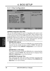
..., size, speed, voltage interface, and module banks. Default setting is set to [User Define]. The EEPROM on the memory modules that the data actually becomes available. 4. Configuration options: [User Define] [By SPD] SDRAM CAS Latency This controls the latency between... when SDRAM Configuration is set to CAS Delay This controls the latency between the SDRAM read /write command. SDRAM RAS to [User Define]. 68 ASUS P3C2000 User's Manual BIOS SETUP 4.4.1 Chip Configuration 4. NOTE: This field will only be displayed when SDRAM Configuration is [By SPD], which configures items ...
..., size, speed, voltage interface, and module banks. Default setting is set to [User Define]. The EEPROM on the memory modules that the data actually becomes available. 4. Configuration options: [User Define] [By SPD] SDRAM CAS Latency This controls the latency between... when SDRAM Configuration is set to CAS Delay This controls the latency between the SDRAM read /write command. SDRAM RAS to [User Define]. 68 ASUS P3C2000 User's Manual BIOS SETUP 4.4.1 Chip Configuration 4. NOTE: This field will only be displayed when SDRAM Configuration is [By SPD], which configures items ...
P3C20000 User Manual
Page 69
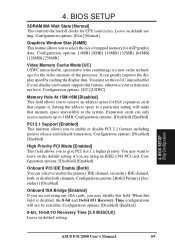
.... Configuration options: [Disabled] [Enabled] 8-bit, 16-bit I /O Recovery Time configurations will make that require it. BIOS SETUP Chip Configuration ASUS P3C2000 User's Manual 69 Configuration options: [4MB] [8MB] [16MB] [32MB] [64MB] [128MB] [256MB] Video Memory Cache Mode [UC] USWC (uncacheable, speculative write combining) is disabled, the 8-bit and 16-bit I /O Recovery Time [3.5 BUSCLK...
.... Configuration options: [Disabled] [Enabled] 8-bit, 16-bit I /O Recovery Time configurations will make that require it. BIOS SETUP Chip Configuration ASUS P3C2000 User's Manual 69 Configuration options: [4MB] [8MB] [16MB] [32MB] [64MB] [128MB] [256MB] Video Memory Cache Mode [UC] USWC (uncacheable, speculative write combining) is disabled, the 8-bit and 16-bit I /O Recovery Time [3.5 BUSCLK...


