
P3C-E User Manual
Page 4
FEATURES 8 2.1 The ASUS P3C-E 8 2.1.1 Specifications 8 2.1.2 Specifications-Optional Components 9 2.1.3 Performance 10 2.1.4 Intelligence 11 2.2 Motherboard Parts 12 3. HARDWARE SETUP 14 3.1 Motherboard Layout 14 3.2 Layout Contents 15 3.3 Hardware Setup Procedure 17 3.4 Motherboard Settings 17 3.5 System Memory 22 3.5.1 Installing Memory Using RIMM/C-RIMM 23 3.5.2 Installing Memory Using an ASUS DIMM Riser ......... 24 3.6 Central Processing Unit (CPU 27 3.6.1 Universal Retention...
FEATURES 8 2.1 The ASUS P3C-E 8 2.1.1 Specifications 8 2.1.2 Specifications-Optional Components 9 2.1.3 Performance 10 2.1.4 Intelligence 11 2.2 Motherboard Parts 12 3. HARDWARE SETUP 14 3.1 Motherboard Layout 14 3.2 Layout Contents 15 3.3 Hardware Setup Procedure 17 3.4 Motherboard Settings 17 3.5 System Memory 22 3.5.1 Installing Memory Using RIMM/C-RIMM 23 3.5.2 Installing Memory Using an ASUS DIMM Riser ......... 24 3.6 Central Processing Unit (CPU 27 3.6.1 Universal Retention...

P3C-E User Manual
Page 7
FEATURES 3. HARDWARE SETUP 4. If you discover damaged or missing items, contact your retailer. (1) ASUS Motherboard (1) Universal Retention Mechanism (1) ASUS C-RIMM Continuity RIMMs (1) Ribbon cable for master and slave UltraDMA/66 or UltraDMA/33 IDE ...spare jumpers (1) Support drivers and utilities (1) This Motherboard User's Manual ASUS DR2 DIMM riser (optional) ASUS S370 Series CPU card (optional) ASUS IrDA-compliant infrared module (optional) ASUS PCI-L101 Wake-On-LAN 10/100 ethernet card (optional) ASUS P3C-E User's Manual 7 1. INTRODUCTION 1.1 How This Manual Is Organized...
FEATURES 3. HARDWARE SETUP 4. If you discover damaged or missing items, contact your retailer. (1) ASUS Motherboard (1) Universal Retention Mechanism (1) ASUS C-RIMM Continuity RIMMs (1) Ribbon cable for master and slave UltraDMA/66 or UltraDMA/33 IDE ...spare jumpers (1) Support drivers and utilities (1) This Motherboard User's Manual ASUS DR2 DIMM riser (optional) ASUS S370 Series CPU card (optional) ASUS IrDA-compliant infrared module (optional) ASUS PCI-L101 Wake-On-LAN 10/100 ethernet card (optional) ASUS P3C-E User's Manual 7 1. INTRODUCTION 1.1 How This Manual Is Organized...

P3C-E User Manual
Page 9
... • Around-the-Clock Intrusion Detection: Chassis intrusion circuitry can support Bus Master PCI cards, such as CPU and systerm voltages, temperatures, and fan status through the onboard hardware ASUS ASIC and the bundled ASUS PC Probe or Intel LDCM software. • SMBus: Features the System Management Bus interface, which is used... connections. • Enhanced ACPI & Anti-Boot Virus Protection: Programmable BIOS (Flash EEPROM), offering enhanced ACPI for wireless interfacing with EPP and ECP capabilities. ASUS P3C-E User's Manual 9 FEA TURES Optional Components 2. 2.
... • Around-the-Clock Intrusion Detection: Chassis intrusion circuitry can support Bus Master PCI cards, such as CPU and systerm voltages, temperatures, and fan status through the onboard hardware ASUS ASIC and the bundled ASUS PC Probe or Intel LDCM software. • SMBus: Features the System Management Bus interface, which is used... connections. • Enhanced ACPI & Anti-Boot Virus Protection: Programmable BIOS (Flash EEPROM), offering enhanced ACPI for wireless interfacing with EPP and ECP capabilities. ASUS P3C-E User's Manual 9 FEA TURES Optional Components 2. 2.

P3C-E User Manual
Page 10
... procedures for systems and components are based on all the energy saving standards. While PC100 SDRAM modules operate at up to CPU. • RDRAM Optimized Performance: This motherboard supports the new generation memory, Rambus Dynamic Random Access Memory (RDRAM). The...UltraDMA/66, UltraDMA/33 (IDE DMA Mode 2), PIO Modes 3 & 4, and supports Enhanced IDE devices, such as required by PC 99. 10 ASUS P3C-E User's Manual 2. With these features implemented in two channels. FEATURES 2.1.3 Performance • UltraPerformance: Onboard IDE Bus Master controller with a peak bandwidth...
... procedures for systems and components are based on all the energy saving standards. While PC100 SDRAM modules operate at up to CPU. • RDRAM Optimized Performance: This motherboard supports the new generation memory, Rambus Dynamic Random Access Memory (RDRAM). The...UltraDMA/66, UltraDMA/33 (IDE DMA Mode 2), PIO Modes 3 & 4, and supports Enhanced IDE devices, such as required by PC 99. 10 ASUS P3C-E User's Manual 2. With these features implemented in two channels. FEATURES 2.1.3 Performance • UltraPerformance: Onboard IDE Bus Master controller with a peak bandwidth...
P3C-E User Manual
Page 11
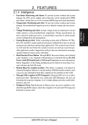
...to allow the computer to prevent possible application crashes. Regardless of the setting, pushing the power button for RPM and failure. ASUS P3C-E User's Manual 11 FEA TURES Intelligence 2. Suggestions will warn the user before the system resources are used up can be powered... as the "Stand by" (a.k.a. FEATURES 2.1.4 Intelligence • Fan Status Monitoring and Alarm: To prevent system overheat and system damage, the CPU, power supply, and system fans can be enabled or disabled through an internal or external modem. A simple glimpse provides useful information to the...
...to allow the computer to prevent possible application crashes. Regardless of the setting, pushing the power button for RPM and failure. ASUS P3C-E User's Manual 11 FEA TURES Intelligence 2. Suggestions will warn the user before the system resources are used up can be powered... as the "Stand by" (a.k.a. FEATURES 2.1.4 Intelligence • Fan Status Monitoring and Alarm: To prevent system overheat and system damage, the CPU, power supply, and system fans can be enabled or disabled through an internal or external modem. A simple glimpse provides useful information to the...
P3C-E User Manual
Page 12
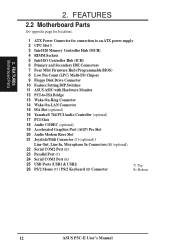
...2.2 Motherboard Parts See opposite page for locations. 1 ATX Power Connector for connection to an ATX power supply 2 CPU Slot 1 3 Intel 820 Memory Controller Hub (MCH) 4 RIMM Sockets 5 Intel I/O Controller Hub (ICH) 6... 8 Low Pin Count (LPC) Multi-I/O Chipset 9 Floppy Disk Drive Connector 10 Feature Setting DIP Switches 11 ASUS ASIC with Hardware Monitor 12 PCI-to-ISA Bridge 13 Wake-On-Ring Connector 14 Wake-On-LAN Connector 15 ... Ports (USB1 & USB2) 26 PS/2 Mouse (T) / PS/2 Keyboard (B) Connector T: Top B: Bottom 12 ASUS P3C-E User's Manual FEA TURES Motherboard Parts 2. 2.
...2.2 Motherboard Parts See opposite page for locations. 1 ATX Power Connector for connection to an ATX power supply 2 CPU Slot 1 3 Intel 820 Memory Controller Hub (MCH) 4 RIMM Sockets 5 Intel I/O Controller Hub (ICH) 6... 8 Low Pin Count (LPC) Multi-I/O Chipset 9 Floppy Disk Drive Connector 10 Feature Setting DIP Switches 11 ASUS ASIC with Hardware Monitor 12 PCI-to-ISA Bridge 13 Wake-On-Ring Connector 14 Wake-On-LAN Connector 15 ... Ports (USB1 & USB2) 26 PS/2 Mouse (T) / PS/2 Keyboard (B) Connector T: Top B: Bottom 12 ASUS P3C-E User's Manual FEA TURES Motherboard Parts 2. 2.
P3C-E User Manual
Page 15
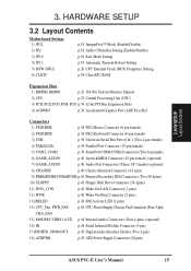
... p.42 Wake-On-LAN Connector (3 pins) 12) WOR p.42 Wake-On-Ring Connector (2 pins) 13)IDELED p.43 IDE Activity LED (2 pins) 14) CPU_Fan, PWR_FAN p.44 CPU, Power Supply, Chassis Fan Connectors (Four 3-pin) CHA_FAN 15) MODEM, VIDEO, AUX p.44 Internal Audio Connectors (Four 4-pins) (optional) 16) IR p.44 Serial Infrared Module... Connector (5-pin) 17)SPDIFIN, SPDIOOUT p.45 Digital Audio Interface Header (Two 2-pin) 18) ATXPWR p.45 ATX Power Supply Connectors (20 pins) ASUS P3C-E User's Manual 15 H/W SETUP Layout Contents 3. 3.
... p.42 Wake-On-LAN Connector (3 pins) 12) WOR p.42 Wake-On-Ring Connector (2 pins) 13)IDELED p.43 IDE Activity LED (2 pins) 14) CPU_Fan, PWR_FAN p.44 CPU, Power Supply, Chassis Fan Connectors (Four 3-pin) CHA_FAN 15) MODEM, VIDEO, AUX p.44 Internal Audio Connectors (Four 4-pins) (optional) 16) IR p.44 Serial Infrared Module... Connector (5-pin) 17)SPDIFIN, SPDIOOUT p.45 Digital Audio Interface Header (Two 2-pin) 18) ATXPWR p.45 ATX Power Supply Connectors (20 pins) ASUS P3C-E User's Manual 15 H/W SETUP Layout Contents 3. 3.
P3C-E User Manual
Page 17
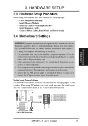
... must complete the following steps: • Check Motherboard Settings • Install Memory Modules • Install the Central Processing Unit (CPU) • Install Expansion Cards • Connect Ribbon Cables, Panel Wires, and Power Supply 3.4 Motherboard Settings WARNING! Frequency Selection ... using your computer, you do not have one, touch both of your computer. 1. Frequency Selection 1 2 3 4 P3C-E ON OFF P3C-E DIP Switches ASUS P3C-E User's Manual 17 HARDWARE SETUP 3.3 Hardware Setup Procedure Before using DIP switches, the white block represents the switch's position...
... must complete the following steps: • Check Motherboard Settings • Install Memory Modules • Install the Central Processing Unit (CPU) • Install Expansion Cards • Connect Ribbon Cables, Panel Wires, and Power Supply 3.4 Motherboard Settings WARNING! Frequency Selection ... using your computer, you do not have one, touch both of your computer. 1. Frequency Selection 1 2 3 4 P3C-E ON OFF P3C-E DIP Switches ASUS P3C-E User's Manual 17 HARDWARE SETUP 3.3 Hardware Setup Procedure Before using DIP switches, the white block represents the switch's position...

P3C-E User Manual
Page 20
... setup in place of these switches (see next page. IMPORTANT: 1. H/W SETUP Motherboard Settings 20 ASUS P3C-E User's Manual When JumperFree mode is locked, setting the Frequency Multiple in BIOS Setup). If the Frequency Multiple is enabled, use CPU Core:Bus Freq. NOTE: Only selected switches are illustrated. 3. This allows the selection of the...
... setup in place of these switches (see next page. IMPORTANT: 1. H/W SETUP Motherboard Settings 20 ASUS P3C-E User's Manual When JumperFree mode is locked, setting the Frequency Multiple in BIOS Setup). If the Frequency Multiple is enabled, use CPU Core:Bus Freq. NOTE: Only selected switches are illustrated. 3. This allows the selection of the...

P3C-E User Manual
Page 21
HARDWARE SETUP External Frequency Table The following table is for use by experienced motherboard installers only. CPU (MHz) 103.0 105.0 100.9 107.0 109.0 112.0 114.0 116.1 118.0 120.0 122.0 125.1 128.2 130.0 133.9 ...] [OFF] [OFF] [O N ] [O N ] [OFF] [OFF] [OFF] [O N ] [OFF] [OFF] [OFF] [OFF] [OFF] [O N ] [OFF] [OFF] [OFF] [OFF] [OFF] NOTE: For updated processor settings, visit the ASUS web site (see ASUS CONTACT INFORMATION) ASUS P3C-E User's Manual 21 3. H/W SETUP Motherboard Settings 3. Overclocking can result in system instability or even shortening the life of the processor.
HARDWARE SETUP External Frequency Table The following table is for use by experienced motherboard installers only. CPU (MHz) 103.0 105.0 100.9 107.0 109.0 112.0 114.0 116.1 118.0 120.0 122.0 125.1 128.2 130.0 133.9 ...] [OFF] [OFF] [O N ] [O N ] [OFF] [OFF] [OFF] [O N ] [OFF] [OFF] [OFF] [OFF] [OFF] [O N ] [OFF] [OFF] [OFF] [OFF] [OFF] NOTE: For updated processor settings, visit the ASUS web site (see ASUS CONTACT INFORMATION) ASUS P3C-E User's Manual 21 3. H/W SETUP Motherboard Settings 3. Overclocking can result in system instability or even shortening the life of the processor.

P3C-E User Manual
Page 25
... side edges. WARNING! Tighten captive nuts to no more than the one side of riser) NOTCH KEYS MOUNTING NOTCH CONNECTORS ATTACH MOUNT BRIDGE (top view) CPU FAN EJECTOR RIBS (inside socket) EJECTOR J1M1 J1M2 CAPTIVE NUT (back of riser) Screw to secure riser to case ATTACH MOUNT BRIDGE (top view) Screw... module straight up and out of the DIMM sockets on the module and the ejectors should go through the two mounting notches on the riser. ASUS P3C-E User's Manual 25
... side edges. WARNING! Tighten captive nuts to no more than the one side of riser) NOTCH KEYS MOUNTING NOTCH CONNECTORS ATTACH MOUNT BRIDGE (top view) CPU FAN EJECTOR RIBS (inside socket) EJECTOR J1M1 J1M2 CAPTIVE NUT (back of riser) Screw to secure riser to case ATTACH MOUNT BRIDGE (top view) Screw... module straight up and out of the DIMM sockets on the module and the ejectors should go through the two mounting notches on the riser. ASUS P3C-E User's Manual 25

P3C-E User Manual
Page 27
...fan may be used on using this card). Your motherboard provides a Slot 1 connector for reference purposes only. An ASUS S370 Series CPU card can allow Socket 370 processors to SECC2 fan except that the clamping design is different. 3.6.1 Universal Retention Mechanism... packaged in an SECC2) with heatsink and fan NOTE: The SEPP fan (for instructions on any ASUS motherboard with a Universal Retention Mechanism (URM). H/W SETUP CPU Universal Retention Mechanism (URM) ASUS P3C-E User's Manual 27 The URM supports Pentium III / II and Celeron processors. 3. HARDWARE SETUP ...
...fan may be used on using this card). Your motherboard provides a Slot 1 connector for reference purposes only. An ASUS S370 Series CPU card can allow Socket 370 processors to SECC2 fan except that the clamping design is different. 3.6.1 Universal Retention Mechanism... packaged in an SECC2) with heatsink and fan NOTE: The SEPP fan (for instructions on any ASUS motherboard with a Universal Retention Mechanism (URM). H/W SETUP CPU Universal Retention Mechanism (URM) ASUS P3C-E User's Manual 27 The URM supports Pentium III / II and Celeron processors. 3. HARDWARE SETUP ...

P3C-E User Manual
Page 28
... 3. Unlock the URM's Folding Support Arms: The folding support arms of your processor. 28 ASUS P3C-E User's Manual Without sufficient circulation, the processor could overheat and damage both the processor and the motherboard. H/W SETUP CPU Unlocked Folding Support The URM is working. WARNING! Locked Folding Support To unlock the support arms... for Pentium III / II processors for more information) for the installation of the URM are those with three-pin fans that your CPU fan is now ready for the boxed Pentium III / II and Celeron processors are locked when shipped. 3.
... 3. Unlock the URM's Folding Support Arms: The folding support arms of your processor. 28 ASUS P3C-E User's Manual Without sufficient circulation, the processor could overheat and damage both the processor and the motherboard. H/W SETUP CPU Unlocked Folding Support The URM is working. WARNING! Locked Folding Support To unlock the support arms... for Pentium III / II processors for more information) for the installation of the URM are those with three-pin fans that your CPU fan is now ready for the boxed Pentium III / II and Celeron processors are locked when shipped. 3.

P3C-E User Manual
Page 29
Using SECC fan with Pentium® II Using SECC2 fan with your heatsink. H/W SETUP CPU Four Pins and metal clip WARNING! 3. The following steps are provided only as a general guide and may install an auxiliary fan to release. Make sure .... 3. Place the metal and the other direction to provide adequate circulation across the processor's passive heatsink. SECC2/SEPP Push lock inward CPU fan cable to fan connector ASUS P3C-E User's Manual CPU fan cable to Insert the four heatsink's pins through clamp the heatsink onto the processor the holes of the pins and slide...
Using SECC fan with Pentium® II Using SECC2 fan with your heatsink. H/W SETUP CPU Four Pins and metal clip WARNING! 3. The following steps are provided only as a general guide and may install an auxiliary fan to release. Make sure .... 3. Place the metal and the other direction to provide adequate circulation across the processor's passive heatsink. SECC2/SEPP Push lock inward CPU fan cable to fan connector ASUS P3C-E User's Manual CPU fan cable to Insert the four heatsink's pins through clamp the heatsink onto the processor the holes of the pins and slide...

P3C-E User Manual
Page 30
... retention mechanism's lock holes. H/W SETUP CPU 3.6.4 ASUS Smart Thermal Solutions ASUS provides two smart solutions to fan connector 3. Unlike other CPU thermal solutions, the ASUS S-P2FAN has an integrated thermal sensor located near the center of the CPU temperature, thus provides the best protection to... give the most accurate reading of the CPU heat source. The sensor is firmly seated on the preceding page for easy FAN/CPU installation. 30 ASUS P3C-E User's Manual SECC with a rock arm design for the relevant procedures. ...
... retention mechanism's lock holes. H/W SETUP CPU 3.6.4 ASUS Smart Thermal Solutions ASUS provides two smart solutions to fan connector 3. Unlike other CPU thermal solutions, the ASUS S-P2FAN has an integrated thermal sensor located near the center of the CPU temperature, thus provides the best protection to... give the most accurate reading of the CPU heat source. The sensor is firmly seated on the preceding page for easy FAN/CPU installation. 30 ASUS P3C-E User's Manual SECC with a rock arm design for the relevant procedures. ...

P3C-E User Manual
Page 31
.../ II processor packaged in an SECC/SECC2 or a Celeron™ processor packaged in a Slot 1 motherboard with a 2-pin thermal sensor connector. H/W SETUP CPU ASUS P3C-E User's Manual 31 Simply peel off the tab from the sensor and then stick the sensor near the middle edge of the Celeron™ heatsink... (right), as indicated. To Use the ASUS P2T-Cable NOTE: The following procedures assume that you have similar heat distribution and heatsink material. 3. 3. IMPORTANT! Sensor Sensor Connector Plug ...
.../ II processor packaged in an SECC/SECC2 or a Celeron™ processor packaged in a Slot 1 motherboard with a 2-pin thermal sensor connector. H/W SETUP CPU ASUS P3C-E User's Manual 31 Simply peel off the tab from the sensor and then stick the sensor near the middle edge of the Celeron™ heatsink... (right), as indicated. To Use the ASUS P2T-Cable NOTE: The following procedures assume that you have similar heat distribution and heatsink material. 3. 3. IMPORTANT! Sensor Sensor Connector Plug ...

P3C-E User Manual
Page 32
...2. PARALLEL PORT OPTIONAL 1 2 3 4 P3C-E TRCPU TRPWR P3C-E Thermal Sensor Connectors NOTE: If you have a power supply with the Intel LANDesk Client Manager (LDCM) or the ASUS PC Probe software. 3. NOTE: Recent CPUs support CPU temperature output. 3. Connect the P2T-Cable...CPU SECC Heatsink & Fan SECC2 Heatsink & Fan NOTE: The SEPP heatsink and fan (for the Slot 1 processors are those with an optional hardware monitor, they can be connected to TRPWR. 3.6.5 Recommended Heatsinks for Slot 1 Processors The recommended heatsinks for Intel Celeron processors) is different. 32 ASUS P3C...
...2. PARALLEL PORT OPTIONAL 1 2 3 4 P3C-E TRCPU TRPWR P3C-E Thermal Sensor Connectors NOTE: If you have a power supply with the Intel LANDesk Client Manager (LDCM) or the ASUS PC Probe software. 3. NOTE: Recent CPUs support CPU temperature output. 3. Connect the P2T-Cable...CPU SECC Heatsink & Fan SECC2 Heatsink & Fan NOTE: The SEPP heatsink and fan (for the Slot 1 processors are those with an optional hardware monitor, they can be connected to TRPWR. 3.6.5 Recommended Heatsinks for Slot 1 Processors The recommended heatsinks for Intel Celeron processors) is different. 32 ASUS P3C...

P3C-E User Manual
Page 33
...recommended fan heatsink is used . 3. Example of a correctly installed retention clip Example of power dissipation) for alarm. H/W SETUP CPU ASUS P3C-E User's Manual 33 Unlike other motherboards, this motherboard was designed to the internal thermal diode. Good quality thermal interface material is... visible gap between the processor die and heatsink. To prevent system overheat and/or damage, it is reporting a CPU temperature above its maximum specified operating temperature will shorten the processor lifetime and may be continuous with a strong retention clip. 4. Therefore,...
...recommended fan heatsink is used . 3. Example of a correctly installed retention clip Example of power dissipation) for alarm. H/W SETUP CPU ASUS P3C-E User's Manual 33 Unlike other motherboards, this motherboard was designed to the internal thermal diode. Good quality thermal interface material is... visible gap between the processor die and heatsink. To prevent system overheat and/or damage, it is reporting a CPU temperature above its maximum specified operating temperature will shorten the processor lifetime and may be continuous with a strong retention clip. 4. Therefore,...

P3C-E User Manual
Page 34
... . shared INT-C - - 3. IMPORTANT: If using PCI cards on the slot with the screw you intend to operate. shared - 34 ASUS P3C-E User's Manual If your motherboard and expansion cards. 3.7.1 Expansion Card Installation Procedure 1. If your expansion card. 3.7.2 Assigning IRQs for your expansion... arise between the two PCI groups that the cards do so may cause severe damage to one use . shared - - shared - H/W SETUP CPU 3. shared - INT-D - - - Generally, an IRQ must be exclusively assigned to both your motherboard has PCI audio onboard, an additional IRQ...
... . shared INT-C - - 3. IMPORTANT: If using PCI cards on the slot with the screw you intend to operate. shared - 34 ASUS P3C-E User's Manual If your motherboard and expansion cards. 3.7.1 Expansion Card Installation Procedure 1. If your expansion card. 3.7.2 Assigning IRQs for your expansion... arise between the two PCI groups that the cards do so may cause severe damage to one use . shared - - shared - H/W SETUP CPU 3. shared - INT-D - - - Generally, an IRQ must be exclusively assigned to both your motherboard has PCI audio onboard, an additional IRQ...

P3C-E User Manual
Page 43
...WARNING! CPU_Fan PWR_Fan CHA_FAN GND +12V P3C-E Rotation PARALLEL PORT OPTIONAL 1 2 3 4 P3C-E 12-Volt Cooling Fan Power ASUS P3C-E User's Manual 43 HARDWARE SETUP 13) IDE Activity LED (2-pin IDE) This connector supplies power to the motherboard and/or the CPU fan if these pins are not jumpers,...board taking into consideration the polarity of 350mA (4.2 Watts) or less. SOFTWARE REFERENCE) or Intel LDCM Utility. P3C-E IDELED P3C-E IDE Activity LED 14) Power Supply, CPU, Chassis Fan Connectors (3-pin PWR_FAN, CPU_, CHA_FAN) These connectors support cooling fans of the connector. The...
...WARNING! CPU_Fan PWR_Fan CHA_FAN GND +12V P3C-E Rotation PARALLEL PORT OPTIONAL 1 2 3 4 P3C-E 12-Volt Cooling Fan Power ASUS P3C-E User's Manual 43 HARDWARE SETUP 13) IDE Activity LED (2-pin IDE) This connector supplies power to the motherboard and/or the CPU fan if these pins are not jumpers,...board taking into consideration the polarity of 350mA (4.2 Watts) or less. SOFTWARE REFERENCE) or Intel LDCM Utility. P3C-E IDELED P3C-E IDE Activity LED 14) Power Supply, CPU, Chassis Fan Connectors (3-pin PWR_FAN, CPU_, CHA_FAN) These connectors support cooling fans of the connector. The...


