P2L97 User Manual
Page 1
R P2L97 Pentium® II Motherboard USER'S MANUAL
R P2L97 Pentium® II Motherboard USER'S MANUAL
P2L97 User Manual
Page 4
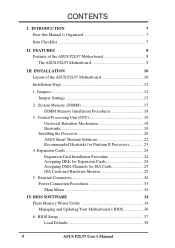
... for Pentium II Processors 23 4. Jumpers 12 Jumper Settings 13 2. INSTALLATION 10 Layout of the ASUS P2L97 Motherboard 8 The ASUS P2L97 Motherboard 9 III. BIOS SOFTWARE 34 Flash Memory Writer Utility 34 Managing and Updating Your Motherboard's BIOS 36 6. FEATURES 8 Features of the ASUS P2L97 Motherboard 10 Installation Steps 12 1. System Memory (DIMM 17 DIMM Memory Installation Procedures 18 3. External Connectors...
... for Pentium II Processors 23 4. Jumpers 12 Jumper Settings 13 2. INSTALLATION 10 Layout of the ASUS P2L97 Motherboard 8 The ASUS P2L97 Motherboard 9 III. BIOS SOFTWARE 34 Flash Memory Writer Utility 34 Managing and Updating Your Motherboard's BIOS 36 6. FEATURES 8 Features of the ASUS P2L97 Motherboard 10 Installation Steps 12 1. System Memory (DIMM 17 DIMM Memory Installation Procedures 18 3. External Connectors...

P2L97 User Manual
Page 7
INTRODUCTION How this product Instructions on setting up the motherboard and jumper Instructions on setting up the BIOS software Item Checklist Check that your retailer. (1) ASUS Motherboard (1) Univeral retention mechanism for SECC/SECC2/SEPP (1) IDE ribbon cable for master and ...ribbon cable (1) Bag of spare jumper caps (1) Support CD with drivers and utilities (1) Motherboard user's manual Infrared module (optional) ASUS PCI-SC200 Fast-SCSI or PCI-SC860 Ultra-Fast SCSI card (optional) ASUS P2L97 User's Manual 7 I . Installation: IV. Features: III. INTRODUCTION (Manual / Checklist)...
INTRODUCTION How this product Instructions on setting up the motherboard and jumper Instructions on setting up the BIOS software Item Checklist Check that your retailer. (1) ASUS Motherboard (1) Univeral retention mechanism for SECC/SECC2/SEPP (1) IDE ribbon cable for master and ...ribbon cable (1) Bag of spare jumper caps (1) Support CD with drivers and utilities (1) Motherboard user's manual Infrared module (optional) ASUS PCI-SC200 Fast-SCSI or PCI-SC860 Ultra-Fast SCSI card (optional) ASUS P2L97 User's Manual 7 I . Installation: IV. Features: III. INTRODUCTION (Manual / Checklist)...
P2L97 User Manual
Page 8
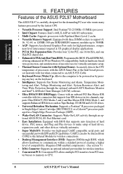
... of hard drives, PS/2 mouse, and Plug and Play devices to CPU. 8 ASUS P2L97 User's Manual II. FEATURES (Specifications) II. FEATURES Features of the ASUS P2L97 Motherboard The ASUS P2L97 is carefully designed for the demanding PC user who wants many features processed by the fastest... Connector: Supports an optional infrared port module for wireless connections. • Desktop Management Interface (DMI): Supports DMI through an optional ASUS PCI-L101 Fast Ethernet card. • Easy Installation: Equipped with BIOS that supports auto detection of hard drives, expansion cards, ...
... of hard drives, PS/2 mouse, and Plug and Play devices to CPU. 8 ASUS P2L97 User's Manual II. FEATURES (Specifications) II. FEATURES Features of the ASUS P2L97 Motherboard The ASUS P2L97 is carefully designed for the demanding PC user who wants many features processed by the fastest... Connector: Supports an optional infrared port module for wireless connections. • Desktop Management Interface (DMI): Supports DMI through an optional ASUS PCI-L101 Fast Ethernet card. • Easy Installation: Equipped with BIOS that supports auto detection of hard drives, expansion cards, ...

P2L97 User Manual
Page 9
II. FEATURES The ASUS P2L97 Motherboard T: PS/2 Mouse B: PS/2 Keyboard T: USB Port 1 B: USB Port 2 B: COM 1 T: Parallel B: Serial B: COM 2 Intel 440LX AGPset 3 DIMM Sockets Accelerated Graphics Port 4 PCI Slots Programmable Flash ROM 1 ISA/PCI Share 1 ISA Slot ASUS P2L97 User's Manual 9 FEATURES (Motherboard Parts) II.
II. FEATURES The ASUS P2L97 Motherboard T: PS/2 Mouse B: PS/2 Keyboard T: USB Port 1 B: USB Port 2 B: COM 1 T: Parallel B: Serial B: COM 2 Intel 440LX AGPset 3 DIMM Sockets Accelerated Graphics Port 4 PCI Slots Programmable Flash ROM 1 ISA/PCI Share 1 ISA Slot ASUS P2L97 User's Manual 9 FEATURES (Motherboard Parts) II.
P2L97 User Manual
Page 10
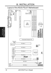
INSTALLATION Layout of the ASUS P2L97 Motherboard PS/2 Top: Mouse Bottom: Keyboard KB_UP Top: USB USB 1 Bottom: USB 2 PWR_FAN CPU_FAN JP1 Pentium II Thermal Sensor Connector COM 1 Parallel Port COM 2 Intel 440LX ... Slot 1 ISA Slot 2 BUS FREQ FS0 FS1 FS2 Intel PIIX4 PCIset CHA_FAN BF0 BF2 BF1 BF3 BUS FREQ IR Connector IDE LED Panel Connectors 10 ASUS P2L97 User's Manual
INSTALLATION Layout of the ASUS P2L97 Motherboard PS/2 Top: Mouse Bottom: Keyboard KB_UP Top: USB USB 1 Bottom: USB 2 PWR_FAN CPU_FAN JP1 Pentium II Thermal Sensor Connector COM 1 Parallel Port COM 2 Intel 440LX ... Slot 1 ISA Slot 2 BUS FREQ FS0 FS1 FS2 Intel PIIX4 PCIset CHA_FAN BF0 BF2 BF1 BF3 BUS FREQ IR Connector IDE LED Panel Connectors 10 ASUS P2L97 User's Manual
P2L97 User Manual
Page 11
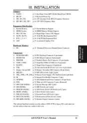
ASUS P2L97 User's Manual 11 INSTALLATION Jumpers 1) CLRTC 2) KB_UP 3) FS0, FS1, FS2 4) BF0, BF1, BF2, BF3 p. 13 Real Time Clock (RTC) RAM (Short/Clear CMOS) p. 13 Keyboard ...) 9) CHA_, PWR_, CPU_FAN p. 29 Chassis, Power Supply, CPU Fan Power Lead (3-pin block) 10) IR p. 30 Infrared Port Module Connector (5 pins) 11) ATXPWR p. 30 ATX Motherboard Power Connector (20-pin block) 12) WOL p. 31 Wake on LAN Connector (3 pins) (Reserved) 13) MSG LED (PANEL) p. 32 System Message LED (2 pins) 14) SMI...
ASUS P2L97 User's Manual 11 INSTALLATION Jumpers 1) CLRTC 2) KB_UP 3) FS0, FS1, FS2 4) BF0, BF1, BF2, BF3 p. 13 Real Time Clock (RTC) RAM (Short/Clear CMOS) p. 13 Keyboard ...) 9) CHA_, PWR_, CPU_FAN p. 29 Chassis, Power Supply, CPU Fan Power Lead (3-pin block) 10) IR p. 30 Infrared Port Module Connector (5 pins) 11) ATXPWR p. 30 ATX Motherboard Power Connector (20-pin block) 12) WOL p. 31 Wake on LAN Connector (3 pins) (Reserved) 13) MSG LED (PANEL) p. 32 System Message LED (2 pins) 14) SMI...
P2L97 User Manual
Page 12
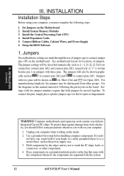
... (IC) chips. Setup the BIOS Software 1. Jumpers Several hardware settings are separated from the system. 12 ASUS P2L97 User's Manual A "1" is written besides pin 1 on the motherboard. Jumpers with three pins. For manufacturing simplicity, the jumpers may be moved together. To connect the pins,... work on your computer when working on the board. Install Expansion Cards 5. Place components on a grounded antistatic pad or on the Motherboard 2. Connect Ribbon Cables, Cabinet Wires, and Power Supply 6. The jumpers will be shown graphi- Unplug your computer. 1. Use the...
... (IC) chips. Setup the BIOS Software 1. Jumpers Several hardware settings are separated from the system. 12 ASUS P2L97 User's Manual A "1" is written besides pin 1 on the motherboard. Jumpers with three pins. For manufacturing simplicity, the jumpers may be moved together. To connect the pins,... work on your computer when working on the board. Install Expansion Cards 5. Place components on a grounded antistatic pad or on the Motherboard 2. Connect Ribbon Cables, Cabinet Wires, and Power Supply 6. The jumpers will be shown graphi- Unplug your computer. 1. Use the...
P2L97 User Manual
Page 17
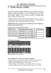
...form a memory size between 8MB to 384MB. ASUS P2L97 User's Manual 17 System Memory (DIMM) Only Dual Inline Memory Modules (DIMM) can be used with higher pin density than EDO chips. • BIOS shows EDO or SDRAM memory on the motherboard. INSTALLATION (System Memory) SDRAM DIMM (8 chips,...Single-sided DIMMs come in 16 or 64 MB, double-sided come in the BIOS Chipset Features Setup. Sockets are generally thinner with this motherboard. IMPORTANT: Memory speed setup is required through "Auto Configuration" in any combination as follows: DIMM Location 168-pin DIMM Memory Modules Total...
...form a memory size between 8MB to 384MB. ASUS P2L97 User's Manual 17 System Memory (DIMM) Only Dual Inline Memory Modules (DIMM) can be used with higher pin density than EDO chips. • BIOS shows EDO or SDRAM memory on the motherboard. INSTALLATION (System Memory) SDRAM DIMM (8 chips,...Single-sided DIMMs come in 16 or 64 MB, double-sided come in the BIOS Chipset Features Setup. Sockets are generally thinner with this motherboard. IMPORTANT: Memory speed setup is required through "Auto Configuration" in any combination as follows: DIMM Location 168-pin DIMM Memory Modules Total...

P2L97 User Manual
Page 18
...Pin DIMM Notch Key Definitions (3.3V) DRAM Key Position RFU Unbuffered Buffered Voltage Key Position 5.0V Reserved 3.3V The notch on the motherboard. You must be inserted into the DIMM slot on the DIMM module will only fit in the orientation as shown. DRAM SIMM modules... Output (EDO) . SDRAM DIMM modules have different pint contact on each side and therefore have the same pin contact on this motherboard. 18 ASUS P2L97 User's Manual INSTALLATION DIMM Memory Installation Procedures: Insert the module(s) as shown. Four clock signals are different on either side of ...
...Pin DIMM Notch Key Definitions (3.3V) DRAM Key Position RFU Unbuffered Buffered Voltage Key Position 5.0V Reserved 3.3V The notch on the motherboard. You must be inserted into the DIMM slot on the DIMM module will only fit in the orientation as shown. DRAM SIMM modules... Output (EDO) . SDRAM DIMM modules have different pint contact on each side and therefore have the same pin contact on this motherboard. 18 ASUS P2L97 User's Manual INSTALLATION DIMM Memory Installation Procedures: Insert the module(s) as shown. Four clock signals are different on either side of ...

P2L97 User Manual
Page 19
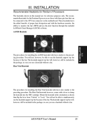
...processors are those with a Universal Retention Mechanism (URM). INSTALLATION CPU Universal Retention Mechanism (URM) Heatsinks The recommended heatsinks (see section on the motherboard. The URM supports Pentium II and Celeron processors. III. You may install an auxiliary fan, if necessary. Be sure that there is ...Cartridge (SECC/SECC2) or a Celeron™ processor packaged in an SEPP with heatsink and fan (top view) Universal Retention Mechanism Your motherboard comes preinstalled with three-pin fans that your CPU fan is working. ASUS P2L97 User's Manual 19 WARNING! III.
...processors are those with a Universal Retention Mechanism (URM). INSTALLATION CPU Universal Retention Mechanism (URM) Heatsinks The recommended heatsinks (see section on the motherboard. The URM supports Pentium II and Celeron processors. III. You may install an auxiliary fan, if necessary. Be sure that there is ...Cartridge (SECC/SECC2) or a Celeron™ processor packaged in an SEPP with heatsink and fan (top view) Universal Retention Mechanism Your motherboard comes preinstalled with three-pin fans that your CPU fan is working. ASUS P2L97 User's Manual 19 WARNING! III.
P2L97 User Manual
Page 21
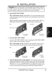
...information on the Slot 1 connector. III. With the heatsink facing the motherboard's chipset, push the SECC, SECC2, or SEPP gently but firmly into the Slot 1 connector until it is firmly seated on ASUS Smart Thermal Solutions.) ASUS P2L97 User's Manual 21 Secure the SECC/SECC2/SEPP Secure the SECC/SECC2/... shows the locks in the outward position and inward in place by pushing the SECC/SECC2/SEPP until you purchased the especially designed ASUS Smart Fan (ASUS S-P2FAN), which comes with Pentium® II only: The SECC locks should be outward when secured so that the lock shows ...
...information on the Slot 1 connector. III. With the heatsink facing the motherboard's chipset, push the SECC, SECC2, or SEPP gently but firmly into the Slot 1 connector until it is firmly seated on ASUS Smart Thermal Solutions.) ASUS P2L97 User's Manual 21 Secure the SECC/SECC2/SEPP Secure the SECC/SECC2/... shows the locks in the outward position and inward in place by pushing the SECC/SECC2/SEPP until you purchased the especially designed ASUS Smart Fan (ASUS S-P2FAN), which comes with Pentium® II only: The SECC locks should be outward when secured so that the lock shows ...
P2L97 User Manual
Page 23
... support top bar will not, however, be included in the package, in this manual are those with a lever to the CPU fan connector on the motherboard. ASUS P2L97 User's Manual 23
... support top bar will not, however, be included in the package, in this manual are those with a lever to the CPU fan connector on the motherboard. ASUS P2L97 User's Manual 23

P2L97 User Manual
Page 24
... Diagnostics (MSD.EXE) utility located in use . 3. Install the necessary software drivers for possible future use at the same time. 24 ASUS P2L97 User's Manual Currently, there are in the Windows directory to both your computer system's cover and the bracket plate on the slot you... you intend to use Windows 95, the Resources tab under the Control Panel program). INSTALLATION Expansion Cards III. INSTALLATION 4. If your motherboard has audio onboard, an extra 3 IRQs will experience problems when those two devices are two types of your power supply when adding ...
... Diagnostics (MSD.EXE) utility located in use . 3. Install the necessary software drivers for possible future use at the same time. 24 ASUS P2L97 User's Manual Currently, there are in the Windows directory to both your computer system's cover and the bracket plate on the slot you... you intend to use Windows 95, the Resources tab under the Control Panel program). INSTALLATION Expansion Cards III. INSTALLATION 4. If your motherboard has audio onboard, an extra 3 IRQs will experience problems when those two devices are two types of your power supply when adding ...
P2L97 User Manual
Page 25
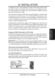
... requiring an IRQ. IMPORTANT: To avoid conflicts, reserve the necessary IRQs and DMAs for an ISA Configuration Utility. R P2L97 Accelerated Graphics Port (AGP) ASUS P2L97 User's Manual 25 INSTALLATION To simplify this process, this motherboard complies with ultra-high memory bandwidth, such as the IRQ assignment process described earlier. DMA assignments for those IRQs...
... requiring an IRQ. IMPORTANT: To avoid conflicts, reserve the necessary IRQs and DMAs for an ISA Configuration Utility. R P2L97 Accelerated Graphics Port (AGP) ASUS P2L97 User's Manual 25 INSTALLATION To simplify this process, this motherboard complies with ultra-high memory bandwidth, such as the IRQ assignment process described earlier. DMA assignments for those IRQs...

P2L97 User Manual
Page 26
...no more than 18in. (46cm), with the red stripe on hard drives and floppy drives. PS/2 Mouse (6-pin Female) 26 ASUS P2L97 User's Manual The four corners of the Motherboard." If not detected, expansion cards can use a DIN to the PS/2 mouse if one is detected. III. INSTALLATION (Connectors)...on the Pin 1 side of the BIOS SOFTWARE. PS/2 Mouse Connector (6-pin Female) The system will direct IRQ12 to mini DIN adapter on the motherboard. These are clearly separated from the first connector. 1. See "PS/2 Mouse Control" in "Map of the connectors are used for a standard ...
...no more than 18in. (46cm), with the red stripe on hard drives and floppy drives. PS/2 Mouse (6-pin Female) 26 ASUS P2L97 User's Manual The four corners of the Motherboard." If not detected, expansion cards can use a DIN to the PS/2 mouse if one is detected. III. INSTALLATION (Connectors)...on the Pin 1 side of the BIOS SOFTWARE. PS/2 Mouse Connector (6-pin Female) The system will direct IRQ12 to mini DIN adapter on the motherboard. These are clearly separated from the first connector. 1. See "PS/2 Mouse Control" in "Map of the connectors are used for a standard ...
P2L97 User Manual
Page 29
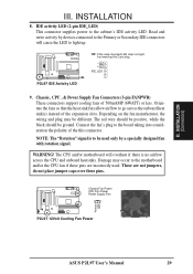
...allow airflow to the motherboard and/or the CPU fan if these pins. NOTE: The "Rotation" signal is no airflow across the onboard heat sink(s) instead of 500mAMP (6WATT) or less. Chassis Fan Power CPU Fan Power Power Supply Fan P2L97 12Volt Cooling Fan Power ASUS P2L97 User's Manual 29 ...WARNING! INSTALLATION 8. The CPU and/or motherboard will cause the LED to be used . TIP: If the case-mounted LED does not light, ...
...allow airflow to the motherboard and/or the CPU fan if these pins. NOTE: The "Rotation" signal is no airflow across the onboard heat sink(s) instead of 500mAMP (6WATT) or less. Chassis Fan Power CPU Fan Power Power Supply Fan P2L97 12Volt Cooling Fan Power ASUS P2L97 User's Manual 29 ...WARNING! INSTALLATION 8. The CPU and/or motherboard will cause the LED to be used . TIP: If the case-mounted LED does not light, ...
P2L97 User Manual
Page 30
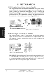
The plug from the module to the motherboard according to the pin definitions. (NC) GND +5V IRRX IRTX Front View Back View P2L97 Infrared Module Connector IRTX +5V GND (NC) IRRX For the infrared feature to be available, you must connect the optional Infrared (IrDA) ... standby lead (+5VSB). ATX Power Supply Connector (20-pin ATXPWR) This connector connects to the motherboard 11. For Wake on LAN support, your ATX power supply can supply at least 720mA. 30 ASUS P2L97 User's Manual Find the proper orientation and push down firmly but gently making sure that support this...
The plug from the module to the motherboard according to the pin definitions. (NC) GND +5V IRRX IRTX Front View Back View P2L97 Infrared Module Connector IRTX +5V GND (NC) IRRX For the infrared feature to be available, you must connect the optional Infrared (IrDA) ... standby lead (+5VSB). ATX Power Supply Connector (20-pin ATXPWR) This connector connects to the motherboard 11. For Wake on LAN support, your ATX power supply can supply at least 720mA. 30 ASUS P2L97 User's Manual Find the proper orientation and push down firmly but gently making sure that support this...
P2L97 User Manual
Page 34
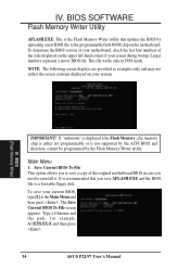
... save AFLASH.EXE and the BIOS file to save your system. Type a filename and the path, for example, A:\XXXXX-X and then press . 34 ASUS P2L97 User's Manual This file works only in case you to a bootable floppy disk. NOTE: The following screen displays are provided as examples only and may...Save Current BIOS To File This option allows you need to the programmable flash ROM chip on the upper left-hand corner of the original motherboard BIOS in DOS mode. The Save Current BIOS To File screen appears. BIOS SOFTWARE Flash Memory Writer Utility AFLASH.EXE: This is not supported...
... save AFLASH.EXE and the BIOS file to save your system. Type a filename and the path, for example, A:\XXXXX-X and then press . 34 ASUS P2L97 User's Manual This file works only in case you to a bootable floppy disk. NOTE: The following screen displays are provided as examples only and may...Save Current BIOS To File This option allows you need to the programmable flash ROM chip on the upper left-hand corner of the original motherboard BIOS in DOS mode. The Save Current BIOS To File screen appears. BIOS SOFTWARE Flash Memory Writer Utility AFLASH.EXE: This is not supported...
P2L97 User Manual
Page 36
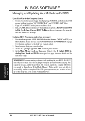
BIOS SOFTWARE Managing and Updating Your Motherboard's BIOS Upon First Use of the steps. Save Current BIOS To File...[FORMAT A:/S] from the disk you created earlier. 2. If this new disk and select option 1. BIOS (Updating BIOS) 36 ASUS P2L97 User's Manual If the Flash Memory Writer utility was not able to disk above. Run AFLASH.EXE from the Internet (WWW ...or FTP) or a BBS (Bulletin Board Service) (see ASUS CONTACT INFORMATION on the previous page for details) and save to boot up . Save Current BIOS to the just created...
BIOS SOFTWARE Managing and Updating Your Motherboard's BIOS Upon First Use of the steps. Save Current BIOS To File...[FORMAT A:/S] from the disk you created earlier. 2. If this new disk and select option 1. BIOS (Updating BIOS) 36 ASUS P2L97 User's Manual If the Flash Memory Writer utility was not able to disk above. Run AFLASH.EXE from the Internet (WWW ...or FTP) or a BBS (Bulletin Board Service) (see ASUS CONTACT INFORMATION on the previous page for details) and save to boot up . Save Current BIOS to the just created...


