
P2L97 User Manual
Page 11
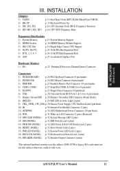
INSTALLATION Jumpers 1) CLRTC 2) KB_UP 3) FS0, FS1, FS2 4) BF0, BF1, BF2, BF3 p. 13 Real Time Clock (RTC) RAM (Short/Clear CMOS) p. 13 Keyboard Power Up p. 14 CPU External Clock (BUS) Frequency Selection p. 14 CPU"BUS Frequency Ratio Expansion Slots/Sockets 1) System Memory p. 15 ... Connector (4 pins) *The onboard hardware monitor uses the address 290H-297H so legacy ISA cards must not use this address otherwise conflicts will occur. III. ASUS P2L97 User's Manual 11 INSTALLATION (Board Layout) III.
INSTALLATION Jumpers 1) CLRTC 2) KB_UP 3) FS0, FS1, FS2 4) BF0, BF1, BF2, BF3 p. 13 Real Time Clock (RTC) RAM (Short/Clear CMOS) p. 13 Keyboard Power Up p. 14 CPU External Clock (BUS) Frequency Selection p. 14 CPU"BUS Frequency Ratio Expansion Slots/Sockets 1) System Memory p. 15 ... Connector (4 pins) *The onboard hardware monitor uses the address 290H-297H so legacy ISA cards must not use this address otherwise conflicts will occur. III. ASUS P2L97 User's Manual 11 INSTALLATION (Board Layout) III.
P2L97 User Manual
Page 13
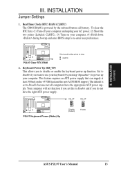
... if you set to Enable and if you do not have the appropriate ATX power supply. Real Time Clock (RTC) RAM (CLRTC) The CMOS RAM is set this to Disable because not all computers have the right ATX power supply. The default is powered by pressing ..., (4) Hold down during bootup and enter BIOS setup to clear CLRTC P2L97 Clear RTC RAM 2. R P2L97 Keyboard Power (Wake) Up KB_UP 1 2 3 Disable (Default) KB_UP 1 2 3 Enable III. Set to Enable if you to power up function. INSTALLATION (Jumpers) ASUS P2L97 User's Manual 13 R Short small solder points to re-enter user...
... if you set to Enable and if you do not have the appropriate ATX power supply. Real Time Clock (RTC) RAM (CLRTC) The CMOS RAM is set this to Disable because not all computers have the right ATX power supply. The default is powered by pressing ..., (4) Hold down during bootup and enter BIOS setup to clear CLRTC P2L97 Clear RTC RAM 2. R P2L97 Keyboard Power (Wake) Up KB_UP 1 2 3 Disable (Default) KB_UP 1 2 3 Enable III. Set to Enable if you to power up function. INSTALLATION (Jumpers) ASUS P2L97 User's Manual 13 R Short small solder points to re-enter user...
P2L97 User Manual
Page 43
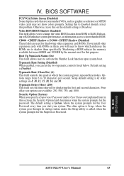
... a ROM reduces the memory available between 640KB and 1024KB by the amount used for the Supervisor Password. Options range from ROM to RAM enhances system performance, as graphic accelerators or MPEG video cards may not show colors properly. BIOS SOFTWARE PCI/VGA Palette Snoop (Disabled)... of Disabled. Relocating to RAM. Default setting is 6; Setup default setting is Disabled. Typematic Delay (Msec) (250) This field sets the time interval for this to 30 characters per second. The default setting is faster than the ROM. BIOS (BIOS Features) ASUS P2L97 User's Manual 43
... a ROM reduces the memory available between 640KB and 1024KB by the amount used for the Supervisor Password. Options range from ROM to RAM enhances system performance, as graphic accelerators or MPEG video cards may not show colors properly. BIOS SOFTWARE PCI/VGA Palette Snoop (Disabled)... of Disabled. Relocating to RAM. Default setting is 6; Setup default setting is Disabled. Typematic Delay (Msec) (250) This field sets the time interval for this to 30 characters per second. The default setting is faster than the ROM. BIOS (BIOS Features) ASUS P2L97 User's Manual 43
P2L97 User Manual
Page 53
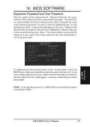
... set the system passwords. By default, the system comes without any passwords. To specify a password, highlight the type you forget the password, see CMOS RAM in the "Security Option" field of entering a new password when the "Enter Password" prompt appears. The system confirms your password and then press . ASUS P2L97 User's Manual 53
... set the system passwords. By default, the system comes without any passwords. To specify a password, highlight the type you forget the password, see CMOS RAM in the "Security Option" field of entering a new password when the "Enter Password" prompt appears. The system confirms your password and then press . ASUS P2L97 User's Manual 53


