P2L-N User Manual
Page 4
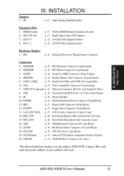
External Connectors 24 Front Panel Descriptions 29 Power Connection Procedures 33 IV. INTRODUCTION 7 How this manual is organized 7 Item Checklist 7 II. FEATURES 8 Features of the ASUS P2L-N/P2E-N Motherboard 8 Parts of Chipset Features Setup 44 4 ASUS P2L-N/P2E-N User's Manual Central Processing Unit (...41 Details of BIOS Features Setup 41 Chipset Features Setup 44 Details of the ASUS P2L-N/P2E-N Motherboard 11 Riser Card Back 11 Riser Card Front 11 III. INSTALLATION 12 ASUS P2L-N/P2E-N Motherboard Layout 12 Installation Steps 14 1. Jumpers 14 2. System Memory ...
External Connectors 24 Front Panel Descriptions 29 Power Connection Procedures 33 IV. INTRODUCTION 7 How this manual is organized 7 Item Checklist 7 II. FEATURES 8 Features of the ASUS P2L-N/P2E-N Motherboard 8 Parts of Chipset Features Setup 44 4 ASUS P2L-N/P2E-N User's Manual Central Processing Unit (...41 Details of BIOS Features Setup 41 Chipset Features Setup 44 Details of the ASUS P2L-N/P2E-N Motherboard 11 Riser Card Back 11 Riser Card Front 11 III. INSTALLATION 12 ASUS P2L-N/P2E-N Motherboard Layout 12 Installation Steps 14 1. Jumpers 14 2. System Memory ...
P2L-N User Manual
Page 5
CONTENTS Power Management Setup 47 Details of Power Management Setup 47 PNP and PCI Setup 50 Details of PNP and PCI Setup 50 Load BIOS Defaults 52 Load Setup Defaults 52 Supervisor Password and User Password 53 IDE HDD Auto Detection 54 Save & Exit Setup 55 Exit Without Saving 55 V. Other Video Drivers 83 C. Audio Driver 103 E. Audio Software 109 F. Support CD 56 Support CD Main Menu 56 A. Video Player 97 D. ASUS LAN Card (Optional 119 ASUS P2L-N/P2E-N User's Manual 5 Video Driver (Windows 95 63 B. PC Probe Utility 57 B.
CONTENTS Power Management Setup 47 Details of Power Management Setup 47 PNP and PCI Setup 50 Details of PNP and PCI Setup 50 Load BIOS Defaults 52 Load Setup Defaults 52 Supervisor Password and User Password 53 IDE HDD Auto Detection 54 Save & Exit Setup 55 Exit Without Saving 55 V. Other Video Drivers 83 C. Audio Driver 103 E. Audio Software 109 F. Support CD 56 Support CD Main Menu 56 A. Video Player 97 D. ASUS LAN Card (Optional 119 ASUS P2L-N/P2E-N User's Manual 5 Video Driver (Windows 95 63 B. PC Probe Utility 57 B.
P2L-N User Manual
Page 7
... up the BIOS software Information on -LAN 10/100 Ethernet Card (optional) ASUS P2L-N/P2E-N User's Manual 7 BIOS Software: V. Features: III. If you discover damaged or missing items, please contact your retailer. (1) ASUS motherboard (1) Retention mechanism & heatsink support (2) Attach mount bridges (preinstalled) (1)...Manual (1) System housing User's Manual (1) NLX Form-factor system housing, riser card, and power supply DIMM memory module 3.5inch Floppy Drive Slim CD-ROM and cable ASUS PCI-L101 Wake-on the included support software Item Checklist Please check that your package is ...
... up the BIOS software Information on -LAN 10/100 Ethernet Card (optional) ASUS P2L-N/P2E-N User's Manual 7 BIOS Software: V. Features: III. If you discover damaged or missing items, please contact your retailer. (1) ASUS motherboard (1) Retention mechanism & heatsink support (2) Attach mount bridges (preinstalled) (1)...Manual (1) System housing User's Manual (1) NLX Form-factor system housing, riser card, and power supply DIMM memory module 3.5inch Floppy Drive Slim CD-ROM and cable ASUS PCI-L101 Wake-on the included support software Item Checklist Please check that your package is ...
P2L-N User Manual
Page 8
...parallel port with an onboard PCI Bus Master IDE control- ler with two connectors that supports four IDE devices in a small package. ASUS P2L-N/P2E-N Specifications: • NLX: Features ASUS' custom designed NLX form factor. • Multi-Speed: Supports the Intel Pentium® II (233MHz-333MHz) and Celeron™ ... VGA: Has ATI 3D Rage Pro AGP 2X VGA chipset onboard with several memory options from COM2 to 256MB. • Riser Card: Provides NLX power, primary IDE, floppy drive, LAN wake up . • Onboard IrDA: Has an infrared port on the riser card for wireless interface. •...
...parallel port with an onboard PCI Bus Master IDE control- ler with two connectors that supports four IDE devices in a small package. ASUS P2L-N/P2E-N Specifications: • NLX: Features ASUS' custom designed NLX form factor. • Multi-Speed: Supports the Intel Pentium® II (233MHz-333MHz) and Celeron™ ... VGA: Has ATI 3D Rage Pro AGP 2X VGA chipset onboard with several memory options from COM2 to 256MB. • Riser Card: Provides NLX power, primary IDE, floppy drive, LAN wake up . • Onboard IrDA: Has an infrared port on the riser card for wireless interface. •...
P2L-N User Manual
Page 9
... be used. • Desktop Management Interface (DMI): Supports DMI through optional ASUS PCI-L101 Fast Ethernet card. FEATURES ASUS P2L-N/P2E-N Special Features: • ACPI Ready: ACPI (Advanced Configuration and Power Interface) is no need to upgrade current hard drives or cables. •... SDRAM Optimized Performance: ASUS smart series of motherboards support the new generation memory,...
... be used. • Desktop Management Interface (DMI): Supports DMI through optional ASUS PCI-L101 Fast Ethernet card. FEATURES ASUS P2L-N/P2E-N Special Features: • ACPI Ready: ACPI (Advanced Configuration and Power Interface) is no need to upgrade current hard drives or cables. •... SDRAM Optimized Performance: ASUS smart series of motherboards support the new generation memory,...
P2L-N User Manual
Page 10
...more critical for its normal RPM range and alarm thresholds. • Keyboard Power Up: Keyboard Power Up can be enabled or disabled to allow the computer to ensure proper system configuration and management. 10 ASUS P2L-N/P2E-N User's Manual Each fan can be set for future processors, so... monitoring is the Soft-Off mode. FEATURES Features II. With this benefit on remotely through an external modem. When the power button is in one of damaging ...
...more critical for its normal RPM range and alarm thresholds. • Keyboard Power Up: Keyboard Power Up can be enabled or disabled to allow the computer to ensure proper system configuration and management. 10 ASUS P2L-N/P2E-N User's Manual Each fan can be set for future processors, so... monitoring is the Soft-Off mode. FEATURES Features II. With this benefit on remotely through an external modem. When the power button is in one of damaging ...
P2L-N User Manual
Page 11
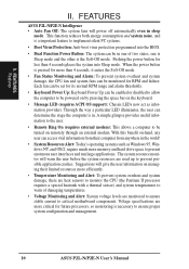
FEATURES Parts of the ASUS P2L-N/P2E-N Motherboard T: Parallel Conn. COM 2 Conn.(optional) Conn.(optional) Connector Joystick/MIDI Connector II. FEATURES Motherboard Parts T: PS/2 Mouse B: PS/2 Keyboard Intel 440LX or 440EX AGPset Onboard ESS Audio 2 DIMM Sockets SEC CPU Socket (for Pentium II) Intel PIIX4 PCIset ASUS ASIC Keyboard BIOS, ...PCI Slots 1 ISA Slot NLX Slot Riser Card Back IrDA Port 2 USB Ports Riser Card Front Floppy Drive Connector Primary IDE Connector NLX Power Connector ASUS P2L-N/P2E-N User's Manual 11 TV Out S-Video TV Out RCA VGA COM 1 B: Serial Conn. II.
FEATURES Parts of the ASUS P2L-N/P2E-N Motherboard T: Parallel Conn. COM 2 Conn.(optional) Conn.(optional) Connector Joystick/MIDI Connector II. FEATURES Motherboard Parts T: PS/2 Mouse B: PS/2 Keyboard Intel 440LX or 440EX AGPset Onboard ESS Audio 2 DIMM Sockets SEC CPU Socket (for Pentium II) Intel PIIX4 PCIset ASUS ASIC Keyboard BIOS, ...PCI Slots 1 ISA Slot NLX Slot Riser Card Back IrDA Port 2 USB Ports Riser Card Front Floppy Drive Connector Primary IDE Connector NLX Power Connector ASUS P2L-N/P2E-N User's Manual 11 TV Out S-Video TV Out RCA VGA COM 1 B: Serial Conn. II.
P2L-N User Manual
Page 12
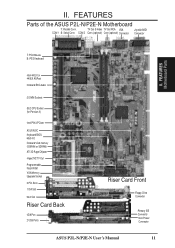
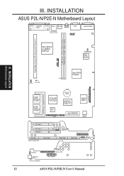
...Front Riser Slot Riser Slot Floppy Drive Conn. Panel Conn. Riser Slot MIC Con. Infrared USB1&2 Riser Card Back Primary IDE NLX Power ASUS P2L-N/P2E-N User's Manual INSTALLATION Motherboard Layout 12 CPU_FAN RT4 CPU Thermal Sensor Lead Row 0 1 2 3 Intel PIIX4 Chipset CDROM Connector... 2X VGA Chipset Impac TV2 1 AMC CMOS Power CR2032 3 Volt Cell Keyboard BIOS, RTC, & Multi-I/O ASUS ASIC Flash EEPROM (Programmable BIOS) Hardware Monitor PCI Slot 2 PCI Slot 1 ISA Slot 1 LAN LED Wake on LAN NLX Ext. INSTALLATION ASUS P2L-N/P2E-N Motherboard Layout COM 1 Parallel COM ...
...Front Riser Slot Riser Slot Floppy Drive Conn. Panel Conn. Riser Slot MIC Con. Infrared USB1&2 Riser Card Back Primary IDE NLX Power ASUS P2L-N/P2E-N User's Manual INSTALLATION Motherboard Layout 12 CPU_FAN RT4 CPU Thermal Sensor Lead Row 0 1 2 3 Intel PIIX4 Chipset CDROM Connector... 2X VGA Chipset Impac TV2 1 AMC CMOS Power CR2032 3 Volt Cell Keyboard BIOS, RTC, & Multi-I/O ASUS ASIC Flash EEPROM (Programmable BIOS) Hardware Monitor PCI Slot 2 PCI Slot 1 ISA Slot 1 LAN LED Wake on LAN NLX Ext. INSTALLATION ASUS P2L-N/P2E-N Motherboard Layout COM 1 Parallel COM ...
P2L-N User Manual
Page 13
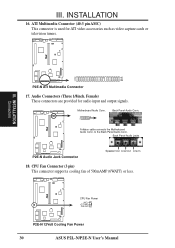
... 9) IR p. 26 Infrared Module 10) POWER p. 26 NLX Motherboard Power Connector (20-pin Block) 11) IDE1 p. 27 Primary IDE Connector (40-pin Block) 12) FLOPPY p. 27 Floppy Drive Connector (34-pin Block) 13. INSTALLATION Map of Board Jumpers 1) JP1 III. III. ASUS P2L-N/P2E-N User's Manual 13 LAN_LED, WOL_ ... 30 ATI Multimedia Connector (40-3 pin Block) 17) AUDIO p. 30 Back Panel Audio Connectors (10-1 pin Block) 18) CPU_FAN p. 30 CPU Fan Power (3-pin Block) 19) VGA Memory p. 31 Onboard VGA Memory Expansion Sockets (40 pins) 20) CDROM p. 31 CD-ROM Drive Connector (50-1 pins...
... 9) IR p. 26 Infrared Module 10) POWER p. 26 NLX Motherboard Power Connector (20-pin Block) 11) IDE1 p. 27 Primary IDE Connector (40-pin Block) 12) FLOPPY p. 27 Floppy Drive Connector (34-pin Block) 13. INSTALLATION Map of Board Jumpers 1) JP1 III. III. ASUS P2L-N/P2E-N User's Manual 13 LAN_LED, WOL_ ... 30 ATI Multimedia Connector (40-3 pin Block) 17) AUDIO p. 30 Back Panel Audio Connectors (10-1 pin Block) 18) CPU_FAN p. 30 CPU Fan Power (3-pin Block) 19) VGA Memory p. 31 Onboard VGA Memory Expansion Sockets (40 pins) 20) CDROM p. 31 CD-ROM Drive Connector (50-1 pins...
P2L-N User Manual
Page 14
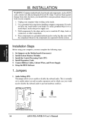
Computer motherboards, baseboards and components, such as the power supply case. 3. Hold components by the edges and try not to a metal object, such as SCSI cards, contain very delicate Integrated Circuit (IC)...antistatic pad or on the Motherboard (if necessary) 2. JP1 3 2 1 Audio Enable JP1 3 2 1 Audio Disable R P2E-N Onboard Audio Setting 14 ASUS P2L-N/P2E-N User's Manual Connect Ribbon Cables, Cabinet Wires, and Power Supply 6. Unplug your computer. 1. III. INSTALLATION Jumpers III. To protect them against damage from the system. Set Jumpers on the bag...
Computer motherboards, baseboards and components, such as the power supply case. 3. Hold components by the edges and try not to a metal object, such as SCSI cards, contain very delicate Integrated Circuit (IC)...antistatic pad or on the Motherboard (if necessary) 2. JP1 3 2 1 Audio Enable JP1 3 2 1 Audio Disable R P2E-N Onboard Audio Setting 14 ASUS P2L-N/P2E-N User's Manual Connect Ribbon Cables, Cabinet Wires, and Power Supply 6. Unplug your computer. 1. III. INSTALLATION Jumpers III. To protect them against damage from the system. Set Jumpers on the bag...
P2L-N User Manual
Page 15
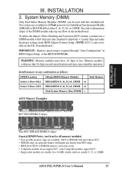
...128MB. To utilize the chipset's Error Checking and Correction (ECC) feature, you must have 18 chips or less. ASUS P2L-N/P2E-N User's Manual 15 INSTALLATION 2. System Memory (DIMM) Only Dual Inline Memory Modules (DIMM) can be used ...128MB x1 Socket 2 (Rows 2&3) SDRAM/EDO 8, 16, 32, 64, 128MB x1 Total System Memory (Max 256MB) = ASUS Memory Examples: ECC EDO DIMM (9 chips) III. Install memory in the BIOS Chipset Features Setup. (NOTE: ECC is ...8226; SDRAM chips are available for 3.3Volt (power level) Unbuffered Synchronous DRAMs (SDRAM) or EDO DRAM of the BIOS SOFTWARE. III.
...128MB. To utilize the chipset's Error Checking and Correction (ECC) feature, you must have 18 chips or less. ASUS P2L-N/P2E-N User's Manual 15 INSTALLATION 2. System Memory (DIMM) Only Dual Inline Memory Modules (DIMM) can be used ...128MB x1 Socket 2 (Rows 2&3) SDRAM/EDO 8, 16, 32, 64, 128MB x1 Total System Memory (Max 256MB) = ASUS Memory Examples: ECC EDO DIMM (9 chips) III. Install memory in the BIOS Chipset Features Setup. (NOTE: ECC is ...8226; SDRAM chips are available for 3.3Volt (power level) Unbuffered Synchronous DRAMs (SDRAM) or EDO DRAM of the BIOS SOFTWARE. III.
P2L-N User Manual
Page 22
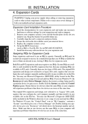
...IRQs are available to both your expansion card, such as IRQ xx Used By ISA: Yes in any necessary hardware or software settings for your power supply when adding or removing expansion cards or other system components. The original ISA expansion card design, now referred to as legacy ISA cards,... no two devices share the same IRQs or your computer will experience problems when those two devices are in use at the same time. 22 ASUS P2L-N/P2E-N User's Manual Currently, there are already in use , leaving 6 IRQs free for Expansion Cards Some expansion cards need to use an IRQ to...
...IRQs are available to both your expansion card, such as IRQ xx Used By ISA: Yes in any necessary hardware or software settings for your power supply when adding or removing expansion cards or other system components. The original ISA expansion card design, now referred to as legacy ISA cards,... no two devices share the same IRQs or your computer will experience problems when those two devices are in use at the same time. 22 ASUS P2L-N/P2E-N User's Manual Currently, there are already in use , leaving 6 IRQs free for Expansion Cards Some expansion cards need to use an IRQ to...
P2L-N User Manual
Page 24
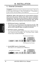
...INSTALLATION Connectors III. External Connectors WARNING! PS/2 Mouse (6-pin Female) PS/2 Keyboard (6-pin Female) 3. Joystick/Midi (15-pin Female) 24 ASUS P2L-N/P2E-N User's Manual Placing jumper caps over these will cause damage to the PS/2 mouse if one is the side closest to mini DIN ...) This connector is for a standard joystick or MIDI device. Joystick/MIDI Connector (15 pin Female) This connector is for connectors or power sources. III. These are labeled on hard drives and floppy drives. The four corners of the BIOS SOFTWARE. This connector will direct IRQ12...
...INSTALLATION Connectors III. External Connectors WARNING! PS/2 Mouse (6-pin Female) PS/2 Keyboard (6-pin Female) 3. Joystick/Midi (15-pin Female) 24 ASUS P2L-N/P2E-N User's Manual Placing jumper caps over these will cause damage to the PS/2 mouse if one is the side closest to mini DIN ...) This connector is for a standard joystick or MIDI device. Joystick/MIDI Connector (15 pin Female) This connector is for connectors or power sources. III. These are labeled on hard drives and floppy drives. The four corners of the BIOS SOFTWARE. This connector will direct IRQ12...
P2L-N User Manual
Page 26
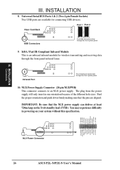
...Volts +3.3 Volts +12.0 Volts +5V Standby Power OK Ground 5.0 Volts Ground +5.0 Volts Ground +3.3 Volts +3.3 Volts NLX Power Connector 26 ASUS P2L-N/P2E-N User's Manual NLX Power Supply Connector (20 pin NLXPWR) This connector connects to an NLX power supply. Find the proper orientation and push down... firmly making sure that the NLX power supply can deliver at least ...
...Volts +3.3 Volts +12.0 Volts +5V Standby Power OK Ground 5.0 Volts Ground +5.0 Volts Ground +3.3 Volts +3.3 Volts NLX Power Connector 26 ASUS P2L-N/P2E-N User's Manual NLX Power Supply Connector (20 pin NLXPWR) This connector connects to an NLX power supply. Find the proper orientation and push down... firmly making sure that the NLX power supply can deliver at least ...
P2L-N User Manual
Page 27
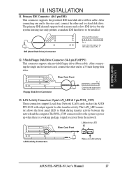
...Orient the red stripe on the floppy ribbon cable to power up when there is a wakeup package (signal) received from the network. LAN Activity Connectors (2 pin LAN_LED & 3 pin WOL_CON) These connectors support Local Area Network (LAN) cards such as the ASUS PCI-L101 with output signals for data transfer activity....the system to Pin 1 13. III. IDE (Hard Disk Drive) Connector Primary IDE Connector Pin 1 Orient the red stripe on LAN activity ASUS P2L-N/P2E-N User's Manual 27 LAN activity LED Riser Card Front LAN Activity Connectors Riser Slot Wake on the IDE ribbon cable to a hard disk...
...Orient the red stripe on the floppy ribbon cable to power up when there is a wakeup package (signal) received from the network. LAN Activity Connectors (2 pin LAN_LED & 3 pin WOL_CON) These connectors support Local Area Network (LAN) cards such as the ASUS PCI-L101 with output signals for data transfer activity....the system to Pin 1 13. III. IDE (Hard Disk Drive) Connector Primary IDE Connector Pin 1 Orient the red stripe on LAN activity ASUS P2L-N/P2E-N User's Manual 27 LAN activity LED Riser Card Front LAN Activity Connectors Riser Slot Wake on the IDE ribbon cable to a hard disk...

P2L-N User Manual
Page 29
...mode. Infrared Window Allows transmission and reception of the BIOS SOFTWARE. ASUS P2L-N/P2E-N User's Manual 29 C. Network Activity LED Blinks when data is data being transfered or waiting in the POWER MANAGEMENT SETUP of infrared signals by the onboard module. Reset Button ... audio source. G. Microphone Jack Accepts a 1/8inch connector from a network card. (The network card requires an external LED wire connected to use the power switch H. III. F. INSTALLATION Connectors A B C DEF G H I . Message LED The LED will remain lit when there is no modem activity...
...mode. Infrared Window Allows transmission and reception of the BIOS SOFTWARE. ASUS P2L-N/P2E-N User's Manual 29 C. Network Activity LED Blinks when data is data being transfered or waiting in the POWER MANAGEMENT SETUP of infrared signals by the onboard module. Reset Button ... audio source. G. Microphone Jack Accepts a 1/8inch connector from a network card. (The network card requires an external LED wire connected to use the power switch H. III. F. INSTALLATION Connectors A B C DEF G H I . Message LED The LED will remain lit when there is no modem activity...
P2L-N User Manual
Page 30
... or television tuners. III. Back Panel Audio Jacks P2E-N Audio Jack Connector Speaker Out Line Out Line In 18. R CPU Fan Power (NC) +12 Volt Ground P2E-N 12Volt Cooling Fan Power 30 ASUS P2L-N/P2E-N User's Manual ATI Multimedia Connector (40-3 pin AMC) This connector is used for audio input and output signals. to...
... or television tuners. III. Back Panel Audio Jacks P2E-N Audio Jack Connector Speaker Out Line Out Line In 18. R CPU Fan Power (NC) +12 Volt Ground P2E-N 12Volt Cooling Fan Power 30 ASUS P2L-N/P2E-N User's Manual ATI Multimedia Connector (40-3 pin AMC) This connector is used for audio input and output signals. to...
P2L-N User Manual
Page 33
... down . NOTE: The message "You can press the ATX power switch after Windows shuts down your devices in the following order: a. Be sure that is pressed. Follow the instructions in some systems, marked with ATX power supplies. ASUS P2L-N/P2E-N User's Manual 33 You may then turn on the ...screen. For ATX power supplies, you can now safely turn off (in the next section, BIOS SOFTWARE. * Powering Off your computer: You must first exit or shut ...
... down . NOTE: The message "You can press the ATX power switch after Windows shuts down your devices in the following order: a. Be sure that is pressed. Follow the instructions in some systems, marked with ATX power supplies. ASUS P2L-N/P2E-N User's Manual 33 You may then turn on the ...screen. For ATX power supplies, you can now safely turn off (in the next section, BIOS SOFTWARE. * Powering Off your computer: You must first exit or shut ...
P2L-N User Manual
Page 37
... the BIOS version at the time of the configuration settings for specifying the system configuration and settings. Your BIOS version may have already been made. ASUS P2L-N/P2E-N User's Manual 37 If your motherboard came in particular, the hard disk specifications. in a computer system, the proper configuration entries may be updated when... Flash Memory Writer utility to call up Setup. If so, invoke the Setup utility, as described in detail in this program. This appears during the Power-On Self Test (POST). BIOS BIOS Setup NOTE: The following options: IV.
... the BIOS version at the time of the configuration settings for specifying the system configuration and settings. Your BIOS version may have already been made. ASUS P2L-N/P2E-N User's Manual 37 If your motherboard came in particular, the hard disk specifications. in a computer system, the proper configuration entries may be updated when... Flash Memory Writer utility to call up Setup. If so, invoke the Setup utility, as described in detail in this program. This appears during the Power-On Self Test (POST). BIOS BIOS Setup NOTE: The following options: IV.
P2L-N User Manual
Page 38
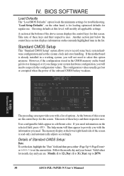
"Load Setup Defaults", on the board gets lost or corrupted when the power of this screen are : Month: (1 to 12), Day: (1 to 31), Year: (up to set the system clock and error handling. The configuration values usually get ... display at the bottom of Standard CMOS Setup: Date To set the date, highlight the "Date" field and then press either / or / to 2079) 38 ASUS P2L-N/P2E-N User's Manual Valid values for troubleshooting. BIOS SOFTWARE Load Defaults The "Load BIOS Defaults" option loads the minimum settings for month, day and year...
"Load Setup Defaults", on the board gets lost or corrupted when the power of this screen are : Month: (1 to 12), Day: (1 to 31), Year: (up to set the system clock and error handling. The configuration values usually get ... display at the bottom of Standard CMOS Setup: Date To set the date, highlight the "Date" field and then press either / or / to 2079) 38 ASUS P2L-N/P2E-N User's Manual Valid values for troubleshooting. BIOS SOFTWARE Load Defaults The "Load BIOS Defaults" option loads the minimum settings for month, day and year...


