
P2B98-XV User Manual
Page 2
... OR INACCURACIES THAT MAY APPEAR IN THIS MANUAL, INCLUDING THE PRODUCTS AND SOFTWARE DESCRIBED IN IT. Product Name: ASUS P2B98-XV Manual Revision: 2.00 Release Date: August 1998 2 ASUS P2B98-XV User's Manual The product name and revision number are represented by the third digit in any form or by any..., transcribed, stored in a retrieval system, or translated into any language in the manual revision number. For previous or updated manuals, BIOS, drivers, or product release information, contact ASUS at http://www.asus.com.tw or through any of Adobe Systems Incorporated.
... OR INACCURACIES THAT MAY APPEAR IN THIS MANUAL, INCLUDING THE PRODUCTS AND SOFTWARE DESCRIBED IN IT. Product Name: ASUS P2B98-XV Manual Revision: 2.00 Release Date: August 1998 2 ASUS P2B98-XV User's Manual The product name and revision number are represented by the third digit in any form or by any..., transcribed, stored in a retrieval system, or translated into any language in the manual revision number. For previous or updated manuals, BIOS, drivers, or product release information, contact ASUS at http://www.asus.com.tw or through any of Adobe Systems Incorporated.
P2B98-XV User Manual
Page 4
... Details of Chipset Features Setup 42 Power Management Setup 45 Details of the ASUS P2B98-XV Motherboard 8 The ASUS P2B98-XV Motherboard 9 III. CONTENTS I. INSTALLATION 10 Layout of the ASUS P2B98-XV Motherboard 10 Installation Steps 12 1. System Memory (DIMM 16 DIMM Memory Installation Procedures 17 3. BIOS SOFTWARE 32 Flash Memory Writer Utility 32 Main Menu 32 Managing and Updating...
... Details of Chipset Features Setup 42 Power Management Setup 45 Details of the ASUS P2B98-XV Motherboard 8 The ASUS P2B98-XV Motherboard 9 III. CONTENTS I. INSTALLATION 10 Layout of the ASUS P2B98-XV Motherboard 10 Installation Steps 12 1. System Memory (DIMM 16 DIMM Memory Installation Procedures 17 3. BIOS SOFTWARE 32 Flash Memory Writer Utility 32 Main Menu 32 Managing and Updating...
P2B98-XV User Manual
Page 5
Support CD 55 Support CD Main Menu 57 A. Video Driver 58 B. Video Player 79 D. ASUS LAN Card 85 ASUS P2B98-XV User's Manual 5 CONTENTS PNP and PCI Setup 48 Details of PNP and PCI Setup 48 Load BIOS Defaults 50 Load Setup Defaults 50 Supervisor Password and User Password 51 IDE HDD Auto Detection 52 Save & Exit Setup 53 Exit Without Saving 53 V. DMI Configuration Utility 81 VI. Other Video Drivers 65 C.
Support CD 55 Support CD Main Menu 57 A. Video Driver 58 B. Video Player 79 D. ASUS LAN Card 85 ASUS P2B98-XV User's Manual 5 CONTENTS PNP and PCI Setup 48 Details of PNP and PCI Setup 48 Load BIOS Defaults 50 Load Setup Defaults 50 Supervisor Password and User Password 51 IDE HDD Auto Detection 52 Save & Exit Setup 53 Exit Without Saving 53 V. DMI Configuration Utility 81 VI. Other Video Drivers 65 C.
P2B98-XV User Manual
Page 7
... spare jumpers (1) Support drivers and utilities: (1) User's Manual ASUS PCI-L101 Wake-on the included support software VI. BIOS Software: Instructions on setting up the BIOS software V. INTRODUCTION How this product III. INTRODUCTION Manual / Checklist I . Support CD: Information on -LAN 10/100 Ethernet Card (optional) ASUS P2B98-XV User's Manual 7 If you discover damaged or missing...
... spare jumpers (1) Support drivers and utilities: (1) User's Manual ASUS PCI-L101 Wake-on the included support software VI. BIOS Software: Instructions on setting up the BIOS software V. INTRODUCTION How this product III. INTRODUCTION Manual / Checklist I . Support CD: Information on -LAN 10/100 Ethernet Card (optional) ASUS P2B98-XV User's Manual 7 If you discover damaged or missing...
P2B98-XV User Manual
Page 8
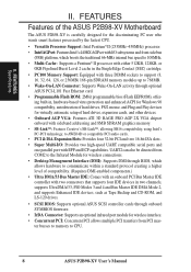
...front-side bus (FSB) platform, which allows hardware to CPU. 8 ASUS P2B98-XV User's Manual UART2 can also be directed from PCI mas- II. FEATURES Features of the ASUS P2B98-XV Motherboard The ASUS P2B98-XV is carefully designed for wireless interface. • Concurrent PCI: Concurrent PCI... allows multiple PCI transfers from COM2 to the Infrared Module for wireless connections. • Desktop Management Interface (DMI): Supports DMI through BIOS, which ...
...front-side bus (FSB) platform, which allows hardware to CPU. 8 ASUS P2B98-XV User's Manual UART2 can also be directed from PCI mas- II. FEATURES Features of the ASUS P2B98-XV Motherboard The ASUS P2B98-XV is carefully designed for wireless interface. • Concurrent PCI: Concurrent PCI... allows multiple PCI transfers from COM2 to the Infrared Module for wireless connections. • Desktop Management Interface (DMI): Supports DMI through BIOS, which ...
P2B98-XV User Manual
Page 10
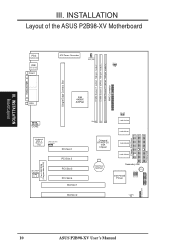
INSTALLATION Layout of the ASUS P2B98-XV Motherboard PARALLEL PORT Single Edge Contact Slot DIMM Socket 1 (64-bit, 168-pin module) DIMM Socket 2 ...USB 2 (BOTTOM) COM 1 ATX Power Connector SYS_FAN CPU_FAN BUS Freq. FSB Intel 440BX VGA AGPset COM2 Keyboard BIOS & Multi-I/O Chip Wake-On-LAN Connector PCI Slot 1 PCI Slot 2 Flash EEPROM (Programable BIOS) SB-LINK™ Connector PCI Slot 3 PCI Slot 4 ISA Slot 1 ISA Slot 2 Row 0 1 2... Floppy Disk Drive Primary IDE BF0 BF1 BF2 BF3 Infrared (IrDA) Panel Connectors 10 ASUS P2B98-XV User's Manual INSTALLATION Board Layout III.
INSTALLATION Layout of the ASUS P2B98-XV Motherboard PARALLEL PORT Single Edge Contact Slot DIMM Socket 1 (64-bit, 168-pin module) DIMM Socket 2 ...USB 2 (BOTTOM) COM 1 ATX Power Connector SYS_FAN CPU_FAN BUS Freq. FSB Intel 440BX VGA AGPset COM2 Keyboard BIOS & Multi-I/O Chip Wake-On-LAN Connector PCI Slot 1 PCI Slot 2 Flash EEPROM (Programable BIOS) SB-LINK™ Connector PCI Slot 3 PCI Slot 4 ISA Slot 1 ISA Slot 2 Row 0 1 2... Floppy Disk Drive Primary IDE BF0 BF1 BF2 BF3 Infrared (IrDA) Panel Connectors 10 ASUS P2B98-XV User's Manual INSTALLATION Board Layout III.
P2B98-XV User Manual
Page 12
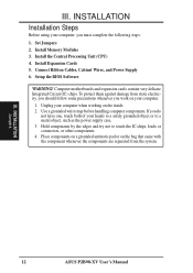
Install Memory Modules 3. Setup the BIOS Software WARNING! To protect them against damage from the system. Hold components by the edges and try not to a metal object, such as the power ... precautions whenever you must complete the following steps: 1. Set Jumpers 2. Computer motherboards and expansion cards contain very delicate Integrated Circuit (IC) chips. INSTALLATION Jumpers 12 ASUS P2B98-XV User's Manual
Install Memory Modules 3. Setup the BIOS Software WARNING! To protect them against damage from the system. Hold components by the edges and try not to a metal object, such as the power ... precautions whenever you must complete the following steps: 1. Set Jumpers 2. Computer motherboards and expansion cards contain very delicate Integrated Circuit (IC) chips. INSTALLATION Jumpers 12 ASUS P2B98-XV User's Manual

P2B98-XV User Manual
Page 13
..., (2) Short the two solder points labeled CLRTC, (3) Turn on your computer, (4) Hold down during bootup and enter BIOS setup to clear CMOS P2B98-XV Real Time Clock RAM (CLRTC) 2. The default disables the chipset's internal interrupt routing. INSTALLATION 1. Some video capture cards... that the interrupt be assigned by the onboard button cell battery. P2B98-XV VGA Interrupt INT 1 2 3 Enabled INT 1 2 3 Disabled III. Jumpers 1. Short the solder points to re-enter user preferences. INSTALLATION Jumpers ASUS P2B98-XV User's Manual 13 Clear Real Time Clock (RTC) RAM (CLRTC...
..., (2) Short the two solder points labeled CLRTC, (3) Turn on your computer, (4) Hold down during bootup and enter BIOS setup to clear CMOS P2B98-XV Real Time Clock RAM (CLRTC) 2. The default disables the chipset's internal interrupt routing. INSTALLATION 1. Some video capture cards... that the interrupt be assigned by the onboard button cell battery. P2B98-XV VGA Interrupt INT 1 2 3 Enabled INT 1 2 3 Disabled III. Jumpers 1. Short the solder points to re-enter user preferences. INSTALLATION Jumpers ASUS P2B98-XV User's Manual 13 Clear Real Time Clock (RTC) RAM (CLRTC...

P2B98-XV User Manual
Page 16
...Memory modules with 9 chips per side (standard 8 chips/side + 1 parity chip) and make the proper settings in 32, 64, 128, 256MB. 16 ASUS P2B98-XV User's Manual IMPORTANT (see General DIMM Notes below) • SDRAMs used because of the DIMM module takes up one row on bootup screen. • 8... chips/side modules do not support ECC, only 9 chips/side modules support ECC. • Single-sided DIMMs come in the BIOS Chipset Features Setup. double-sided come in any combination as follows: DIMM Location 168-pin DIMM Memory Modules Total Memory Socket 1 (Rows 0&1) SDRAM ...
...Memory modules with 9 chips per side (standard 8 chips/side + 1 parity chip) and make the proper settings in 32, 64, 128, 256MB. 16 ASUS P2B98-XV User's Manual IMPORTANT (see General DIMM Notes below) • SDRAMs used because of the DIMM module takes up one row on bootup screen. • 8... chips/side modules do not support ECC, only 9 chips/side modules support ECC. • Single-sided DIMMs come in the BIOS Chipset Features Setup. double-sided come in any combination as follows: DIMM Location 168-pin DIMM Memory Modules Total Memory Socket 1 (Rows 0&1) SDRAM ...

P2B98-XV User Manual
Page 23
... used and free IRQs. Secure the card on the slot you configure the card's jumpers manually and then install it in use . 3. Set up the BIOS if necessary (such as legacy ISA cards, requires that no two devices share the same IRQs or your expansion card, such as jumpers. 2. In a standard... or removing expansion cards or other system components. Expansion Card Installation Procedure 1. Currently, there are already in any remaining IRQs are available to operate. III. ASUS P2B98-XV User's Manual 23
... used and free IRQs. Secure the card on the slot you configure the card's jumpers manually and then install it in use . 3. Set up the BIOS if necessary (such as legacy ISA cards, requires that no two devices share the same IRQs or your expansion card, such as jumpers. 2. In a standard... or removing expansion cards or other system components. Expansion Card Installation Procedure 1. Currently, there are already in any remaining IRQs are available to operate. III. ASUS P2B98-XV User's Manual 23
P2B98-XV User Manual
Page 24
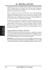
...card is automatically assigned to PCI expansion cards after those IRQs and DMAs you need to INT A. INSTALLATION Expansion Cards 24 ASUS P2B98-XV User's Manual The PCI and PNP configuration of the BIOS Setup utility. For older Legacy cards that the jumpers on this motherboard use a DMA (Direct Memory Access) channel. ...INT (interrupt) assignment. An IRQ number is added to a PCI slot that has a card in the PCI and PnP configuration section of the BIOS setup utility can be sure that do not work with the Plug and Play (PNP) specification which IRQs are handled the same way as the...
...card is automatically assigned to PCI expansion cards after those IRQs and DMAs you need to INT A. INSTALLATION Expansion Cards 24 ASUS P2B98-XV User's Manual The PCI and PNP configuration of the BIOS Setup utility. For older Legacy cards that the jumpers on this motherboard use a DMA (Direct Memory Access) channel. ...INT (interrupt) assignment. An IRQ number is added to a PCI slot that has a card in the PCI and PnP configuration section of the BIOS setup utility can be sure that do not work with the Plug and Play (PNP) specification which IRQs are handled the same way as the...
P2B98-XV User Manual
Page 25
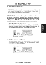
...power connector on the motherboard. PS/2 Mouse (6-pin Female) ASUS P2B98-XV User's Manual 25 External Connectors WARNING! PS/2 Mouse Connector (6-pin Female) The system will direct IRQ12 to mini DIN adapter on the Pin 1 side of the BIOS SOFTWARE. INSTALLATION Connectors III. You may use IRQ12. If...(46cm), with the red stripe on standard AT keyboards. IMPORTANT: Ribbon cables should always be less than 6in. (15cm) from jumpers in BIOS Features Setup of the connector. The four corners of the Motherboard." III. See "PS/2 Mouse Control" in "Map of the connectors are...
...power connector on the motherboard. PS/2 Mouse (6-pin Female) ASUS P2B98-XV User's Manual 25 External Connectors WARNING! PS/2 Mouse Connector (6-pin Female) The system will direct IRQ12 to mini DIN adapter on the Pin 1 side of the BIOS SOFTWARE. INSTALLATION Connectors III. You may use IRQ12. If...(46cm), with the red stripe on standard AT keyboards. IMPORTANT: Ribbon cables should always be less than 6in. (15cm) from jumpers in BIOS Features Setup of the connector. The four corners of the Motherboard." III. See "PS/2 Mouse Control" in "Map of the connectors are...
P2B98-XV User Manual
Page 26
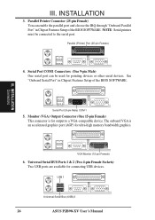
...Parallel Port" in Chipset Features Setup of the BIOS SOFTWARE. Universal Serial BUS Ports 1 & 2 (Two 4-pin Female Sockets) Two USB ports are available for ultra-high memory bandwidth graphics. USB 1 Universal Serial Bus (USB) 2 26 ASUS P2B98-XV User's Manual See "Onboard Serial Port" in ...Chipset Features Setup of the BIOS SOFTWARE. Monitor (VGA) Output Connector (One 15-pin Female) This connector is an accelerated graphics port...
...Parallel Port" in Chipset Features Setup of the BIOS SOFTWARE. Universal Serial BUS Ports 1 & 2 (Two 4-pin Female Sockets) Two USB ports are available for ultra-high memory bandwidth graphics. USB 1 Universal Serial Bus (USB) 2 26 ASUS P2B98-XV User's Manual See "Onboard Serial Port" in ...Chipset Features Setup of the BIOS SOFTWARE. Monitor (VGA) Output Connector (One 15-pin Female) This connector is an accelerated graphics port...
P2B98-XV User Manual
Page 30
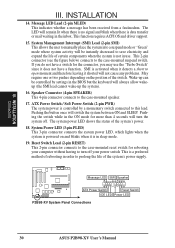
... by settings in order to turn the system off. Message LED SMI Speaker Ground ATX Power Switch Reset Switch IDE LED Power LED P2B98-XV System Panel Connections 30 ASUS P2B98-XV User's Manual Message LED Lead (2-pin MLED) This indicates whether a message has been received from a fax/modem. SMI is data transfer ...therefore leaving it does not have a switch for the connector, you may use . The system power LED shows the status of rebooting in the BIOS but the keyboard will not cause any problems. May require one or two pushes depending on and blinks when it is in the ON mode...
... by settings in order to turn the system off. Message LED SMI Speaker Ground ATX Power Switch Reset Switch IDE LED Power LED P2B98-XV System Panel Connections 30 ASUS P2B98-XV User's Manual Message LED Lead (2-pin MLED) This indicates whether a message has been received from a fax/modem. SMI is data transfer ...therefore leaving it does not have a switch for the connector, you may use . The system power LED shows the status of rebooting in the BIOS but the keyboard will not cause any problems. May require one or two pushes depending on and blinks when it is in the ON mode...
P2B98-XV User Manual
Page 31
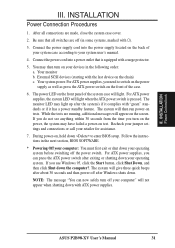
...has a power standby feature. Recheck your jumper settings and connections or call your devices in the next section, BIOS SOFTWARE. * Powering Off your computer: You must first exit or shut down with ATX power supplies. If ... on the chain) c. If you do not see anything within 30 seconds from the time you need to enter BIOS setup. Follow the instructions in the following order: a. INSTALLATION Power Connections III. INSTALLATION Power Connection Procedures 1. Your ...Shut down your operating system before switching off your system user's manual. 4. ASUS P2B98-XV User's Manual 31
...has a power standby feature. Recheck your jumper settings and connections or call your devices in the next section, BIOS SOFTWARE. * Powering Off your computer: You must first exit or shut down with ATX power supplies. If ... on the chain) c. If you do not see anything within 30 seconds from the time you need to enter BIOS setup. Follow the instructions in the following order: a. INSTALLATION Power Connections III. INSTALLATION Power Connection Procedures 1. Your ...Shut down your operating system before switching off your system user's manual. 4. ASUS P2B98-XV User's Manual 31
P2B98-XV User Manual
Page 32
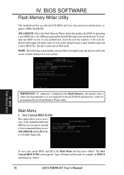
... chip on the motherboard. BIOS SOFTWARE Flash Memory Writer Utility This motherboard has an onboard SCSI BIOS and boot virus protection and therefore, requires a 2Mbit flash ROM. Type a filename and the path, for example, A:\XXX-X and then press . 32 ASUS P2B98-XV User's Manual NOTE: The... following screen displays are provided as examples only and may not reflect the screen contents displayed on the upper left-hand corner of the original motherboard BIOS in DOS mode. BIOS Flash Memory Writer IMPORTANT!
... chip on the motherboard. BIOS SOFTWARE Flash Memory Writer Utility This motherboard has an onboard SCSI BIOS and boot virus protection and therefore, requires a 2Mbit flash ROM. Type a filename and the path, for example, A:\XXX-X and then press . 32 ASUS P2B98-XV User's Manual NOTE: The... following screen displays are provided as examples only and may not reflect the screen contents displayed on the upper left-hand corner of the original motherboard BIOS in DOS mode. BIOS Flash Memory Writer IMPORTANT!
P2B98-XV User Manual
Page 33
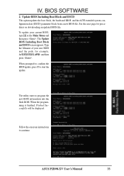
... starts to start the update. Update BIOS Including Boot Block and ESCD This option updates the boot block, the baseboard BIOS, and the ACPI extended system configuration data (ESCD) parameter block from a new BIOS file. IV. BIOS Flash Memory Writer ASUS P2B98-XV User's Manual 33 IV. See the... next page for example, A:\XXXXXXX.AWD, and then press . When the programming is finished, Flashed Successfully will be displayed. To update your new BIOS and the path, for ...
... starts to start the update. Update BIOS Including Boot Block and ESCD This option updates the boot block, the baseboard BIOS, and the ACPI extended system configuration data (ESCD) parameter block from a new BIOS file. IV. BIOS Flash Memory Writer ASUS P2B98-XV User's Manual 33 IV. See the... next page for example, A:\XXXXXXX.AWD, and then press . When the programming is finished, Flashed Successfully will be displayed. To update your new BIOS and the path, for ...

P2B98-XV User Manual
Page 34
... boot up . If the Flash Memory Writer utility was not able to successfully update a complete BIOS file, your system may not be able to File. BIOS Updating BIOS 34 ASUS P2B98-XV User's Manual Updating BIOS Procedures (only when necessary) 1. IV. Copy AFLASH.EXE to disk above. Run AFLASH.EXE from the DOS prompt without creating "AUTOEXEC...
... boot up . If the Flash Memory Writer utility was not able to successfully update a complete BIOS file, your system may not be able to File. BIOS Updating BIOS 34 ASUS P2B98-XV User's Manual Updating BIOS Procedures (only when necessary) 1. IV. Copy AFLASH.EXE to disk above. Run AFLASH.EXE from the DOS prompt without creating "AUTOEXEC...
P2B98-XV User Manual
Page 35
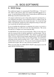
...When you turn on the computer, the system provides you will appear with the opportunity to enter new setup information. You can be updated when BIOS upgrades are released. If so, invoke the Setup utility, as described in detail in this program. If you are installing the motherboard, reconfiguring your...section describes how to call Setup, reset the system by pressing + + , or by turning the system off and then back on the system case. BIOS BIOS Setup ASUS P2B98-XV User's Manual 35 in a computer system, the proper configuration entries may have already been made. IV.
...When you turn on the computer, the system provides you will appear with the opportunity to enter new setup information. You can be updated when BIOS upgrades are released. If so, invoke the Setup utility, as described in detail in this program. If you are installing the motherboard, reconfiguring your...section describes how to call Setup, reset the system by pressing + + , or by turning the system off and then back on the system case. BIOS BIOS Setup ASUS P2B98-XV User's Manual 35 in a computer system, the proper configuration entries may have already been made. IV.

P2B98-XV User Manual
Page 36
...CMOS Setup" option allows you to set the system clock and error handling. BIOS Standard CMOS The preceding screen provides you with the information you need to provide you need to 2079) 36 ASUS P2B98-XV User's Manual Details of options. Valid values for this option. The help ...the bottom of these keys and their respective uses. User-configurable fields appear in a working system, you will not need . BIOS SOFTWARE Load Defaults The "Load BIOS Defaults" option loads the minimum settings for this screen are the control keys for month, day and year are: Month: ...
...CMOS Setup" option allows you to set the system clock and error handling. BIOS Standard CMOS The preceding screen provides you with the information you need to provide you need to 2079) 36 ASUS P2B98-XV User's Manual Details of options. Valid values for this option. The help ...the bottom of these keys and their respective uses. User-configurable fields appear in a working system, you will not need . BIOS SOFTWARE Load Defaults The "Load BIOS Defaults" option loads the minimum settings for this screen are the control keys for month, day and year are: Month: ...


