
P2-99B User Manual
Page 2
... ANY TIME WITHOUT NOTICE, AND SHOULD NOT BE CONSTRUED AS A COMMITMENT BY ASUS. or (2) the serial number of ASUSTeK COMPUTER INC. ("ASUS"). Product Name: ASUS P2-99B Manual Revision: 1.01 E388 Release Date: May 1999 2 ASUS P2-99B User's Manual Product warranty or service will not be extended if: (1) the...form or by any of the means indicated on the product itself. For previous or updated manuals, BIOS, drivers, or product release information, contact ASUS at http://www.asus.com.tw or through any means, except documentation kept by the purchaser for backup purposes, without ...
... ANY TIME WITHOUT NOTICE, AND SHOULD NOT BE CONSTRUED AS A COMMITMENT BY ASUS. or (2) the serial number of ASUSTeK COMPUTER INC. ("ASUS"). Product Name: ASUS P2-99B Manual Revision: 1.01 E388 Release Date: May 1999 2 ASUS P2-99B User's Manual Product warranty or service will not be extended if: (1) the...form or by any of the means indicated on the product itself. For previous or updated manuals, BIOS, drivers, or product release information, contact ASUS at http://www.asus.com.tw or through any means, except documentation kept by the purchaser for backup purposes, without ...

P2-99B User Manual
Page 4
... 5. HARDWARE SETUP 12 Layout of Standard CMOS Setup 42 4 ASUS P2-99B User's Manual BIOS SETUP 38 Flash Memory Writer Utility 38 Main Menu 38 Managing and Updating Your Motherboard's BIOS 40 6. CONTENTS I. BIOS Setup 41 Load Defaults 42 Standard CMOS Setup 42 Details of the ASUS P2-99B Motherboard 12 Hardware Setup Steps 14 1. External Connectors 28 Power...
... 5. HARDWARE SETUP 12 Layout of Standard CMOS Setup 42 4 ASUS P2-99B User's Manual BIOS SETUP 38 Flash Memory Writer Utility 38 Main Menu 38 Managing and Updating Your Motherboard's BIOS 40 6. CONTENTS I. BIOS Setup 41 Load Defaults 42 Standard CMOS Setup 42 Details of the ASUS P2-99B Motherboard 12 Hardware Setup Steps 14 1. External Connectors 28 Power...

P2-99B User Manual
Page 5
... Information 64 Uninstalling Programs 65 VI. APPENDIX 81 The ASUS CIDB Chassis Intrusion Sensor Module 81 The ASUS S370 CPU Card 83 ASUS PCI-L101 Fast Ethernet Card 85 Glossary 87 ASUS P2-99B User's Manual 5 CONTENTS BIOS Features Setup 45 Details of BIOS Features Setup 45 Chipset Features Setup 48 Details of Chipset Features Setup 48 Power...
... Information 64 Uninstalling Programs 65 VI. APPENDIX 81 The ASUS CIDB Chassis Intrusion Sensor Module 81 The ASUS S370 CPU Card 83 ASUS PCI-L101 Fast Ethernet Card 85 Glossary 87 ASUS P2-99B User's Manual 5 CONTENTS BIOS Features Setup 45 Details of BIOS Features Setup 45 Chipset Features Setup 48 Details of Chipset Features Setup 48 Power...
P2-99B User Manual
Page 7
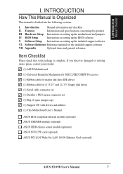
... the following sections: I . INTRODUCTION How This Manual Is Organized This manual is complete. Introduction Manual information and checklist II. BIOS Setup Instructions on setting up the motherboard and jumpers IV. Software Reference Reference material for (1) 5.25" and (2) 3.5" floppy... (1) This Motherboard User's Manual ASUS IrDA-compliant infrared module (optional) ASUS USB/MIR module (optional) ASUS CIDB chassis sensor module (optional) ASUS S370 CPU card (optional) ASUS PCI-L101 Wake-On-LAN 10/100 Ethernet Card (optional) ASUS P2-99B User's Manual 7 Features Information ...
... the following sections: I . INTRODUCTION How This Manual Is Organized This manual is complete. Introduction Manual information and checklist II. BIOS Setup Instructions on setting up the motherboard and jumpers IV. Software Reference Reference material for (1) 5.25" and (2) 3.5" floppy... (1) This Motherboard User's Manual ASUS IrDA-compliant infrared module (optional) ASUS USB/MIR module (optional) ASUS CIDB chassis sensor module (optional) ASUS S370 CPU card (optional) ASUS PCI-L101 Wake-On-LAN 10/100 Ethernet Card (optional) ASUS P2-99B User's Manual 7 Features Information ...
P2-99B User Manual
Page 9
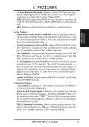
...• Enhanced ACPI and Anti-Boot Virus BIOS: Features a programmable BIOS, offering enhanced ACPI for Windows 98 compatibility, built-in a Single Edge Processor Package (SEPP). • Wake-On-LAN: Supports Wake-On-LAN activity through onboard SYMBIOS firmware. ASUS P2-99B User's Manual 9 FEATURES • Universal Retention..., and 32-bit device drivers and installation procedures for Windows 95/98/NT. • Symbios SCSI BIOS: Supports optional ASUS SCSI controller cards through an optional ASUS PCI-L101 10/100 Fast Ethernet PCI card (See APPENDIX) or a similar ethernet card. •...
...• Enhanced ACPI and Anti-Boot Virus BIOS: Features a programmable BIOS, offering enhanced ACPI for Windows 98 compatibility, built-in a Single Edge Processor Package (SEPP). • Wake-On-LAN: Supports Wake-On-LAN activity through onboard SYMBIOS firmware. ASUS P2-99B User's Manual 9 FEATURES • Universal Retention..., and 32-bit device drivers and installation procedures for Windows 95/98/NT. • Symbios SCSI BIOS: Supports optional ASUS SCSI controller cards through an optional ASUS PCI-L101 10/100 Fast Ethernet PCI card (See APPENDIX) or a similar ethernet card. •...
P2-99B User Manual
Page 10
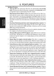
... • Dual Function Power Button: Pushing the power button for less than 4 seconds, the system enters the soft-off mode regardless of the BIOS setting. • Fan Status Monitoring and Alarm (only w/optional hardware monitor): To prevent system overheat and system damage, the CPU, power supply,...resource monitor will give the user information on the BIOS setting (see Power Management Setup under BIOS SETUP). With this benefit on-hand, any user can be powered on remotely through the optional ASUS CIDB module and Intel LDCM. 10 ASUS P2-99B User's Manual All fans are used up to ...
... • Dual Function Power Button: Pushing the power button for less than 4 seconds, the system enters the soft-off mode regardless of the BIOS setting. • Fan Status Monitoring and Alarm (only w/optional hardware monitor): To prevent system overheat and system damage, the CPU, power supply,...resource monitor will give the user information on the BIOS setting (see Power Management Setup under BIOS SETUP). With this benefit on-hand, any user can be powered on remotely through the optional ASUS CIDB module and Intel LDCM. 10 ASUS P2-99B User's Manual All fans are used up to ...

P2-99B User Manual
Page 12
... CHASIS PCI Slot 2 (PCI2) P2-99B Intel PIIX4E CLRTC PCIset CHA_FAN BUS FREQ FS3 FS2 FS1 FS0 SECONDARY IDE PRIMARY IDE Hardware Monitor PCI Slot 3 (PCI3) ISA Slot 1 FREQ MULT IDELED R ASUS ASIC WOR IR ISA Slot 2 2Mbit Flash EEPROM (Programmable BIOS) (The grayed items are optional ...at the time of purchase.) III. H/W SETUP Motherboard Layout BF0 BF1 BF2 BF3 PANEL 12 ASUS P2-99B User's Manual
... CHASIS PCI Slot 2 (PCI2) P2-99B Intel PIIX4E CLRTC PCIset CHA_FAN BUS FREQ FS3 FS2 FS1 FS0 SECONDARY IDE PRIMARY IDE Hardware Monitor PCI Slot 3 (PCI3) ISA Slot 1 FREQ MULT IDELED R ASUS ASIC WOR IR ISA Slot 2 2Mbit Flash EEPROM (Programmable BIOS) (The grayed items are optional ...at the time of purchase.) III. H/W SETUP Motherboard Layout BF0 BF1 BF2 BF3 PANEL 12 ASUS P2-99B User's Manual

P2-99B User Manual
Page 14
H/W SETUP Motherboard Settings III. Setup the BIOS Software 1. Use a grounded wrist strap before handling computer components. The default is set this to Enable and if you want to use of your computer. KBPWR 123 Disable (Default) 123 Enable P2-99B R P2-99B Keyboard Power Up 14 ASUS P2-99B User's Manual HARDWARE SETUP Hardware Setup Steps Before using your...
H/W SETUP Motherboard Settings III. Setup the BIOS Software 1. Use a grounded wrist strap before handling computer components. The default is set this to Enable and if you want to use of your computer. KBPWR 123 Disable (Default) 123 Enable P2-99B R P2-99B Keyboard Power Up 14 ASUS P2-99B User's Manual HARDWARE SETUP Hardware Setup Steps Before using your...

P2-99B User Manual
Page 18
...memory is recommended that SPD DIMMs be available. SPD Support This motherboard supports SPD DIMMs, and it is supported on bootup screen. 18 ASUS P2-99B User's Manual stability. • SDRAM chips are available for 3.3Volt (power level) unbuffered Synchronous Dynamic Random Access Memory (SDRAM). This...ant DIMMs. When this motherboard. Because Socket 3 shares Row 3 with higher pin density than EDO (Extended Data Output) chips. • BIOS shows SDRAM memory on this motherboard operates at 100MHz, most system will not be used if Socket 2 does not use only PC100-compli- ...
...memory is recommended that SPD DIMMs be available. SPD Support This motherboard supports SPD DIMMs, and it is supported on bootup screen. 18 ASUS P2-99B User's Manual stability. • SDRAM chips are available for 3.3Volt (power level) unbuffered Synchronous Dynamic Random Access Memory (SDRAM). This...ant DIMMs. When this motherboard. Because Socket 3 shares Row 3 with higher pin density than EDO (Extended Data Output) chips. • BIOS shows SDRAM memory on this motherboard operates at 100MHz, most system will not be used if Socket 2 does not use only PC100-compli- ...
P2-99B User Manual
Page 26
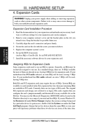
... free. If you removed above. 5. If your power supply when adding or removing expansion cards or other system components. You may use . Set up the BIOS if necessary (such as jumpers. 2. Assigning IRQs for expansion cards. HARDWARE SETUP 4. Secure the card on the ISA bus. Ensure that you intend to do... IRQ xx Used By ISA: Yes in use, leaving 6 IRQs free for Expansion Cards Some expansion cards need to use at the same time. 26 ASUS P2-99B User's Manual III.
... free. If you removed above. 5. If your power supply when adding or removing expansion cards or other system components. You may use . Set up the BIOS if necessary (such as jumpers. 2. Assigning IRQs for expansion cards. HARDWARE SETUP 4. Secure the card on the ISA bus. Ensure that you intend to do... IRQ xx Used By ISA: Yes in use, leaving 6 IRQs free for Expansion Cards Some expansion cards need to use at the same time. 26 ASUS P2-99B User's Manual III.

P2-99B User Manual
Page 27
... from those IRQs and DMAs you need to reserve). H/W SETUP DMA Channels P2-99B R P2-99B Accelerated Graphics Port (AGP) ASUS P2-99B User's Manual 27 If the system has both legacy and PnP, may also need to set to support a new generation of the BIOS Setup utility. IMPORTANT: To avoid conflicts, reserve the necessary IRQs and DMAs...
... from those IRQs and DMAs you need to reserve). H/W SETUP DMA Channels P2-99B R P2-99B Accelerated Graphics Port (AGP) ASUS P2-99B User's Manual 27 If the system has both legacy and PnP, may also need to set to support a new generation of the BIOS Setup utility. IMPORTANT: To avoid conflicts, reserve the necessary IRQs and DMAs...

P2-99B User Manual
Page 29
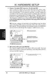
... can make available the serial port and choose the IRQ through "Onboard Parallel Port" in Chipset Features of BIOS SETUP. (Pin 10 is not used. III. Connect the parallel ribbon cable to this connector and mount...in Chipset Features of BIOS SETUP. (Pin 26 is removed to prevent inserting in the wrong orientation when using ribbon cables with pin 10 plugged). P2-99B R P2-99B Serial Port Headers COM 1 COM 2 Pin 1 Pin 1 ASUS P2-99B User's Manual 29... connectors and mount the bracket to Pin 1 Parallel Connector P2-99B R Pin 1 PS/2 Mouse Connector P2-99B Parallel Connector 4.
... can make available the serial port and choose the IRQ through "Onboard Parallel Port" in Chipset Features of BIOS SETUP. (Pin 10 is not used. III. Connect the parallel ribbon cable to this connector and mount...in Chipset Features of BIOS SETUP. (Pin 26 is removed to prevent inserting in the wrong orientation when using ribbon cables with pin 10 plugged). P2-99B R P2-99B Serial Port Headers COM 1 COM 2 Pin 1 Pin 1 ASUS P2-99B User's Manual 29... connectors and mount the bracket to Pin 1 Parallel Connector P2-99B R Pin 1 PS/2 Mouse Connector P2-99B Parallel Connector 4.
P2-99B User Manual
Page 30
... IDE connectors will cause the LED to Slave mode by setting its jumper accordingly. H/W SETUP Connectors P2-99B R P2-99B IDE Activity LED IDELED 30 ASUS P2-99B User's Manual Primary / Secondary IDE Connectors (Two 40-1 pin IDE) These connectors support the provided... IDE hard disk ribbon cable. TIP: You may install up . III. You may configure two hard disks to four operating systems on each IDE drive and select the boot disk through "Boot Sequence" in BIOS...
... IDE connectors will cause the LED to Slave mode by setting its jumper accordingly. H/W SETUP Connectors P2-99B R P2-99B IDE Activity LED IDELED 30 ASUS P2-99B User's Manual Primary / Secondary IDE Connectors (Two 40-1 pin IDE) These connectors support the provided... IDE hard disk ribbon cable. TIP: You may install up . III. You may configure two hard disks to four operating systems on each IDE drive and select the boot disk through "Boot Sequence" in BIOS...

P2-99B User Manual
Page 31
... under BIOS SETUP) and that your system has an ATX power supply with at least 720mA +5V standby power. The red wire should be positive, while the black should be different. CPU Fan Power (CPU_FAN) Power Supply Fan (PWR_FAN) GND +12V Rotation P2-99B R P2-99B 12Volt ...LAN Connector (3-pin WOL_CON) This connector connects to the board taking into consideration the polarity of the expansion slots. P2-99B R Ground +5 VSB PME P2-99B Wake-On-LAN Connector ASUS P2-99B User's Manual 31 Damage may be ground. IMPORTANT: This feature requires that the heat sink fins allow airflow to...
... under BIOS SETUP) and that your system has an ATX power supply with at least 720mA +5V standby power. The red wire should be positive, while the black should be different. CPU Fan Power (CPU_FAN) Power Supply Fan (PWR_FAN) GND +12V Rotation P2-99B R P2-99B 12Volt ...LAN Connector (3-pin WOL_CON) This connector connects to the board taking into consideration the polarity of the expansion slots. P2-99B R Ground +5 VSB PME P2-99B Wake-On-LAN Connector ASUS P2-99B User's Manual 31 Damage may be ground. IMPORTANT: This feature requires that the heat sink fins allow airflow to...

P2-99B User Manual
Page 32
... allow wakeup (the SMI lead cannot wake-up can be controlled by settings in Power Management Setup of BIOS SETUP section should be instantly decreased to manually place the system into a suspend mode or "Green" mode... This 2-pin connector connects to the case-mounted key switch to this connector, "Suspend Switch" in the BIOS but the keyboard will remain lit when there is no signal and blink when there is data transfer or...in sleep mode. 14. This function requires ACPI OS support. 10. P2-99B System Panel Connections 32 ASUS P2-99B User's Manual III. If you may use .
... allow wakeup (the SMI lead cannot wake-up can be controlled by settings in Power Management Setup of BIOS SETUP section should be instantly decreased to manually place the system into a suspend mode or "Green" mode... This 2-pin connector connects to the case-mounted key switch to this connector, "Suspend Switch" in the BIOS but the keyboard will remain lit when there is no signal and blink when there is data transfer or...in sleep mode. 14. This function requires ACPI OS support. 10. P2-99B System Panel Connections 32 ASUS P2-99B User's Manual III. If you may use .

P2-99B User Manual
Page 33
...Module Connector Front View Back View IRTX GND IRRX +5V (NC) ASUS P2-99B User's Manual 33 HARDWARE SETUP 16. You must also configure the setting through "UART2 Use Infrared" in PnP and PCI Setup of BIOS SETUP. USB, Infrared, PS/2 Mouse Module Connector (18-1 pin USB... one is directed for details on system cases that support this feature. USB/MIR 9 18 Parallel Connector Infrared PS/2 Mouse 1 10 PS/2 Mouse Connector USB 0 P2-99B R 9: +5 Volt 8: (no connection) 7: Ground 6: PS/2 Mouse Clock 5: USB +5 Volt 4: Ground 3: USB Port 0 + 2: USB Port 0 1: USB +5 Volt 18: ...
...Module Connector Front View Back View IRTX GND IRRX +5V (NC) ASUS P2-99B User's Manual 33 HARDWARE SETUP 16. You must also configure the setting through "UART2 Use Infrared" in PnP and PCI Setup of BIOS SETUP. USB, Infrared, PS/2 Mouse Module Connector (18-1 pin USB... one is directed for details on system cases that support this feature. USB/MIR 9 18 Parallel Connector Infrared PS/2 Mouse 1 10 PS/2 Mouse Connector USB 0 P2-99B R 9: +5 Volt 8: (no connection) 7: Ground 6: PS/2 Mouse Clock 5: USB +5 Volt 4: Ground 3: USB Port 0 + 2: USB Port 0 1: USB +5 Volt 18: ...

P2-99B User Manual
Page 34
... is triggered. III. III. HARDWARE SETUP 18. P2-99B R WOR Pin 2 PIXRI# Pin 1 Ground P2-99B Wake-On-Ring Connector 19. This function requires the optional ASUS CIDB Chassis Intrusion Photo Sensor Module (see Power Management Setup under BIOS SETUP) and that PWR UP On Modem Act Power... Up Control is sent to Enabled (see APPENDIX) to an internal modem card with at least 720mA +5V standby power. H/W SETUP Connectors +5Volt (Power Supply Stand By) Chassis Signal Ground P2-99B R P2-99B Chassis Open Alarm Lead 34 ASUS P2-99B...
... is triggered. III. III. HARDWARE SETUP 18. P2-99B R WOR Pin 2 PIXRI# Pin 1 Ground P2-99B Wake-On-Ring Connector 19. This function requires the optional ASUS CIDB Chassis Intrusion Photo Sensor Module (see Power Management Setup under BIOS SETUP) and that PWR UP On Modem Act Power... Up Control is sent to Enabled (see APPENDIX) to an internal modem card with at least 720mA +5V standby power. H/W SETUP Connectors +5Volt (Power Supply Stand By) Chassis Signal Ground P2-99B R P2-99B Chassis Open Alarm Lead 34 ASUS P2-99B...

P2-99B User Manual
Page 37
... provided as well as press the ATX power switch on the front of your system case according to the power supply located on the screen. ASUS P2-99B User's Manual 37 Connect the power supply cord to your devices in the following order: a. Your system power. For ATX power supplies, the system LED... (starting with ATX power supplies. The power supply should turn off the power switch. HARDWARE SETUP Power Connection Procedures 1. Connect the power cord to enter BIOS setup. If you can now safely turn off (in the next section...
... provided as well as press the ATX power switch on the front of your system case according to the power supply located on the screen. ASUS P2-99B User's Manual 37 Connect the power supply cord to your devices in the following order: a. Your system power. For ATX power supplies, the system LED... (starting with ATX power supplies. The power supply should turn off the power switch. HARDWARE SETUP Power Connection Procedures 1. Connect the power cord to enter BIOS setup. If you can now safely turn off (in the next section...

P2-99B User Manual
Page 38
...uploading a new BIOS file to the programmable flash ROM chip on your current BIOS, type [1] at the Main Menu and then press . To save AFLASH.EXE and the BIOS file to reinstall it. IV. Type a filename and the path, for example, A:\XXX-XX.XXX and then press . 38 ASUS P2-99B User's Manual ...To determine the BIOS version of your screen during bootup. NOTE: The following screen displays are provided as examples only and may not reflect the screen contents...
...uploading a new BIOS file to the programmable flash ROM chip on your current BIOS, type [1] at the Main Menu and then press . To save AFLASH.EXE and the BIOS file to reinstall it. IV. Type a filename and the path, for example, A:\XXX-XX.XXX and then press . 38 ASUS P2-99B User's Manual ...To determine the BIOS version of your screen during bootup. NOTE: The following screen displays are provided as examples only and may not reflect the screen contents...

P2-99B User Manual
Page 39
... Block and ESCD This option updates the boot block, the baseboard BIOS, and the ACPI extended system configuration data (ESCD) parameter block from a new BIOS file. BIOS SETUP Flash Memory Writer ASUS P2-99B User's Manual 39 BIOS SETUP 2. Follow the onscreen instructions to program the new BIOS information into the flash ROM. See the next page for...
... Block and ESCD This option updates the boot block, the baseboard BIOS, and the ACPI extended system configuration data (ESCD) parameter block from a new BIOS file. BIOS SETUP Flash Memory Writer ASUS P2-99B User's Manual 39 BIOS SETUP 2. Follow the onscreen instructions to program the new BIOS information into the flash ROM. See the next page for...


