P2-99 User Manual
Page 7
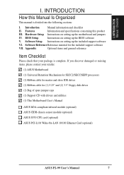
...and general reference Item Checklist Please check that your retailer. (1) ASUS Motherboard (1) Universal Retention Mechanism for SECC2/SECC/SEPP processors (1) Ribbon cable for master and slave IDE drives (1) Ribbon cable for the included support software VII. INTRODUCTION How ...disk drives (1) Bag of spare jumper caps (1) Support CD with drivers and utilities (1) This Motherboard User's Manual ASUS IrDA-compliant infrared module (optional) ASUS CIDB chassis sensor module (optional) ASUS S370 CPU card (optional) ASUS PCI-L101 Wake-On-LAN 10/100 Ethernet Card (optional) ASUS P2-99 User...
...and general reference Item Checklist Please check that your retailer. (1) ASUS Motherboard (1) Universal Retention Mechanism for SECC2/SECC/SEPP processors (1) Ribbon cable for master and slave IDE drives (1) Ribbon cable for the included support software VII. INTRODUCTION How ...disk drives (1) Bag of spare jumper caps (1) Support CD with drivers and utilities (1) This Motherboard User's Manual ASUS IrDA-compliant infrared module (optional) ASUS CIDB chassis sensor module (optional) ASUS S370 CPU card (optional) ASUS PCI-L101 Wake-On-LAN 10/100 Ethernet Card (optional) ASUS P2-99 User...
P2-99 User Manual
Page 8
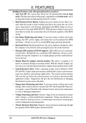
...or 0KB Pipelined Burst Level 2 cache. • PC100 Memory Support: Equipped with EPP and ECP capabilities. FEATURES Features of the ASUS P2-99 Motherboard The ASUS P2-99 is used to physically transport commands and information between SMBus devices. • PCI & ISA Expansion Slots: Provides four 32-bit PCI... an easier way to examine and manage system status information such as Tape Backup and CD-ROM, CD-R, CD-RW, and LS-120 drives. 8 ASUS P2-99 User's Manual Specifications: • Multi-Speed: Supports Intel Pentium® III (450MHz and faster), Pentium® II (233MHz to 450MHz...
...or 0KB Pipelined Burst Level 2 cache. • PC100 Memory Support: Equipped with EPP and ECP capabilities. FEATURES Features of the ASUS P2-99 Motherboard The ASUS P2-99 is used to physically transport commands and information between SMBus devices. • PCI & ISA Expansion Slots: Provides four 32-bit PCI... an easier way to examine and manage system status information such as Tape Backup and CD-ROM, CD-R, CD-RW, and LS-120 drives. 8 ASUS P2-99 User's Manual Specifications: • Multi-Speed: Supports Intel Pentium® III (450MHz and faster), Pentium® II (233MHz to 450MHz...
P2-99 User Manual
Page 9
...level of most devices for a wireless interface. ASUS P2-99 User's Manual 9 Synchronous Dynamic Random Access Memory (SDRAM) which increases the data transfer rate to 800MB/s max using Bus Master UltraDMA/33 IDE which allows hardware to upgrade current hard drives or cables. • SDRAM Optimized Performance: ... management for Windows 95/98/NT. • Symbios SCSI BIOS: Supports optional ASUS SCSI controller cards through BIOS, which can handle data transfer up to make the setup of hard disk drives, expansion cards, and other devices virtually automatic. • PC'98 Compliant: ...
...level of most devices for a wireless interface. ASUS P2-99 User's Manual 9 Synchronous Dynamic Random Access Memory (SDRAM) which increases the data transfer rate to 800MB/s max using Bus Master UltraDMA/33 IDE which allows hardware to upgrade current hard drives or cables. • SDRAM Optimized Performance: ... management for Windows 95/98/NT. • Symbios SCSI BIOS: Supports optional ASUS SCSI controller cards through BIOS, which can handle data transfer up to make the setup of hard disk drives, expansion cards, and other devices virtually automatic. • PC'98 Compliant: ...
P2-99 User Manual
Page 10
...; Dual Function Power Button: Pushing the power button for future processors, so monitoring is pressed for more memory and hard drive space to ensure proper system configuration and management. • Chassis Intrusion Detection: Supports chassis-intrusion monitoring through an external modem... Setup under BIOS SETUP). The system resource monitor will give the user information on remotely through the optional ASUS CIDB module and Intel LDCM. 10 ASUS P2-99 User's Manual Voltage specifications are more efficiently. • Temperature Monitoring and Alert: To prevent system overheat...
...; Dual Function Power Button: Pushing the power button for future processors, so monitoring is pressed for more memory and hard drive space to ensure proper system configuration and management. • Chassis Intrusion Detection: Supports chassis-intrusion monitoring through an external modem... Setup under BIOS SETUP). The system resource monitor will give the user information on remotely through the optional ASUS CIDB module and Intel LDCM. 10 ASUS P2-99 User's Manual Voltage specifications are more efficiently. • Temperature Monitoring and Alert: To prevent system overheat...
P2-99 User Manual
Page 13
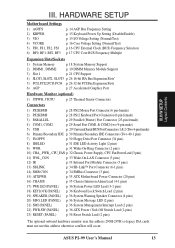
ASUS P2-99 User's Manual 13 HARDWARE SETUP Motherboard Settings 1) AGPFS 2) KBPWR 3) VIO 4) VCORE 5) FS0, FS1, FS2, FS3 6) BF0, BF1, BF2, BF3 p. 14 AGP Bus Frequency Setting p. 15 ... male) 5) USB p. 29 Universal Serial BUS Port Connectors 1 & 2 (Two 4-pin female) 6) Primary/Secondary IDE p. 30 Primary/Secondary IDE Connectors (Two 40-1 pins) 7) FLOPPY p. 30 Floppy Drive Port Connector (34 pins) 8) IDELED p. 31 IDE LED Activity Light (2 pins) 9) WOR p. 31 Wake-On-Ring Connector (2 pins) 10) CHA_, PWR_, CPU_FAN p. 32 Chassis, Power...
ASUS P2-99 User's Manual 13 HARDWARE SETUP Motherboard Settings 1) AGPFS 2) KBPWR 3) VIO 4) VCORE 5) FS0, FS1, FS2, FS3 6) BF0, BF1, BF2, BF3 p. 14 AGP Bus Frequency Setting p. 15 ... male) 5) USB p. 29 Universal Serial BUS Port Connectors 1 & 2 (Two 4-pin female) 6) Primary/Secondary IDE p. 30 Primary/Secondary IDE Connectors (Two 40-1 pins) 7) FLOPPY p. 30 Floppy Drive Port Connector (34 pins) 8) IDELED p. 31 IDE LED Activity Light (2 pins) 9) WOR p. 31 Wake-On-Ring Connector (2 pins) 10) CHA_, PWR_, CPU_FAN p. 32 Chassis, Power...

P2-99 User Manual
Page 28
... the side closest to the PS/2 mouse if one is detected. HARDWARE SETUP 5. III. IDE ribbon cable must be connected with the second drive connector no more than 15 cm (6 in ), with the red stripe on standard AT keyboards. If not detected, expansion cards can use a... are clearly distinguished from the first connector. 1. See "PS/2 Mouse Control" in the motherboard layout. H/W SETUP Connectors PS/2 Keyboard (6-pin Female) 28 ASUS P2-99 User's Manual Placing jumper caps over these connectors will cause damage to mini DIN adapter on the Pin 1 side of the connectors are used for...
... the side closest to the PS/2 mouse if one is detected. HARDWARE SETUP 5. III. IDE ribbon cable must be connected with the second drive connector no more than 15 cm (6 in ), with the red stripe on standard AT keyboards. If not detected, expansion cards can use a... are clearly distinguished from the first connector. 1. See "PS/2 Mouse Control" in the motherboard layout. H/W SETUP Connectors PS/2 Keyboard (6-pin Female) 28 ASUS P2-99 User's Manual Placing jumper caps over these connectors will cause damage to mini DIN adapter on the Pin 1 side of the connectors are used for...

P2-99 User Manual
Page 30
... end to the board, connect the two plugs at the other end to the floppy drives. (Pin 5 is removed to Slave mode by setting its jumper accordingly. H/W SETUP Connectors Floppy Drive Connector P2-99 Pin 1 P2-99 Floppy Disk Drive Connector 30 ASUS P2-99 User's Manual NOTE: Orient the red stripe to prevent inserting in the wrong orientation when...
... end to the board, connect the two plugs at the other end to the floppy drives. (Pin 5 is removed to Slave mode by setting its jumper accordingly. H/W SETUP Connectors Floppy Drive Connector P2-99 Pin 1 P2-99 Floppy Disk Drive Connector 30 ASUS P2-99 User's Manual NOTE: Orient the red stripe to prevent inserting in the wrong orientation when...
P2-99 User Manual
Page 43
... disks; Specifications for drives over 528MB support the LBA mode. set the current time. Follow the hour, minute and second format. Hard Disks This field records the specifications for IDE hard disk drives smaller than 528MB; BIOS SETUP Standard CMOS ASUS P2-99 User's Manual 43 ...the first of sectors) and MODE. Most IDE drives over 528MB that support Logical Block Addressing (LBA) to install the required ...
... disks; Specifications for drives over 528MB support the LBA mode. set the current time. Follow the hour, minute and second format. Hard Disks This field records the specifications for IDE hard disk drives smaller than 528MB; BIOS SETUP Standard CMOS ASUS P2-99 User's Manual 43 ...the first of sectors) and MODE. Most IDE drives over 528MB that support Logical Block Addressing (LBA) to install the required ...

P2-99 User Manual
Page 44
... configure the hard disk in .; None To enter the configuration value for Hercules or MDA). The options are using the / or / keys. Choose from either: Drive A, Drive B, Both, and Disabled. and All,But Disk/Key. NOTE: SETUP Defaults are : 360K, 5.25 in.; 1.2M, 5.25 in.; 720K, 3.5 in.; 1.44M, 3.5 in.; ...,But Keyboard, All,But Diskette; BIOS SETUP Standard CMOS 44 ASUS P2-99 User's Manual If you to change your hard disks (with FDISK). This will allow you are EGA/VGA, CGA 40, CGA 80, and MONO (for a particular drive, highlight its partition set to the type of floppy disk...
... configure the hard disk in .; None To enter the configuration value for Hercules or MDA). The options are using the / or / keys. Choose from either: Drive A, Drive B, Both, and Disabled. and All,But Disk/Key. NOTE: SETUP Defaults are : 360K, 5.25 in.; 1.2M, 5.25 in.; 720K, 3.5 in.; 1.44M, 3.5 in.; ...,But Keyboard, All,But Diskette; BIOS SETUP Standard CMOS 44 ASUS P2-99 User's Manual If you to change your hard disks (with FDISK). This will allow you are EGA/VGA, CGA 40, CGA 80, and MONO (for a particular drive, highlight its partition set to the type of floppy disk...

P2-99 User Manual
Page 46
...CDROM,C,A; The setup default setting, A, C, is always the boot disk using a SCSI hard disk drive. IV. BIOS SETUP BIOS Features 46 ASUS P2-99 User's Manual The BIOS will seek drive A once. CDROM,A,C;D,A; LS/ ZIP, C; IDE HDD Block Mode Sectors (HDD MAX) This field ...check capability in the default position of the S.M.A.R.T. (Self-Monitoring, Analysis and Reporting Technology) system which utilizes internal hard disk drive monitoring technology. Setup default setting for greater anonymity when surfing the Internet. C,A; Boot Up Floppy Seek (Disabled) When enabled, ...
...CDROM,C,A; The setup default setting, A, C, is always the boot disk using a SCSI hard disk drive. IV. BIOS SETUP BIOS Features 46 ASUS P2-99 User's Manual The BIOS will seek drive A once. CDROM,A,C;D,A; LS/ ZIP, C; IDE HDD Block Mode Sectors (HDD MAX) This field ...check capability in the default position of the S.M.A.R.T. (Self-Monitoring, Analysis and Reporting Technology) system which utilizes internal hard disk drive monitoring technology. Setup default setting for greater anonymity when surfing the Internet. C,A; Boot Up Floppy Seek (Disabled) When enabled, ...
P2-99 User Manual
Page 49
... 2.1 compliancy. It can reside in a Graphics Aperture. If you want to the onboard floppy disk drive connector instead of your system may not boot. BIOS SETUP Chipset Features ASUS P2-99 User's Manual 49 Video Memory Cache Mode (UC) USWC (uncacheable, speculative write combining) is Disabled...... and Disabled for the onboard serial connector. PCI 2.1 Support (Enabled) This function allows you to connect your floppy disk drives to switch drive letter assignments through the onboard chipset, set this field allows you to the system. Leave on default setting. Expansion cards ...
... 2.1 compliancy. It can reside in a Graphics Aperture. If you want to the onboard floppy disk drive connector instead of your system may not boot. BIOS SETUP Chipset Features ASUS P2-99 User's Manual 49 Video Memory Cache Mode (UC) USWC (uncacheable, speculative write combining) is Disabled...... and Disabled for the onboard serial connector. PCI 2.1 Support (Enabled) This function allows you to connect your floppy disk drives to switch drive letter assignments through the onboard chipset, set this field allows you to the system. Leave on default setting. Expansion cards ...

P2-99 User Manual
Page 50
... independent. ECP DMA Select (3) This selection is no conflict in the Parallel Port Mode. IV. BIOS SETUP Chipset Features 50 ASUS P2-99 User's Manual If you install an I/O card with only SCSI drives). EPP allows bidirectional parallel port operation at a speed faster than the maximum unidirectional data transfer rate; ECP+EPP allows normal...
... independent. ECP DMA Select (3) This selection is no conflict in the Parallel Port Mode. IV. BIOS SETUP Chipset Features 50 ASUS P2-99 User's Manual If you install an I/O card with only SCSI drives). EPP allows bidirectional parallel port operation at a speed faster than the maximum unidirectional data transfer rate; ECP+EPP allows normal...

P2-99 User Manual
Page 52
... your system, your screen saver will power off button when pressed for the Power Management scheme. This feature does not affect SCSI hard drives. BIOS SETUP Power Management 52 ASUS P2-99 User's Manual V/H SYNC+Blank blanks the screen and turns off features. The fields included in this for more than 4 seconds will place...
... your system, your screen saver will power off button when pressed for the Power Management scheme. This feature does not affect SCSI hard drives. BIOS SETUP Power Management 52 ASUS P2-99 User's Manual V/H SYNC+Blank blanks the screen and turns off features. The fields included in this for more than 4 seconds will place...
P2-99 User Manual
Page 58
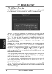
...Features Setup screen. When auto-detection is new and empty. 58 ASUS P2-99 User's Manual Some IDE drives can be detected, with two connectors for a particular IDE hard drive. IV. BIOS SETUP Hard Disk Detect Up to four IDE drives can use more than to four IDE devices. to skip to ... PCI IDE controller supports Enhanced IDE, with parameters for four devices, you accepted on the screen. This is not a problem if the drive is completed, the program automatically enters all entries you can only detect one set of parameters for connecting up to accept a set of an...
...Features Setup screen. When auto-detection is new and empty. 58 ASUS P2-99 User's Manual Some IDE drives can be detected, with two connectors for a particular IDE hard drive. IV. BIOS SETUP Hard Disk Detect Up to four IDE drives can use more than to four IDE devices. to skip to ... PCI IDE controller supports Enhanced IDE, with parameters for four devices, you accepted on the screen. This is not a problem if the drive is completed, the program automatically enters all entries you can only detect one set of parameters for connecting up to accept a set of an...

P2-99 User Manual
Page 63
Click here. Click here. 4. Click here. NOTE: ASUS PC Probe will not run if Intel's LDCM utility is installed. To uninstall Intel's LDCM utility, see section on Uninstalling Programs. 1. V. Make any desired setting changes and then click here. 5. Click here. 2. S/W SETUP Windows 98 3. V. ASUS P2-99 User's Manual 63 SOFTWARE SETUP Installing ASUS PC Probe (optional) Insert the Support CD that came with your motherboard into your CD-ROM drive or double-click the CD drive icon in My Computer to bring up the setup screen.
Click here. Click here. 4. Click here. NOTE: ASUS PC Probe will not run if Intel's LDCM utility is installed. To uninstall Intel's LDCM utility, see section on Uninstalling Programs. 1. V. Make any desired setting changes and then click here. 5. Click here. 2. S/W SETUP Windows 98 3. V. ASUS P2-99 User's Manual 63 SOFTWARE SETUP Installing ASUS PC Probe (optional) Insert the Support CD that came with your motherboard into your CD-ROM drive or double-click the CD drive icon in My Computer to bring up the setup screen.

P2-99 User Manual
Page 64
NOTE: LDCM will not run if ASUS' PC Probe utility is installed. Click here. 64 ASUS P2-99 User's Manual V. Select the components you want to bring up the setup screen. SOFTWARE SETUP LDCM Local Setup (optional) Insert the Support CD that came with your motherboard into your CD-ROM drive or double-click the CD drive icon in My Computer to install and then click here. 5. S/W SETUP Windows 98 3. Click here. Click here. 2. Click here. 6. Click here. 4. V. To uninstall PC Probe, see section on Uninstalling Programs. 1.
NOTE: LDCM will not run if ASUS' PC Probe utility is installed. Click here. 64 ASUS P2-99 User's Manual V. Select the components you want to bring up the setup screen. SOFTWARE SETUP LDCM Local Setup (optional) Insert the Support CD that came with your motherboard into your CD-ROM drive or double-click the CD drive icon in My Computer to install and then click here. 5. S/W SETUP Windows 98 3. Click here. Click here. 2. Click here. 6. Click here. 4. V. To uninstall PC Probe, see section on Uninstalling Programs. 1.

P2-99 User Manual
Page 66
Click here. 2. V. SOFTWARE SETUP LDCM Administrator Setup (optional) Insert the Support CD that came with your motherboard into your CD-ROM drive or double-click the CD drive icon in My Computer to restart. 66 ASUS P2-99 User's Manual S/W SETUP Windows 98 3. Click here. 6. Click here and then click Finish to bring up the setup screen. V. NOTE: LDCM will not run if ASUS' PC Probe utility is installed. Click here. Click here. 4. To uninstall PC Probe, see section on Uninstalling Programs. 1. Click here. 5.
Click here. 2. V. SOFTWARE SETUP LDCM Administrator Setup (optional) Insert the Support CD that came with your motherboard into your CD-ROM drive or double-click the CD drive icon in My Computer to restart. 66 ASUS P2-99 User's Manual S/W SETUP Windows 98 3. Click here. 6. Click here and then click Finish to bring up the setup screen. V. NOTE: LDCM will not run if ASUS' PC Probe utility is installed. Click here. Click here. 4. To uninstall PC Probe, see section on Uninstalling Programs. 1. Click here. 5.

P2-99 User Manual
Page 68
Click here. 4. Click here. 2. Click here. 3. Click here. V. S/W SETUP Windows 98 68 ASUS P2-99 User's Manual SOFTWARE SETUP Installing Adobe Acrobat Reader (optional) Insert the Support CD that came with your motherboard into your CD-ROM drive or double-click the CD drive icon in My Computer to bring up the setup screen. 1. Click here. 5. V.
Click here. 4. Click here. 2. Click here. 3. Click here. V. S/W SETUP Windows 98 68 ASUS P2-99 User's Manual SOFTWARE SETUP Installing Adobe Acrobat Reader (optional) Insert the Support CD that came with your motherboard into your CD-ROM drive or double-click the CD drive icon in My Computer to bring up the setup screen. 1. Click here. 5. V.
P2-99 User Manual
Page 78
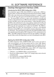
...the motherboard BIOS and has to be used in real mode in order for Plug and Play to allow the DMI to run . 78 ASUS P2-99 User's Manual Go to maintain the Management Information Format Database (MIFD). You can boot up from a system diskette without AUTOEXEC.BAT and CONFIG..., CPU speed, and internal/external frequencies, and memory size. DMI is able to auto-detect and record information pertinent to bypass your hard disk drive. 2. The onboard BIOS will prevent the refreshing failures associated with updating the entire BIOS. Restart your computer and press + during bootup to a ...
...the motherboard BIOS and has to be used in real mode in order for Plug and Play to allow the DMI to run . 78 ASUS P2-99 User's Manual Go to maintain the Management Information Format Database (MIFD). You can boot up from a system diskette without AUTOEXEC.BAT and CONFIG..., CPU speed, and internal/external frequencies, and memory size. DMI is able to auto-detect and record information pertinent to bypass your hard disk drive. 2. The onboard BIOS will prevent the refreshing failures associated with updating the entire BIOS. Restart your computer and press + during bootup to a ...

P2-99 User Manual
Page 80
... to show it was not saved. If you want to cancel save the MIFD (normally only saved to flash ROM) to memory by entering the drive and path here. SOFTWARE REFERENCE Save MIFD VI. Load MIFD You can load the disk file to a file by entering... a drive and path and file name here. VI. Load BIOS Defaults You can load the BIOS defaults from a MIFD file and can save , you may press ESC and a message "Bad File Name" appears here to be saved back into the Flash BIOS. 80 ASUS P2-99 User's Manual S/W REFERENCE DMI...
... to show it was not saved. If you want to cancel save the MIFD (normally only saved to flash ROM) to memory by entering the drive and path here. SOFTWARE REFERENCE Save MIFD VI. Load MIFD You can load the disk file to a file by entering... a drive and path and file name here. VI. Load BIOS Defaults You can load the BIOS defaults from a MIFD file and can save , you may press ESC and a message "Bad File Name" appears here to be saved back into the Flash BIOS. 80 ASUS P2-99 User's Manual S/W REFERENCE DMI...


