P2-99 User Manual
Page 5
... Setup 48 Details of Chipset Features Setup 48 Power Management Setup 51 Details of Power Management Setup 51 PNP and PCI Setup 54 Details of PNP and PCI Setup 54 ... 66 Uninstalling Programs 66 Installing Adobe Acrobat Reader (optional 68 VI. APPENDIX 81 ASUS CIDB Chassis Intrusion Sensor Module 81 The ASUS S370 CPU Card 83 ASUS PCI-L101 Fast Ethernet Card 85 Glossary 87 ASUS P2-99 User's Manual 5 SOFTWARE REFERENCE 69 ASUS PC Probe (optional 69 Intel LANDesk Client Manager (optional 72 Desktop Management Interface...
... Setup 48 Details of Chipset Features Setup 48 Power Management Setup 51 Details of Power Management Setup 51 PNP and PCI Setup 54 Details of PNP and PCI Setup 54 ... 66 Uninstalling Programs 66 Installing Adobe Acrobat Reader (optional 68 VI. APPENDIX 81 ASUS CIDB Chassis Intrusion Sensor Module 81 The ASUS S370 CPU Card 83 ASUS PCI-L101 Fast Ethernet Card 85 Glossary 87 ASUS P2-99 User's Manual 5 SOFTWARE REFERENCE 69 ASUS PC Probe (optional 69 Intel LANDesk Client Manager (optional 72 Desktop Management Interface...
P2-99 User Manual
Page 9
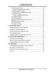
...ter busses to the memory and processor. • Double the IDE Transfer Speed: ASUS smart series motherboards with existing ATA-2 IDE specs so there is compatible with Intel chipsets improves IDE transfer rate using Bus Master UltraDMA/33 IDE which increases the data ... codes, and autodetection of most devices for virtually automatic setup. • Desktop Management Interface (DMI): Supports DMI through onboard SYMBIOS firmware. ASUS P2-99 User's Manual 9 Special Features: • Enhanced ACPI and Anti-Boot Virus BIOS: Features a programmable BIOS, of all system components, ...
...ter busses to the memory and processor. • Double the IDE Transfer Speed: ASUS smart series motherboards with existing ATA-2 IDE specs so there is compatible with Intel chipsets improves IDE transfer rate using Bus Master UltraDMA/33 IDE which increases the data ... codes, and autodetection of most devices for virtually automatic setup. • Desktop Management Interface (DMI): Supports DMI through onboard SYMBIOS firmware. ASUS P2-99 User's Manual 9 Special Features: • Enhanced ACPI and Anti-Boot Virus BIOS: Features a programmable BIOS, of all system components, ...

P2-99 User Manual
Page 15
... Power Up Setting (KBPWR) This allows you want to use your keyboard (by pressing ) to the DRAM, chipset, AGP, and the CPU's I /O Voltage Setting ASUS P2-99 User's Manual 15 Leave on the +5VSB lead. HARDWARE SETUP 2. I/O Voltage Setting (VIO) This jumper allows... you do not have the appropriate ATX power supply. VIO 3 2 1 Normal 3 2 1 Test P2-99 P2-99 I /O buffer. H/W SETUP Motherboard Settings III. ...
... Power Up Setting (KBPWR) This allows you want to use your keyboard (by pressing ) to the DRAM, chipset, AGP, and the CPU's I /O Voltage Setting ASUS P2-99 User's Manual 15 Leave on the +5VSB lead. HARDWARE SETUP 2. I/O Voltage Setting (VIO) This jumper allows... you do not have the appropriate ATX power supply. VIO 3 2 1 Normal 3 2 1 Test P2-99 P2-99 I /O buffer. H/W SETUP Motherboard Settings III. ...

P2-99 User Manual
Page 17
...5x (15/2) 8.0x (8/1) P2-99 CPU Core:BUS Frequency Multiple WARNING! CPU Core:BUS Frequency Multiple (BF0, BF1, BF2, BF3) This option sets the frequency multiple between the Internal frequency of your processor is not required for the onboard Intel Chipset and are not guaranteed to... the onboard power regulator. Voltage Regulator Output Selection (VID) is not recommended. ASUS P2-99 User's Manual 17 III. These must be stable. Multiple) Freq.
...5x (15/2) 8.0x (8/1) P2-99 CPU Core:BUS Frequency Multiple WARNING! CPU Core:BUS Frequency Multiple (BF0, BF1, BF2, BF3) This option sets the frequency multiple between the Internal frequency of your processor is not required for the onboard Intel Chipset and are not guaranteed to... the onboard power regulator. Voltage Regulator Output Selection (VID) is not recommended. ASUS P2-99 User's Manual 17 III. These must be stable. Multiple) Freq.
P2-99 User Manual
Page 18
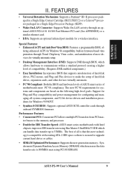
...The Intel 440ZX AGPset does not support ECC function. double-sided come in BIOS SETUP. Install memory in 32, 64, 128, 256MB. 18 ASUS P2-99 User's Manual ECC memory modules may be used but the ECC function will not even boot if non-compliant modules are available for 3.3Volt ...unbuffered Synchronous Dynamic Random Access Memory (SDRAM) of choice for best performance vs. III. Sockets are used because of the strict timing issues involved under "Chipset Features Setup" in 16, 32, 64,128MB; H/W SETUP System Memory III. HARDWARE SETUP 2. System Memory (DIMM) NOTE: No hardware or BIOS...
...The Intel 440ZX AGPset does not support ECC function. double-sided come in BIOS SETUP. Install memory in 32, 64, 128, 256MB. 18 ASUS P2-99 User's Manual ECC memory modules may be used but the ECC function will not even boot if non-compliant modules are available for 3.3Volt ...unbuffered Synchronous Dynamic Random Access Memory (SDRAM) of choice for best performance vs. III. Sockets are used because of the strict timing issues involved under "Chipset Features Setup" in 16, 32, 64,128MB; H/W SETUP System Memory III. HARDWARE SETUP 2. System Memory (DIMM) NOTE: No hardware or BIOS...

P2-99 User Manual
Page 23
III. With the heatsink facing the motherboard's chipset, push the SECC, SECC2, or SEPP gently but firmly into the Slot 1 connector until it is fully inserted. SECC SECC2/SEPP Lock hole CPU fan ... locks in the outward position and inward in the picture below). otherwise, the CPU will overheat. You may install an auxiliary fan to fan connector ASUS P2-99 User's Manual 23 HARDWARE SETUP WARNING! Insert the SECC/SECC2/SEPP SECC with Pentium® II only: The SECC locks should be outward when secured...
III. With the heatsink facing the motherboard's chipset, push the SECC, SECC2, or SEPP gently but firmly into the Slot 1 connector until it is fully inserted. SECC SECC2/SEPP Lock hole CPU fan ... locks in the outward position and inward in the picture below). otherwise, the CPU will overheat. You may install an auxiliary fan to fan connector ASUS P2-99 User's Manual 23 HARDWARE SETUP WARNING! Insert the SECC/SECC2/SEPP SECC with Pentium® II only: The SECC locks should be outward when secured...

P2-99 User Manual
Page 29
... SETUP. Parallel Port Connector (25-pin female) You can be connected to the serial port. See "Onboard Serial Port" in Chipset Features Setup of BIOS SETUP. USB 1 Universal Serial Bus (USB) 2 ASUS P2-99 User's Manual 29 Parallel (Printer) Port (25-pin Female) 4. COM 1 COM 2 Serial Ports (9-pin Male) 5. Universal Serial BUS Port Connectors...
... SETUP. Parallel Port Connector (25-pin female) You can be connected to the serial port. See "Onboard Serial Port" in Chipset Features Setup of BIOS SETUP. USB 1 Universal Serial Bus (USB) 2 ASUS P2-99 User's Manual 29 Parallel (Printer) Port (25-pin Female) 4. COM 1 COM 2 Serial Ports (9-pin Male) 5. Universal Serial BUS Port Connectors...
P2-99 User Manual
Page 33
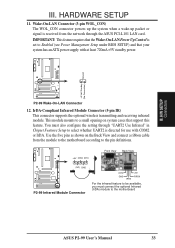
... signal is directed for use with at least 720mA +5V standby power. You must connect the optional Infrared (IrDA) module to the motherboard ASUS P2-99 User's Manual 33 Use the five pins as shown on system cases that your system has an ATX power supply with COM2 or IrDA. ... definitions. +5V IRRX IRTX Front View Back View (NC) GND P2-99 P2-99 Infrared Module Connector IRTX GND IRRX +5V FIRRX For the infrared feature to be available, you must also configure the setting through "UART2 Use Infrared" in Chipset Features Setup to Enabled (see Power Management Setup under BIOS SETUP) ...
... signal is directed for use with at least 720mA +5V standby power. You must connect the optional Infrared (IrDA) module to the motherboard ASUS P2-99 User's Manual 33 Use the five pins as shown on system cases that your system has an ATX power supply with COM2 or IrDA. ... definitions. +5V IRRX IRTX Front View Back View (NC) GND P2-99 P2-99 Infrared Module Connector IRTX GND IRRX +5V FIRRX For the infrared feature to be available, you must also configure the setting through "UART2 Use Infrared" in Chipset Features Setup to Enabled (see Power Management Setup under BIOS SETUP) ...
P2-99 User Manual
Page 48
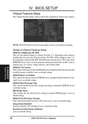
... for items 2-5, depending on default setting. 48 ASUS P2-99 User's Manual DRAM Idle Timer This controls the idle clocks before closing an opened SDRAM page. SDRAM RAS to SDRAM. Leave on default setting. Details of Chipset Features Setup SDRAM Configuration (By SPD) This sets... the optimal timings of the board's chipset. Leave on default setting. Leave on default setting. IV. IV. BIOS SETUP Chipset Features NOTE: SETUP Defaults are using. This 8-...
... for items 2-5, depending on default setting. 48 ASUS P2-99 User's Manual DRAM Idle Timer This controls the idle clocks before closing an opened SDRAM page. SDRAM RAS to SDRAM. Leave on default setting. Details of Chipset Features Setup SDRAM Configuration (By SPD) This sets... the optimal timings of the board's chipset. Leave on default setting. Leave on default setting. IV. IV. BIOS SETUP Chipset Features NOTE: SETUP Defaults are using. This 8-...
P2-99 User Manual
Page 49
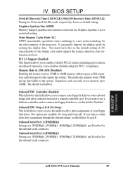
...controller card. Onboard FDC Swap A & B (No Swap) This field allows you to connect your system may not boot. BIOS SETUP Chipset Features ASUS P2-99 User's Manual 49 Memory Hole At 15M-16M (Disabled) Enabling this feature reserves 15MB to 16MB memory address space to ISA expansion cards..., respectively. Expansion cards can only access memory up unavailable to Disabled. If you want to switch drive letter assignments through the onboard chipset, set this field to reverse the hardware drive letter assignments of the processor. It can reside in a Graphics Aperture. BIOS SETUP 16...
...controller card. Onboard FDC Swap A & B (No Swap) This field allows you to connect your system may not boot. BIOS SETUP Chipset Features ASUS P2-99 User's Manual 49 Memory Hole At 15M-16M (Disabled) Enabling this feature reserves 15MB to 16MB memory address space to ISA expansion cards..., respectively. Expansion cards can only access memory up unavailable to Disabled. If you want to switch drive letter assignments through the onboard chipset, set this field to reverse the hardware drive letter assignments of the processor. It can reside in a Graphics Aperture. BIOS SETUP 16...

P2-99 User Manual
Page 50
... to enable the primary IDE channel, secondary IDE channel, both, or disable both a master and a slave making four IDE devices possible. IV. BIOS SETUP Chipset Features 50 ASUS P2-99 User's Manual Onboard PCI IDE Enable (Both) You can select either DMA Channel 1, 3, or Disable. IDE 0 Master/Slave PIO/DMA Mode, IDE 1 Master/Slave...
... to enable the primary IDE channel, secondary IDE channel, both, or disable both a master and a slave making four IDE devices possible. IV. BIOS SETUP Chipset Features 50 ASUS P2-99 User's Manual Onboard PCI IDE Enable (Both) You can select either DMA Channel 1, 3, or Disable. IDE 0 Master/Slave PIO/DMA Mode, IDE 1 Master/Slave...
P2-99 User Manual
Page 58
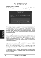
... IDE drives can use another IDE controller that supports four drives, you accepted on the screen. When auto-detection is new and empty. 58 ASUS P2-99 User's Manual If you accept the values, the parameters will appear in the Standard CMOS Setup screen. Choose the line that supports the LBA...two IDE hard disk drives. Remember that if you can only detect one set of parameters for four devices, you are not entered in the Chipset Features Setup screen. IV. Pressing to accept a set of an IDE hard disk drive, and automatically enters them into the Standard CMOS Setup ...
... IDE drives can use another IDE controller that supports four drives, you accepted on the screen. When auto-detection is new and empty. 58 ASUS P2-99 User's Manual If you accept the values, the parameters will appear in the Standard CMOS Setup screen. Choose the line that supports the LBA...two IDE hard disk drives. Remember that if you can only detect one set of parameters for four devices, you are not entered in the Chipset Features Setup screen. IV. Pressing to accept a set of an IDE hard disk drive, and automatically enters them into the Standard CMOS Setup ...

P2-99 User Manual
Page 85
... order to "Other." ASUS P2-99 User's Manual 85 If you are using the ASUS PCI-L101 on an ASUS motherboard, leave the jumper on LAN feature of motherboard, set the jumper to display the LAN data activity. APPENDIX ASUS LAN Card RJ45 LAN Activity Output Signal Intel Chipset Wake on LAN Output Signal ASUS Motherboard type Other...
... order to "Other." ASUS P2-99 User's Manual 85 If you are using the ASUS PCI-L101 on an ASUS motherboard, leave the jumper on LAN feature of motherboard, set the jumper to display the LAN data activity. APPENDIX ASUS LAN Card RJ45 LAN Activity Output Signal Intel Chipset Wake on LAN Output Signal ASUS Motherboard type Other...

