P10sws Asus - P10S WS
P10sws Asus
Related Manual Pages


Similar Questions

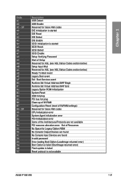
Bios Error Code Dc
Hi, processors and ram are in, bios is updated, and we're getting the error code dC, the board has b...
Hi, processors and ram are in, bios is updated, and we're getting the error code dC, the board has b...
(Posted by amarkiewicz 1 year ago)

Asus P5nt-ws Has Ahci ?
Hi there, Asus P5NT-WS motherboard has AHCI controller ? I have SSD but cant use automatic TRIMM com...
Hi there, Asus P5NT-WS motherboard has AHCI controller ? I have SSD but cant use automatic TRIMM com...
(Posted by brahamstoker 5 years ago)

For Asus P5b
what option can i do if the AGP port of ASus p5b is damaged?
what option can i do if the AGP port of ASus p5b is damaged?
(Posted by felniedormiendo 11 years ago)