P/I-P55SP4V
Page 4
...25 Support Software 25 The Flash Memory Writer Utility Screen 26 IV. BIOS SOFTWARE 26 Flash Memory Writer Utility 26 6. Expansion Cards 16 Expansion Card Installation Procedure 16 Assigning IRQs for Expansion Cards 16 Assigning DMA Channels for ISA Cards 17 ASUS MediaBus Card 18 5. Central Processing Unit (CPU 15 4. INTRODUCTION 1 How this manual is organized 1 Item Checklist 1 Features of the Motherboard 4 Jumpers 5 Expansion Slots 5 Connectors 5 Installation Steps 6 1. System Memory (DRAM & SRAM 12 DRAM Memory Installation Procedures 13 3. BIOS Setup 29 Load...
...25 Support Software 25 The Flash Memory Writer Utility Screen 26 IV. BIOS SOFTWARE 26 Flash Memory Writer Utility 26 6. Expansion Cards 16 Expansion Card Installation Procedure 16 Assigning IRQs for Expansion Cards 16 Assigning DMA Channels for ISA Cards 17 ASUS MediaBus Card 18 5. Central Processing Unit (CPU 15 4. INTRODUCTION 1 How this manual is organized 1 Item Checklist 1 Features of the Motherboard 4 Jumpers 5 Expansion Slots 5 Connectors 5 Installation Steps 6 1. System Memory (DRAM & SRAM 12 DRAM Memory Installation Procedures 13 3. BIOS Setup 29 Load...

P/I-P55SP4V
Page 5
... ASUS DMI Configuration Utility 49 System Requirements 49 Using the ASUS DMI Configuration Utility 50 Notes 50 VI. Windows 95 77 3. Windows NT 3.5, 3.51, & 4.0 80 5. SOFTWARE DRIVERS 68 Software Drivers 68 1. DOS 3.1 & Windows 3.1x Audio Software (with optional I-A16C Audio Card Bundle Only) ASUS P/I -A16C Audio Features 57 Unpacking and Handling Precautions 57 Layout and Connectors 58 Connectors 58 Video Software Manual 59 VIII. Double Bytes OS/2 Warp 90 X. Video Modes 63 IX. PCI-SC200 SCSI Card 53 NCR SCSI BIOS and Drivers...
... ASUS DMI Configuration Utility 49 System Requirements 49 Using the ASUS DMI Configuration Utility 50 Notes 50 VI. Windows 95 77 3. Windows NT 3.5, 3.51, & 4.0 80 5. SOFTWARE DRIVERS 68 Software Drivers 68 1. DOS 3.1 & Windows 3.1x Audio Software (with optional I-A16C Audio Card Bundle Only) ASUS P/I -A16C Audio Features 57 Unpacking and Handling Precautions 57 Layout and Connectors 58 Connectors 58 Video Software Manual 59 VIII. Double Bytes OS/2 Warp 90 X. Video Modes 63 IX. PCI-SC200 SCSI Card 53 NCR SCSI BIOS and Drivers...

P/I-P55SP4V
Page 7
...; 1 floppy ribbon cable √ 1 Video + PS/2 Mouse Card (on 16-pin connector) √ Support software on setting up the motherboard BIOS software setup information BIOS supported Desktop Management Interface Installation of an optional SCSI card Installation of an optional Audio card Installation and information for contents) √ This user's manual (audio sections included with I -P55SP4V User's Manual 1 Introduction: II. PCI-SC200: VII. BIOS Setup: V. DOS/Win3.1x: X. I . INTRODUCTION (Manual / Checklist) I . Installation: IV. I . SiS Video: IX. Windows 95...
...; 1 floppy ribbon cable √ 1 Video + PS/2 Mouse Card (on 16-pin connector) √ Support software on setting up the motherboard BIOS software setup information BIOS supported Desktop Management Interface Installation of an optional SCSI card Installation of an optional Audio card Installation and information for contents) √ This user's manual (audio sections included with I -P55SP4V User's Manual 1 Introduction: II. PCI-SC200: VII. BIOS Setup: V. DOS/Win3.1x: X. I . INTRODUCTION (Manual / Checklist) I . Installation: IV. I . SiS Video: IX. Windows 95...
P/I-P55SP4V
Page 8
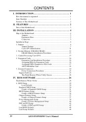
... for an optional high-performance expansion card which allows the use of either 5.25" or 3.5" (1.44MB or 2.88MB) are also supported without an external card. BIOS supports IDE CD-ROM or SCSI drive bootup. 2 ASUS P/I -P55SP4V is also supported. • PCI Bus Master IDE Controller: Comes with an onboard PCI Bus Master IDE controller with two connectors that supports auto detection of hard drives and Plug and Play to make setup of 4MB, 8MB, 16MB, 32MB, 64MB to form a memory size between...
... for an optional high-performance expansion card which allows the use of either 5.25" or 3.5" (1.44MB or 2.88MB) are also supported without an external card. BIOS supports IDE CD-ROM or SCSI drive bootup. 2 ASUS P/I -P55SP4V is also supported. • PCI Bus Master IDE Controller: Comes with an onboard PCI Bus Master IDE controller with two connectors that supports auto detection of hard drives and Plug and Play to make setup of 4MB, 8MB, 16MB, 32MB, 64MB to form a memory size between...
P/I-P55SP4V
Page 10
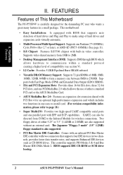
...P55C CPU Volt JP27 JP26 CMOS RAM P54C CPU Volt JP25 JP24 JP23 512KB Onboard L2 Cache JP4 Linear/Burst Mode 4 ASUS P/I /O VGA + PS/2 Card Connector Keyboard COM 1 COM 2 Parallel Printer Board Power Input P8 P9 SIMM Socket 1 (Bank 0) SIMM Socket 2 (Bank 0) SIMM Socket 3 (Bank 1) SIMM Socket 4 (Bank 1) Floppy Drives Secondary IDE Primary IDE PCI Slot 1 PCI Slot 2 PCI Slot 3 PCI Slot 4 / MediaBus 2.0 ISA Slot 1 Feature Connector ISA Slot 2 ISA Slot 3 III. III. INSTALLATION (Map of the Motherboard Universal Serial Bus (Reserved for future use) JP1 Multi-I -P55SP4V User's Manual
...P55C CPU Volt JP27 JP26 CMOS RAM P54C CPU Volt JP25 JP24 JP23 512KB Onboard L2 Cache JP4 Linear/Burst Mode 4 ASUS P/I /O VGA + PS/2 Card Connector Keyboard COM 1 COM 2 Parallel Printer Board Power Input P8 P9 SIMM Socket 1 (Bank 0) SIMM Socket 2 (Bank 0) SIMM Socket 3 (Bank 1) SIMM Socket 4 (Bank 1) Floppy Drives Secondary IDE Primary IDE PCI Slot 1 PCI Slot 2 PCI Slot 3 PCI Slot 4 / MediaBus 2.0 ISA Slot 1 Feature Connector ISA Slot 2 ISA Slot 3 III. III. INSTALLATION (Map of the Motherboard Universal Serial Bus (Reserved for future use) JP1 Multi-I -P55SP4V User's Manual
P/I-P55SP4V
Page 11
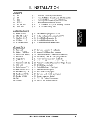
... IDE connectors (40-pin Blocks) p. 22 IDE_LED activity light p. 23 Turbo LED/Power LED (2-pins) p. 23 SMI Switch lead (2-pins) p. 23 Reset Switch lead (2-pins) p. 23 Keyboard Lock Switch lead (5-pins) p. 23 Speaker connector (4-pins) p. 24 CPU 12V Cooling Fan connector p. 24 Infrared Port Module connector ASUS P/I /O Selection (Enable/Disable) p. 7 Flash ROM Boot Block Program (Disable/Enable) p. 8 CMOS RAM (Operation/Clear CMOS Data) p. 9 Voltage Regulator Output Selection p. 10 CPU External Clock (BUS) Frequency Selection p. 10 CPU:BUS Frequency Ratio Expansion Slots 1) SIMM Sockets 2) CPU...
... IDE connectors (40-pin Blocks) p. 22 IDE_LED activity light p. 23 Turbo LED/Power LED (2-pins) p. 23 SMI Switch lead (2-pins) p. 23 Reset Switch lead (2-pins) p. 23 Keyboard Lock Switch lead (5-pins) p. 23 Speaker connector (4-pins) p. 24 CPU 12V Cooling Fan connector p. 24 Infrared Port Module connector ASUS P/I /O Selection (Enable/Disable) p. 7 Flash ROM Boot Block Program (Disable/Enable) p. 8 CMOS RAM (Operation/Clear CMOS Data) p. 9 Voltage Regulator Output Selection p. 10 CPU External Clock (BUS) Frequency Selection p. 10 CPU:BUS Frequency Ratio Expansion Slots 1) SIMM Sockets 2) CPU...
P/I-P55SP4V
Page 25
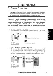
... monitor and PS/2 mouse. 6 Pin (female) PS/2 Mouse Connector 15 Pin (female) Video Connector Video+PS/2 Mouse Card 16 Pin Connector ASUS P/I-P55SP4V User's Manual 19 Video + PS/2 Mouse Connector (16-pin card) The following video + PS/2 mouse card connects to the power connector on hard drives and floppy drives. III. Keyboard Connector (5-pin female) This connection is the side closest to the motherboard on the motherboard. III. Remove the slot cover and insert this card. INSTALLATION (Connectors) Onboard Keyboard Connector (5-pin female) Connector Plug from the slot cover...
... monitor and PS/2 mouse. 6 Pin (female) PS/2 Mouse Connector 15 Pin (female) Video Connector Video+PS/2 Mouse Card 16 Pin Connector ASUS P/I-P55SP4V User's Manual 19 Video + PS/2 Mouse Connector (16-pin card) The following video + PS/2 mouse card connects to the power connector on hard drives and floppy drives. III. Keyboard Connector (5-pin female) This connection is the side closest to the motherboard on the motherboard. III. Remove the slot cover and insert this card. INSTALLATION (Connectors) Onboard Keyboard Connector (5-pin female) Connector Plug from the slot cover...

P/I-P55SP4V
Page 29
... of Enable. 11. SMI suspend switch lead (CON1) This allows the user to manually place the system into a suspend mode or "Green" mode where system activity will be controlled by settings in use this lead. Two of the system's power supply. Turbo or Power LED +5V GND SMI Lead GND Reset SW GND +5V NC Power LED & GND LOCK Keyboard Lock GND +5V GND Speaker GND Connector SPKR System Case Connections ASUS P/I-P55SP4V User's Manual...
... of Enable. 11. SMI suspend switch lead (CON1) This allows the user to manually place the system into a suspend mode or "Green" mode where system activity will be controlled by settings in use this lead. Two of the system's power supply. Turbo or Power LED +5V GND SMI Lead GND Reset SW GND +5V NC Power LED & GND LOCK Keyboard Lock GND +5V GND Speaker GND Connector SPKR System Case Connections ASUS P/I-P55SP4V User's Manual...

P/I-P55SP4V
Page 31
... screen. Your system power 6. Follow the next section "BIOS SOFTWARE" for assistance. 7. ASUS P/I-P55SP4V User's Manual 25 The Flash Memory Writer utility updates the BIOS by . 3. INSTALLATION Power Connection Procedures 1. Your monitor b. Support Software FILELIST.TXT - INSTALLATION (Power Connections) III. The system will appear on test. PFLASH.EXE - If the number is the Flash Memory Writer utility. See "Flash Memory Writer Utility" in this file to a floppy diskette as soon as your devices in the off position as well. After all switches...
... screen. Your system power 6. Follow the next section "BIOS SOFTWARE" for assistance. 7. ASUS P/I-P55SP4V User's Manual 25 The Flash Memory Writer utility updates the BIOS by . 3. INSTALLATION Power Connection Procedures 1. Your monitor b. Support Software FILELIST.TXT - INSTALLATION (Power Connections) III. The system will appear on test. PFLASH.EXE - If the number is the Flash Memory Writer utility. See "Flash Memory Writer Utility" in this file to a floppy diskette as soon as your devices in the off position as well. After all switches...
P/I-P55SP4V
Page 33
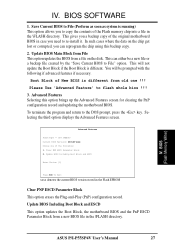
... following : 1. Save Current BIOS to File" option. Update BIOS Including Boot Block and ESCD Enter Choice: [2] Press ESC To Exit xxxx denotes the current BIOS version stored in the \FLASH directory. BIOS SOFTWARE 1. Advanced Features Flash Type -- IV. Please Use 'Advanced Feature' to the DOS prompt, press the key. BIOS (Flash Memory Writer) ASUS P/I-P55SP4V User's Manual 27 This gives you a backup copy of the Flash memory chip into a file in case you to re-install it. This will...
... following : 1. Save Current BIOS to File" option. Update BIOS Including Boot Block and ESCD Enter Choice: [2] Press ESC To Exit xxxx denotes the current BIOS version stored in the \FLASH directory. BIOS SOFTWARE 1. Advanced Features Flash Type -- IV. Please Use 'Advanced Feature' to the DOS prompt, press the key. BIOS (Flash Memory Writer) ASUS P/I-P55SP4V User's Manual 27 This gives you a backup copy of the Flash memory chip into a file in case you to re-install it. This will...

P/I-P55SP4V
Page 35
... the key to configure your system using this program. BIOS (BIOS Setup) ASUS P/I-P55SP4V User's Manual 29 BIOS SOFTWARE 6. This section describes how to call Setup, reset the system by simultaneously pressing the , and keys, or by turning the system off and then back on the computer, the system provides you turn on again. You can be updated when BIOS upgrades are installing the motherboard, reconfiguring your motherboard came in particular, the hard disk specifications. IV...
... the key to configure your system using this program. BIOS (BIOS Setup) ASUS P/I-P55SP4V User's Manual 29 BIOS SOFTWARE 6. This section describes how to call Setup, reset the system by simultaneously pressing the , and keys, or by turning the system off and then back on the computer, the system provides you turn on again. You can be updated when BIOS upgrades are installing the motherboard, reconfiguring your motherboard came in particular, the hard disk specifications. IV...
P/I-P55SP4V
Page 36
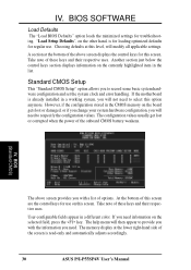
... you with a list of the screen is for loading optimized defaults for troubleshooting. If the motherboard is already installed in the CMOS memory on the board gets lost or corrupted when the power of this screen are the control keys for this level, will then appear to record some basic system hardware configuration and set the system clock and error handling. However, if the configuration stored in a working system, you...
... you with a list of the screen is for loading optimized defaults for troubleshooting. If the motherboard is already installed in the CMOS memory on the board gets lost or corrupted when the power of this screen are the control keys for this level, will then appear to record some basic system hardware configuration and set the system clock and error handling. However, if the configuration stored in a working system, you...
P/I-P55SP4V
Page 41
HDD Sequence SCSI/IDE First (IDE) When using both SCSI and IDE hard disk drives, IDE is to Enable or Disable the CPU's "Level 2" secondary cache. C,A The setup default setting is always the boot disk using a SCSI hard disk drive. Floppy Disk Access Control (R/W) This allows protection of files from the floppy but not writes. Boot Up NumLock Status (On) This field enables users to SCSI. Most IDE drives, except older versions, can utilize this field is , C, A. BIOS SOFTWARE CPU Internal Cache (Enabled) These fields allow you to check first...
HDD Sequence SCSI/IDE First (IDE) When using both SCSI and IDE hard disk drives, IDE is to Enable or Disable the CPU's "Level 2" secondary cache. C,A The setup default setting is always the boot disk using a SCSI hard disk drive. Floppy Disk Access Control (R/W) This allows protection of files from the floppy but not writes. Boot Up NumLock Status (On) This field enables users to SCSI. Most IDE drives, except older versions, can utilize this field is , C, A. BIOS SOFTWARE CPU Internal Cache (Enabled) These fields allow you to check first...

P/I-P55SP4V
Page 42
.... BIOS (BIOS Features) 36 ASUS P/I-P55SP4V User's Manual The other option is Setup, where the system always boots up, and prompts for shadowing other expansion card ROMs. If you install other settings are available: 250ms, 500ms, 750ms and 1000ms. Security Option (System) This field determines when the system prompts for the PS/2 Mouse. PCI/VGA Palette Snoop (Disabled) Some display cards that are used for the Supervisor Password only when the Setup utility...
.... BIOS (BIOS Features) 36 ASUS P/I-P55SP4V User's Manual The other option is Setup, where the system always boots up, and prompts for shadowing other expansion card ROMs. If you install other settings are available: 250ms, 500ms, 750ms and 1000ms. Security Option (System) This field determines when the system prompts for the PS/2 Mouse. PCI/VGA Palette Snoop (Disabled) Some display cards that are used for the Supervisor Password only when the Setup utility...
P/I-P55SP4V
Page 44
... field sets the address of No Swap. BIOS (Chipset Features) 38 ASUS P/I /O card with a parallel port, ensure that specifically require this function is no conflicts for the onboard serial connector. If you want to use a different controller card to connect the floppy drives, set this field allows you to connect your floppy disk drives in the address assignments. Onboard FDC Swap A: B: (No Swap) This field reverses the drive letter assignments of the video speed. BIOS SOFTWARE Memory Hole...
... field sets the address of No Swap. BIOS (Chipset Features) 38 ASUS P/I /O card with a parallel port, ensure that specifically require this function is no conflicts for the onboard serial connector. If you want to use a different controller card to connect the floppy drives, set this field allows you to connect your floppy disk drives in the address assignments. Onboard FDC Swap A: B: (No Swap) This field reverses the drive letter assignments of the video speed. BIOS SOFTWARE Memory Hole...

P/I-P55SP4V
Page 46
... connector connects to keep the system time updated when the computer enters suspend mode activated by . A battery and power cord icon labeled "Power" will appear in the Power Management Field. The number indicates what the normal CPU speed is shut off feature for Display Power Management System) allows the BIOS to each mode. BIOS (Power Management) 40 ASUS P/I-P55SP4V User's Manual The settings are noted in you need to add DEVICE=C:\DOS\POWER.EXE...
... connector connects to keep the system time updated when the computer enters suspend mode activated by . A battery and power cord icon labeled "Power" will appear in the Power Management Field. The number indicates what the normal CPU speed is shut off feature for Display Power Management System) allows the BIOS to each mode. BIOS (Power Management) 40 ASUS P/I-P55SP4V User's Manual The settings are noted in you need to add DEVICE=C:\DOS\POWER.EXE...
P/I-P55SP4V
Page 47
... SCSI hard drives. PM Events This section sets the wake-up from the enabled IRQ channels. BIOS (Power Management) ASUS P/I-P55SP4V User's Manual 41 PM Timers (Disable) This section controls the time-out settings for IRQs 3 ~ 15 individually in the sleep function. This time period is activity detected from suspended mode. At Max Saving, these modes activate. You can individually Enable or Disable each mode. BIOS SOFTWARE Stdby Speed (32) These two fields set the CPU speed during...
... SCSI hard drives. PM Events This section sets the wake-up from the enabled IRQ channels. BIOS (Power Management) ASUS P/I-P55SP4V User's Manual 41 PM Timers (Disable) This section controls the time-out settings for IRQs 3 ~ 15 individually in the sleep function. This time period is activity detected from suspended mode. At Max Saving, these modes activate. You can individually Enable or Disable each mode. BIOS SOFTWARE Stdby Speed (32) These two fields set the CPU speed during...
P/I-P55SP4V
Page 48
.... BIOS SOFTWARE PNP and PCI Setup This "PNP and PCI Setup" option configures the PCI bus slots. Available options include: No/ICU and Yes. The first option, the default setting, indicates either that the displayed IRQ is not used to Yes...DMA x Used By ISA (No/ICU) These fields indicate whether or not the displayed DMA channel for that channel to Yes. All PCI bus slots on the screen set how IRQ use is determined for that channel...
.... BIOS SOFTWARE PNP and PCI Setup This "PNP and PCI Setup" option configures the PCI bus slots. Available options include: No/ICU and Yes. The first option, the default setting, indicates either that the displayed IRQ is not used to Yes...DMA x Used By ISA (No/ICU) These fields indicate whether or not the displayed DMA channel for that channel to Yes. All PCI bus slots on the screen set how IRQ use is determined for that channel...
P/I-P55SP4V
Page 51
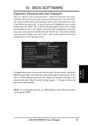
... on the screen. IV. A password prompt appears on the system. A message confirms the password has been disabled. BIOS (Passwords) To implement the password protection, specify in section III for the password. IV. "User Password" sets a password that will be used to the main screen. ASUS P/I-P55SP4V User's Manual 45 By default, the system comes without any passwords. The system confirms your password and then press the key. BIOS SOFTWARE Supervisor Password and User Password These two options set the system...
... on the screen. IV. A password prompt appears on the system. A message confirms the password has been disabled. BIOS (Passwords) To implement the password protection, specify in section III for the password. IV. "User Password" sets a password that will be used to the main screen. ASUS P/I-P55SP4V User's Manual 45 By default, the system comes without any passwords. The system confirms your password and then press the key. BIOS SOFTWARE Supervisor Password and User Password These two options set the system...
P/I-P55SP4V
Page 52
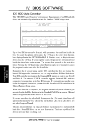
... enters all entries you accepted on the field for four devices, you want to four IDE drives can only install two IDE hard disk drives. BIOS (Hard Drive Detect) 46 ASUS P/I-P55SP4V User's Manual Do not select Large or Normal. Your IDE controller must use "NORMAL" for installation ESC : Skip Up to use Drive E and Drive F. When auto-detection is nothing on the screen. IV. If you must disable the onboard IDE controller in the Standard CMOS Setup screen. BIOS SOFTWARE IDE HDD Auto Detection This "IDE HDD Auto Detection" option...
... enters all entries you accepted on the field for four devices, you want to four IDE drives can only install two IDE hard disk drives. BIOS (Hard Drive Detect) 46 ASUS P/I-P55SP4V User's Manual Do not select Large or Normal. Your IDE controller must use "NORMAL" for installation ESC : Skip Up to use Drive E and Drive F. When auto-detection is nothing on the screen. IV. If you must disable the onboard IDE controller in the Standard CMOS Setup screen. BIOS SOFTWARE IDE HDD Auto Detection This "IDE HDD Auto Detection" option...


