
NR-LSR User Manual
Page 8
...and connectors on the motherboard. • Chapter 3: Powering up This chapter describes the power up sequence and gives information on the ASUS NR-LSR motherboard. How this guide This user guide contains detailed information on the BIOS beep codes. • Chapter 4: BIOS setup This ...this guide is organized This manual contains the following parts: • Chapter 1: Product introduction This chapter describes the features of the NR-LSR motherboard. Detailed descriptions of the motherboard and the new technology it supports. • Chapter 2: Hardware information This chapter lists the...
...and connectors on the motherboard. • Chapter 3: Powering up This chapter describes the power up sequence and gives information on the ASUS NR-LSR motherboard. How this guide This user guide contains detailed information on the BIOS beep codes. • Chapter 4: BIOS setup This ...this guide is organized This manual contains the following parts: • Chapter 1: Product introduction This chapter describes the features of the NR-LSR motherboard. Detailed descriptions of the motherboard and the new technology it supports. • Chapter 2: Hardware information This chapter lists the...

NR-LSR User Manual
Page 14
Chapter summary 1.1 Welcome 1-1 1.2 Special features 1-2 1.3 Motherboard overview 1-6 ASUS NR-LSR motherboard
Chapter summary 1.1 Welcome 1-1 1.2 Special features 1-2 1.3 Motherboard overview 1-6 ASUS NR-LSR motherboard

NR-LSR User Manual
Page 15
... pre-installed in the 1U system. The figure below shows the top view of the NR-LSR motherboard installed in the ASUS AP160R-S 1U barebone server system. ASUS NR-LSR motherboard user guide 1-1 The NR-LSR supports the Intel® Pentium® 4 processor in the long line of new features and latest technologies making it another standout in...
... pre-installed in the 1U system. The figure below shows the top view of the NR-LSR motherboard installed in the ASUS AP160R-S 1U barebone server system. ASUS NR-LSR motherboard user guide 1-1 The NR-LSR supports the Intel® Pentium® 4 processor in the long line of new features and latest technologies making it another standout in...

NR-LSR User Manual
Page 17
ASUS NR-LSR motherboard user guide 1-3 The IDE connectors support Ultra DMA 100/66/33, PIO modes 3 & 4 devices. Integrated IDE bridge The motherboard includes two connectors to provide onboard video solution. Onboard VGA The ATI Rage-XL PCI-based VGA controller integrates an 8MB display SDRAM to support an IDE board with dual-channel bus master IDE connectors.
ASUS NR-LSR motherboard user guide 1-3 The IDE connectors support Ultra DMA 100/66/33, PIO modes 3 & 4 devices. Integrated IDE bridge The motherboard includes two connectors to provide onboard video solution. Onboard VGA The ATI Rage-XL PCI-based VGA controller integrates an 8MB display SDRAM to support an IDE board with dual-channel bus master IDE connectors.

NR-LSR User Manual
Page 19
ASUS NR-LSR motherboard user guide 1-5 A chassis intrusion event is retained in sleep mode. The BIOS has a boot block write protection and HD/SCSI/MO/ZIP/CD/Floppy ... hardware levels of the motherboard meet the stringent requirements for Windows NT/2000/XP. Chassis intrusion detection The motherboard supports chassis intrusion monitoring through the ASUS ASIC. The new SDG 2.0 requirements for systems and components are based on the following high-level goals: support for Plug-and-Play compatibility and power...
ASUS NR-LSR motherboard user guide 1-5 A chassis intrusion event is retained in sleep mode. The BIOS has a boot block write protection and HD/SCSI/MO/ZIP/CD/Floppy ... hardware levels of the motherboard meet the stringent requirements for Windows NT/2000/XP. Chassis intrusion detection The motherboard supports chassis intrusion monitoring through the ASUS ASIC. The new SDG 2.0 requirements for systems and components are based on the following high-level goals: support for Plug-and-Play compatibility and power...

NR-LSR User Manual
Page 21
1 23 4 56 7 89 20 19 18 17 16 15 14 13 12 11 10 21 22 23 24 25 26 27 28 29 30 31 32 ASUS NR-LSR motherboard user guide 1-7
1 23 4 56 7 89 20 19 18 17 16 15 14 13 12 11 10 21 22 23 24 25 26 27 28 29 30 31 32 ASUS NR-LSR motherboard user guide 1-7

NR-LSR User Manual
Page 23
...; Pentium® 4 processor with EPP and ECP capabilities, a floppy drive, and PS/2 keyboard and mouse. 16 ASUS ASIC. These connectors are for the optional ASUS Server Management daughterboard. 15 LPC super I /O functionality. The LSI 53C1010R SCSI controller supports up to select the CPU ...port with 400 MHz system bus that include hardware and system voltage monitoring, IRQ routing, among others. 17 LSI® SCSI controller. ASUS NR-LSR motherboard user guide 1-9 This 8-switch Dual Inline Package (DIP) allows you to 30 SCSI devices, and data transfers of 160Mbps. ...
...; Pentium® 4 processor with EPP and ECP capabilities, a floppy drive, and PS/2 keyboard and mouse. 16 ASUS ASIC. These connectors are for the optional ASUS Server Management daughterboard. 15 LPC super I /O functionality. The LSI 53C1010R SCSI controller supports up to select the CPU ...port with 400 MHz system bus that include hardware and system voltage monitoring, IRQ routing, among others. 17 LSI® SCSI controller. ASUS NR-LSR motherboard user guide 1-9 This 8-switch Dual Inline Package (DIP) allows you to 30 SCSI devices, and data transfers of 160Mbps. ...

NR-LSR User Manual
Page 26
Chapter summary 2.1 Motherboard installation 2-1 2.2 Motherboard layout 2-2 2.3 Before you proceed 2-3 2.4 Central Processing Unit (CPU 2-4 2.5 System memory 2-8 2.6 Expansion slots 2-11 2.7 Switches 2-13 2.8 Connectors 2-15 ASUS NR-LSR motherboard
Chapter summary 2.1 Motherboard installation 2-1 2.2 Motherboard layout 2-2 2.3 Before you proceed 2-3 2.4 Central Processing Unit (CPU 2-4 2.5 System memory 2-8 2.6 Expansion slots 2-11 2.7 Switches 2-13 2.8 Connectors 2-15 ASUS NR-LSR motherboard

NR-LSR User Manual
Page 27
Do not overtighten the screws! The NR-LSR uses the extended ATX form factor that you place it . Make sure to do so may damage the motherboard. The edge with external ports goes .... 2.1.1 Placement direction When installing the motherboard, make sure that measures 12 x 12 inches (30.5 x 30.5 cm). Place this side towards the rear of the chassis ASUS NR-LSR motherboard user guide 2-1 Failure to unplug the power cord before installing or removing the motherboard.
Do not overtighten the screws! The NR-LSR uses the extended ATX form factor that you place it . Make sure to do so may damage the motherboard. The edge with external ports goes .... 2.1.1 Placement direction When installing the motherboard, make sure that measures 12 x 12 inches (30.5 x 30.5 cm). Place this side towards the rear of the chassis ASUS NR-LSR motherboard user guide 2-1 Failure to unplug the power cord before installing or removing the motherboard.

NR-LSR User Manual
Page 29
... that the ATX power supply is switched off or the power cord is detached from the wall socket before handling components to avoid damaging them . 4. ASUS NR-LSR motherboard user guide 2-3 Whenever you install motherboard components or change any motherboard settings. 1. 2.3 Before you proceed Take note of the following precautions before you uninstall...
... that the ATX power supply is switched off or the power cord is detached from the wall socket before handling components to avoid damaging them . 4. ASUS NR-LSR motherboard user guide 2-3 Whenever you install motherboard components or change any motherboard settings. 1. 2.3 Before you proceed Take note of the following precautions before you uninstall...

NR-LSR User Manual
Page 31
2.4.2 Installing the CPU Follow these steps to 90°-100° angle, otherwise the CPU does not fit in completely. Socket Lever 90 - 100 Make sure that the socket lever is lifted up to a 90°-100° angle. ASUS NR-LSR motherboard user guide 2-5 Unlock the socket by pressing the lever sideways, then lift it up to install a CPU. 1. Locate the 478-pin ZIF socket on the motherboard. 2.
2.4.2 Installing the CPU Follow these steps to 90°-100° angle, otherwise the CPU does not fit in completely. Socket Lever 90 - 100 Make sure that the socket lever is lifted up to a 90°-100° angle. ASUS NR-LSR motherboard user guide 2-5 Unlock the socket by pressing the lever sideways, then lift it up to install a CPU. 1. Locate the 478-pin ZIF socket on the motherboard. 2.

NR-LSR User Manual
Page 33
Hold down the heatsink lightly and twist each of the heatsink placement as shown (ASUS logo facing the rear panel). 2. Take note of the four screws with a flat screw driver just enough to attach the heatsink to the motherboard. 3. When the four screws are attached, tighten them one by one orientation. The heatsink fits in only one to install the CPU heatsink. 1. 2.4.3 Installing the heatsink Follow these steps to completely secure the heatsink. ASUS NR-LSR motherboard user guide 2-7 Carefully place the heatsink on top of the installed CPU.
Hold down the heatsink lightly and twist each of the heatsink placement as shown (ASUS logo facing the rear panel). 2. Take note of the four screws with a flat screw driver just enough to attach the heatsink to the motherboard. 3. When the four screws are attached, tighten them one by one orientation. The heatsink fits in only one to install the CPU heatsink. 1. 2.4.3 Installing the heatsink Follow these steps to completely secure the heatsink. ASUS NR-LSR motherboard user guide 2-7 Carefully place the heatsink on top of the installed CPU.

NR-LSR User Manual
Page 35
.../1600 registered ECC DIMMs. Make sure to pair DDRA2/DDRB2. The same rule applies to use only the specified DIMM types for stable system operation. ASUS NR-LSR motherboard user guide 2-9 An exception to the above rule allows you can install. For example, if you installed a 512MB module into DDRA1, you install identical...
.../1600 registered ECC DIMMs. Make sure to pair DDRA2/DDRB2. The same rule applies to use only the specified DIMM types for stable system operation. ASUS NR-LSR motherboard user guide 2-9 An exception to the above rule allows you can install. For example, if you installed a 512MB module into DDRA1, you install identical...
NR-LSR User Manual
Page 37
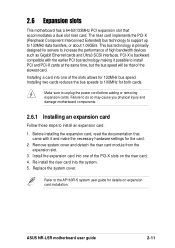
Before installing the expansion card, read the documentation that accommodates a dual slot riser card. ASUS NR-LSR motherboard user guide 2-11 Installing a card into one of the slots allows for 133MHz bus speed. Make sure to 133MHz data transfers, or about 1.06GB/s. ...
Before installing the expansion card, read the documentation that accommodates a dual slot riser card. ASUS NR-LSR motherboard user guide 2-11 Installing a card into one of the slots allows for 133MHz bus speed. Make sure to 133MHz data transfers, or about 1.06GB/s. ...

NR-LSR User Manual
Page 39
... CLKSW ON 12345 ON 12345 ON 12345 CPU 100MHz 101MHz 103MHz ON 12345 ON 12345 ® NR-LSR NR-LSR CPU External Frequency Selection CPU 105MHz 110MHz ASUS NR-LSR motherboard user guide 2-13 Keep the default settings for stable system operation. To select the CPU ...The following figure shows the location and default settings of the CPU's external frequency (or Bus Clock). OFF ON OFF ON ® NR-LSR NR-LSR DIP Switches ON 12345678 ON 12345 CLKSW U78 1.Frequency Selection 2.Frequency Selection 3.Frequency Selection 4.Frequency Selection 5.Spread Spectrum 1.Reserved 2.Reserved ...
... CLKSW ON 12345 ON 12345 ON 12345 CPU 100MHz 101MHz 103MHz ON 12345 ON 12345 ® NR-LSR NR-LSR CPU External Frequency Selection CPU 105MHz 110MHz ASUS NR-LSR motherboard user guide 2-13 Keep the default settings for stable system operation. To select the CPU ...The following figure shows the location and default settings of the CPU's external frequency (or Bus Clock). OFF ON OFF ON ® NR-LSR NR-LSR DIP Switches ON 12345678 ON 12345 CLKSW U78 1.Frequency Selection 2.Frequency Selection 3.Frequency Selection 4.Frequency Selection 5.Spread Spectrum 1.Reserved 2.Reserved ...

NR-LSR User Manual
Page 41
... into a slot opening at the back of the system chassis. U79 +5Volt (Power Supply Stand By) Chassis Signal Ground ® NR-LSR NR-LSR Chassis Open Alarm Lead 2. COM2 1 ® NR-LSR NR-LSR Serial COM2 Connector ASUS NR-LSR motherboard user guide 2-15 2.8 Connectors This section describes and illustrates the internal connectors on the motherboard. 1. When you wish to record...
... into a slot opening at the back of the system chassis. U79 +5Volt (Power Supply Stand By) Chassis Signal Ground ® NR-LSR NR-LSR Chassis Open Alarm Lead 2. COM2 1 ® NR-LSR NR-LSR Serial COM2 Connector ASUS NR-LSR motherboard user guide 2-15 2.8 Connectors This section describes and illustrates the internal connectors on the motherboard. 1. When you wish to record...

NR-LSR User Manual
Page 43
... cable matches the ground pin of the connector. FAN2 Rotation FAN4 +12V GND FAN3 ® NR-LSR NR-LSR 12-Volt Cooling Fan Power GND +12V Rotation SYSFAN1 SYSFAN2 Rotation Rotation +12V GND Rotation Rotation +12V GND 1 ® NR-LSR 1 NR-LSR 8-Pin SystemFan ASUS NR-LSR motherboard user guide 2-17 CPU, Chassis, and Power Fan Connectors (3-pin FAN1, FAN2, FAN3...
... cable matches the ground pin of the connector. FAN2 Rotation FAN4 +12V GND FAN3 ® NR-LSR NR-LSR 12-Volt Cooling Fan Power GND +12V Rotation SYSFAN1 SYSFAN2 Rotation Rotation +12V GND Rotation Rotation +12V GND 1 ® NR-LSR 1 NR-LSR 8-Pin SystemFan ASUS NR-LSR motherboard user guide 2-17 CPU, Chassis, and Power Fan Connectors (3-pin FAN1, FAN2, FAN3...

NR-LSR User Manual
Page 45
Connect to BPCON connectors on the backplane board ® NR-LSR NR-LSR BPCON Connectors 7. If the motherboard is not installed in the AP160R-S system, you to turn the power ON or OFF, or reset the system. Power ... motherboard to BPCON connectors on the motherboard Connect to the backplane board. 6. Backplane bridge connectors (BPCON) These connectors are accessible from the front panel. ® NR-LSR NR-LSR POWER Setting PWRBTN 12 23 POWER ON RESET ASUS NR-LSR motherboard user guide 2-19
Connect to BPCON connectors on the backplane board ® NR-LSR NR-LSR BPCON Connectors 7. If the motherboard is not installed in the AP160R-S system, you to turn the power ON or OFF, or reset the system. Power ... motherboard to BPCON connectors on the motherboard Connect to the backplane board. 6. Backplane bridge connectors (BPCON) These connectors are accessible from the front panel. ® NR-LSR NR-LSR POWER Setting PWRBTN 12 23 POWER ON RESET ASUS NR-LSR motherboard user guide 2-19

NR-LSR User Manual
Page 48
Chapter summary 3.1 Starting up for the first time 3-1 3.2 Powering off the computer 3-2 ASUS NR-LSR motherboard
Chapter summary 3.1 Starting up for the first time 3-1 3.2 Powering off the computer 3-2 ASUS NR-LSR motherboard

NR-LSR User Manual
Page 49
... power, the power LED on the system front panel case lights up or switch between orange and green after the system LED turns on tests. ASUS NR-LSR motherboard user guide 3-1 Connect the power cord to the power connector at a lower frequency 7. External SCSI devices (starting with the last device on test. Be...
... power, the power LED on the system front panel case lights up or switch between orange and green after the system LED turns on tests. ASUS NR-LSR motherboard user guide 3-1 Connect the power cord to the power connector at a lower frequency 7. External SCSI devices (starting with the last device on test. Be...


