NCT-D MB User Manual English Version
Page 7
... the product, contact a qualified service technician or your dealer immediately. • To avoid short circuits, keep paper clips, screws, and staples away from connectors, slots, sockets and circuitry. • Avoid dust, humidity, and temperature extremes. vii If you are not sure about the voltage of the electrical outlet you add a device...
... the product, contact a qualified service technician or your dealer immediately. • To avoid short circuits, keep paper clips, screws, and staples away from connectors, slots, sockets and circuitry. • Avoid dust, humidity, and temperature extremes. vii If you are not sure about the voltage of the electrical outlet you add a device...
NCT-D MB User Manual English Version
Page 10
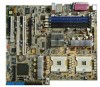
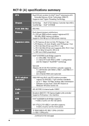
NCT-D (A) specifications summary CPU Chipset Front Side Bus Memory Expansion slots Storage Wi-Fi solution (optional) Audio LAN USB IEEE 1394 Dual 604-pin sockets for IEEE 802.11g/b wireless standards - up to 8 GB system memory 1 x PCI Express x8 slot (x4 link, PCI Express 1.0a) 1 x PCI Express ...slot (PCI-X 1.0a) 1 x PCI-X 66 MHz/64-bit slot (supports ZCR, PCI-X 1.0a) 1 x PCI 33 MHz/32-bit/5V (PCI 2.3) 1 x WiFi slot (ASUS proprietary) Intel® 6300ESB South Bridge supports: - 2 x Ultra DMA 100/66/33 - 2 x Serial ATA with RAID 0, RAID 1 configuration and the Adaptec® HostRAID™ ...
NCT-D (A) specifications summary CPU Chipset Front Side Bus Memory Expansion slots Storage Wi-Fi solution (optional) Audio LAN USB IEEE 1394 Dual 604-pin sockets for IEEE 802.11g/b wireless standards - up to 8 GB system memory 1 x PCI Express x8 slot (x4 link, PCI Express 1.0a) 1 x PCI Express ...slot (PCI-X 1.0a) 1 x PCI-X 66 MHz/64-bit slot (supports ZCR, PCI-X 1.0a) 1 x PCI 33 MHz/32-bit/5V (PCI 2.3) 1 x WiFi slot (ASUS proprietary) Intel® 6300ESB South Bridge supports: - 2 x Ultra DMA 100/66/33 - 2 x Serial ATA with RAID 0, RAID 1 configuration and the Adaptec® HostRAID™ ...
NCT-D MB User Manual English Version
Page 16
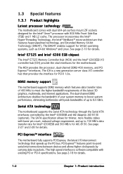
...® 6300ESB and 300 MB/s for AIC-8130. 1.3 Special features 1.3.1 Product highlights Latest processor technology The motherboard comes with dual 604-pin surface mount ZIF sockets designed for the Intel® Xeon™ processor with existing PCI or PCI-X specifications. The processor incorporates the Intel® Hyper-Threading Technology, the Intel...
...® 6300ESB and 300 MB/s for AIC-8130. 1.3 Special features 1.3.1 Product highlights Latest processor technology The motherboard comes with dual 604-pin surface mount ZIF sockets designed for the Intel® Xeon™ processor with existing PCI or PCI-X specifications. The processor incorporates the Intel® Hyper-Threading Technology, the Intel...
NCT-D MB User Manual English Version
Page 23
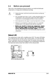
... shows the location of the following precautions before you install motherboard components or change any motherboard settings. • Unplug the power cord from the wall socket before removing or plugging in soft-off or the power c o r d i s d e t a c h e d f r o m t h e p o w e r s u p p l y . Failure to do so may cause severe damage to avoid touching ... with the component. • Before you should shut down the system and unplug the power cable before touching any motherboard component. SB_PWR1 NCT-D NCT-D Standby power LED ON Standby Power OFF Powered Off ASUS NCT-D 2-1
... shows the location of the following precautions before you install motherboard components or change any motherboard settings. • Unplug the power cord from the wall socket before removing or plugging in soft-off or the power c o r d i s d e t a c h e d f r o m t h e p o w e r s u p p l y . Failure to do so may cause severe damage to avoid touching ... with the component. • Before you should shut down the system and unplug the power cable before touching any motherboard component. SB_PWR1 NCT-D NCT-D Standby power LED ON Standby Power OFF Powered Off ASUS NCT-D 2-1
NCT-D MB User Manual English Version
Page 28
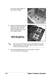
Heatsink hole matched to section "2.2.2 Screw holes" for illustration. 2-6 Chapter 2: Hardware information otherwise, you can not install the CPU heatsinks properly. 11. Install the motherboard with 10 screws. Secure the motherboard with the external I/O ports toward the chassis rear panel. The CPU sockets should be right on the support plates; The support plates appear as shown when installed. 10. Refer to a nut on the support plate Make sure that the CPU heatsink holes on the motherboard perfectly match the metal nuts on top of the support plates.
Heatsink hole matched to section "2.2.2 Screw holes" for illustration. 2-6 Chapter 2: Hardware information otherwise, you can not install the CPU heatsinks properly. 11. Install the motherboard with 10 screws. Secure the motherboard with the external I/O ports toward the chassis rear panel. The CPU sockets should be right on the support plates; The support plates appear as shown when installed. 10. Refer to a nut on the support plate Make sure that the CPU heatsink holes on the motherboard perfectly match the metal nuts on top of the support plates.
NCT-D MB User Manual English Version
Page 30
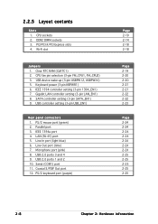
CPU sockets 2. IEEE 1394 controller setting (3-pin 1394_EN1) 7. USB 2.0 ports 3 and 4 9. 2.2.5 Layout contents Slots 1. PCI/PCI-X/PCI Express slots 4. USB device wake-up (3-pin USBPW12, USBPW34) 5. PS/2 ... S/PDIF Out port 12. Gigabit LAN controller setting (3-pin LAN_EN1) 8. SATA controller setting (3-pin SATA_EN1) 9. Line Out port (lime) 7. Serial (COM1) port 11. DDR2 DIMM sockets 3. Keyboard power (3-pin KBPWR1) 6. Wi-Fi slot Jumpers 1. CPU fan pin selection (3-pin FM_CPU1, FM_CPU2) 3. Clear RTC RAM (CLRTC1) 2. USB controller setting (3-pin USB_EN1) Rear...
CPU sockets 2. IEEE 1394 controller setting (3-pin 1394_EN1) 7. USB 2.0 ports 3 and 4 9. 2.2.5 Layout contents Slots 1. PCI/PCI-X/PCI Express slots 4. USB device wake-up (3-pin USBPW12, USBPW34) 5. PS/2 ... S/PDIF Out port 12. Gigabit LAN controller setting (3-pin LAN_EN1) 8. SATA controller setting (3-pin SATA_EN1) 9. Line Out port (lime) 7. Serial (COM1) port 11. DDR2 DIMM sockets 3. Keyboard power (3-pin KBPWR1) 6. Wi-Fi slot Jumpers 1. CPU fan pin selection (3-pin FM_CPU1, FM_CPU2) 3. Clear RTC RAM (CLRTC1) 2. USB controller setting (3-pin USB_EN1) Rear...
NCT-D MB User Manual English Version
Page 32
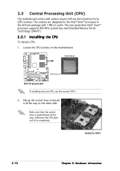
... processor supports 800 MHz system bus and Extended Memory 64-bit Technology (EM64T). 2.3.1 Installling the CPU To install a CPU: 1. Flip up the socket lever and push it all the way, otherwise the CPU does not fit in the 604-pin package with surface mount 604-pin Zero Insertion... in completely. Make sure that the socket lever is pushed back all the way to the other side. 2.3 Central Processing Unit (CPU) The motherboard comes with 1 MB L2 cache. Intel Xeon Gold Arrow NCT-D NCT-D Socket 604 If installing only one CPU, use the socket CPU1. 2. Locate the CPU sockets on the motherboard.
... processor supports 800 MHz system bus and Extended Memory 64-bit Technology (EM64T). 2.3.1 Installling the CPU To install a CPU: 1. Flip up the socket lever and push it all the way, otherwise the CPU does not fit in the 604-pin package with surface mount 604-pin Zero Insertion... in completely. Make sure that the socket lever is pushed back all the way to the other side. 2.3 Central Processing Unit (CPU) The motherboard comes with 1 MB L2 cache. Intel Xeon Gold Arrow NCT-D NCT-D Socket 604 If installing only one CPU, use the socket CPU1. 2. Locate the CPU sockets on the motherboard.
NCT-D MB User Manual English Version
Page 33
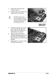
Carefully insert the CPU into the socket to prevent bending the pins and damaging the CPU! 5. DO NOT force the CPU into the socket until it is locked. 6. Apply the thermal interface material (thermal grease) to install a second CPU. Repeat steps 1 to 6 if you wish to the top ...of the CPU. Carefully push down the socket lever to indicate that it fits in one correct orientation. The lever clicks on the side tab to secure the CPU. 3. Position the CPU above the socket as shown. 4. Marked corner (gold arrow) ASUS NCT-D 2-11 The CPU fits only in place. This ...
Carefully insert the CPU into the socket to prevent bending the pins and damaging the CPU! 5. DO NOT force the CPU into the socket until it is locked. 6. Apply the thermal interface material (thermal grease) to install a second CPU. Repeat steps 1 to 6 if you wish to the top ...of the CPU. Carefully push down the socket lever to indicate that it fits in one correct orientation. The lever clicks on the side tab to secure the CPU. 3. Position the CPU above the socket as shown. 4. Marked corner (gold arrow) ASUS NCT-D 2-11 The CPU fits only in place. This ...
NCT-D MB User Manual English Version
Page 36
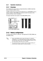
... modules from the same vendor. Refer to match the break on the ASUS website (www.asus.com) for details. • This motherboard does not support memory modules made up of the DDR2 DIMM sockets: NCT-D NCT-D DDR2 DIMM sockets 2.4.2 Memory configurations You may install 256 MB, 512 MB and 1... GB registered ECC DDR2 DIMMs into the DIMM sockets. • Always install DIMMs with four ...
... modules from the same vendor. Refer to match the break on the ASUS website (www.asus.com) for details. • This motherboard does not support memory modules made up of the DDR2 DIMM sockets: NCT-D NCT-D DDR2 DIMM sockets 2.4.2 Memory configurations You may install 256 MB, 512 MB and 1... GB registered ECC DDR2 DIMMs into the DIMM sockets. • Always install DIMMs with four ...
NCT-D MB User Manual English Version
Page 37
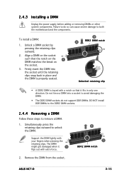
...back in only one direction. Simultaneously press the retaining clips outward to both the motherboard and the components. Remove the DIMM from the socket. 2 1 DDR2 DIMM notch ASUS NCT-D 2-15 To install a DIMM: 1. The DIMM might get damaged when it fits in place and the DIMM is properly seated... fingers when pressing the retaining clips. Failure to do not support DDR DIMMs. DO NOT install DDR DIMMs to the DDR2 DIMM sockets. 2.4.4 Removing a DIMM Follow these steps to remove a DIMM. 1. 2.4.3 Installing a DIMM Unplug the power supply before adding or removing ...
...back in only one direction. Simultaneously press the retaining clips outward to both the motherboard and the components. Remove the DIMM from the socket. 2 1 DDR2 DIMM notch ASUS NCT-D 2-15 To install a DIMM: 1. The DIMM might get damaged when it fits in place and the DIMM is properly seated... fingers when pressing the retaining clips. Failure to do not support DDR DIMMs. DO NOT install DDR DIMMs to the DDR2 DIMM sockets. 2.4.4 Removing a DIMM Follow these steps to remove a DIMM. 1. 2.4.3 Installing a DIMM Unplug the power supply before adding or removing ...
NCT-D MB User Manual English Version
Page 63
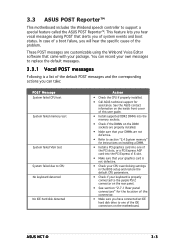
...default messages. 3.3.1 Vocal POST messages Following is properly connected to support a special feature called the ASUS POST Reporter™. ASUS NCT-D 3-3 3.3 ASUS POST Reporter™ This motherboard includes the Winbond speech controller to the purple PS/2 connector on ...installing a DIMM. • Install a PCI graphics card into one of the PCI slots, or a PCI Express AGP card into the memory sockets. • Check if the DIMMs on the DIMM sockets...
...default messages. 3.3.1 Vocal POST messages Following is properly connected to support a special feature called the ASUS POST Reporter™. ASUS NCT-D 3-3 3.3 ASUS POST Reporter™ This motherboard includes the Winbond speech controller to the purple PS/2 connector on ...installing a DIMM. • Install a PCI graphics card into one of the PCI slots, or a PCI Express AGP card into the memory sockets. • Check if the DIMMs on the DIMM sockets...


