User Guide
Page 1
Motherboard NCL-DS Series NCL-DS NCL-D NCL-DR1
Motherboard NCL-DS Series NCL-DS NCL-D NCL-DR1
User Guide
Page 3
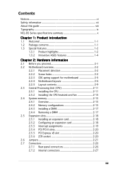
... vi Safety information vii About this guide viii Typography ix NCL-DS Series specifications summary x Chapter 1: Product introduction 1.1 Welcome 1-1 1.2 Package contents 1-1 1.3 Special features 1-2 1.3.1 Product highlights 1-2 1.3.2 Innovative ASUS features 1-4 Chapter 2: Hardware information 2.1 Before you proceed 2-1 2.2 Motherboard overview 2-2 2.2.1 Placement direction 2-2 2.2.2 Screw holes 2-2 2.2.3 CEK spring support for motherboard 2-3 2.2.4 Motherboard layouts 2-6 2.2.5 Layout contents 2-9 2.3 Central Processing Unit (CPU 2-11 2.3.1 Installling...
... vi Safety information vii About this guide viii Typography ix NCL-DS Series specifications summary x Chapter 1: Product introduction 1.1 Welcome 1-1 1.2 Package contents 1-1 1.3 Special features 1-2 1.3.1 Product highlights 1-2 1.3.2 Innovative ASUS features 1-4 Chapter 2: Hardware information 2.1 Before you proceed 2-1 2.2 Motherboard overview 2-2 2.2.1 Placement direction 2-2 2.2.2 Screw holes 2-2 2.2.3 CEK spring support for motherboard 2-3 2.2.4 Motherboard layouts 2-6 2.2.5 Layout contents 2-9 2.3 Central Processing Unit (CPU 2-11 2.3.1 Installling...
User Guide
Page 7
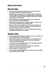
... extremes. If you detect any area where it by yourself. Do not place the product in your retailer. Operation safety • Before installing the motherboard and adding devices on a stable surface. • If you add a device. • Before connecting or removing signal cables from the... motherboard, ensure that all power cables are unplugged. • Seek professional assistance before the signal cables are not damaged. If you are not sure about ...
... extremes. If you detect any area where it by yourself. Do not place the product in your retailer. Operation safety • Before installing the motherboard and adding devices on a stable surface. • If you add a device. • Before connecting or removing signal cables from the... motherboard, ensure that all power cables are unplugged. • Seek professional assistance before the signal cables are not damaged. If you are not sure about ...
User Guide
Page 8
...; Chapter 4: BIOS setup This chapter tells how to when configuring the motherboard. Refer to perform when installing system components. Optional documentation Your product package may have to the ASUS contact information. 2. How this guide This user guide contains the information ...additional information and for product and software updates. 1. ASUS websites The ASUS website provides updated information on the motherboard. • Chapter 3: Powering up This chapter describes the power up sequence and ways of the motherboard and the new technologies it supports. • Chapter...
...; Chapter 4: BIOS setup This chapter tells how to when configuring the motherboard. Refer to perform when installing system components. Optional documentation Your product package may have to the ASUS contact information. 2. How this guide This user guide contains the information ...additional information and for product and software updates. 1. ASUS websites The ASUS website provides updated information on the motherboard. • Chapter 3: Powering up This chapter describes the power up sequence and ways of the motherboard and the new technologies it supports. • Chapter...
User Guide
Page 13
This chapter describes the motherboard features and the new technologies it supports. 1Product introduction
This chapter describes the motherboard features and the new technologies it supports. 1Product introduction

User Guide
Page 15
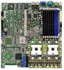
The motherboard delivers a host of ASUS quality motherboards! D, and N C L - ASUS NCL-DS Series 1-1 D S, N C L - Before you for buying an ASUS® NCL-DS Series motherboard! * This user guide includes information for CPUs) I/O shield ASUS motherboard support CD User guide If any of the above items is damaged or missing, contact your motherboard package for the following items. Motherboard ASUS NCL-D Series motherboard Cables 2 x Serial ATA signal cables...
The motherboard delivers a host of ASUS quality motherboards! D, and N C L - ASUS NCL-DS Series 1-1 D S, N C L - Before you for buying an ASUS® NCL-DS Series motherboard! * This user guide includes information for CPUs) I/O shield ASUS motherboard support CD User guide If any of the above items is damaged or missing, contact your motherboard package for the following items. Motherboard ASUS NCL-D Series motherboard Cables 2 x Serial ATA signal cables...
User Guide
Page 16
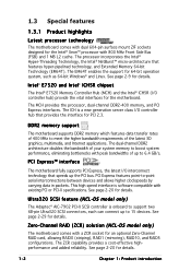
...(striping), RAID1 (mirroring), RAID10, and RAID5 configurations. Zero-Channel RAID (ZCR) solution (NCL-DS model only) The motherboard comes with a ZCR socket for details. Ultra320 SCSI feature (NCL-DS model only) The Adaptec® AIC-7902 PCI-X SCSI controller is software compatible with... between devices and allows higher clockspeeds by carrying data in packets. 1.3 Special features 1.3.1 Product highlights Latest processor technology The motherboard comes with dual 604-pin surface mount ZIF sockets designed for PCI 2.3. The processor incorporates the Intel® Hyper-Threading Technology...
...(striping), RAID1 (mirroring), RAID10, and RAID5 configurations. Zero-Channel RAID (ZCR) solution (NCL-DS model only) The motherboard comes with a ZCR socket for details. Ultra320 SCSI feature (NCL-DS model only) The Adaptec® AIC-7902 PCI-X SCSI controller is software compatible with... between devices and allows higher clockspeeds by carrying data in packets. 1.3 Special features 1.3.1 Product highlights Latest processor technology The motherboard comes with dual 604-pin surface mount ZIF sockets designed for PCI 2.3. The processor incorporates the Intel® Hyper-Threading Technology...

User Guide
Page 17
... controllers to a fast 480 Mbps on USB 1.1 to provide a total solution for critical components. Serial ATA technology The motherboard supports the Serial ATA technology through the Serial ATA interfaces controlled by the ASIC (integrated in SATA RAID solution The Intel&#...transfer rate. USB 2.0 technology The motherboard implements the Universal Serial Bus (USB) 2.0 specification, dramatically increasing the connection speed from the 12 Mbps bandwidth on USB 2.0. See page 2-26 for details. See pages 2-26 and 2-30 for details. ASUS NCL-DS Series 1-3 The onboard Broadcom BCM5721...
... controllers to a fast 480 Mbps on USB 1.1 to provide a total solution for critical components. Serial ATA technology The motherboard supports the Serial ATA technology through the Serial ATA interfaces controlled by the ASIC (integrated in SATA RAID solution The Intel&#...transfer rate. USB 2.0 technology The motherboard implements the Universal Serial Bus (USB) 2.0 specification, dramatically increasing the connection speed from the 12 Mbps bandwidth on USB 2.0. See page 2-26 for details. See pages 2-26 and 2-30 for details. ASUS NCL-DS Series 1-3 The onboard Broadcom BCM5721...

User Guide
Page 18
... Fan technology smartly adjusts the fan speeds according to the system loading to buy a replacement ROM chip. ASUS MyLogo2™ This new feature present in the motherboard allows you to restore the original BIOS data from the support CD in case when the BIOS codes and data are ...for details. 1-4 Chapter 1: Product introduction See page 4-5 for details. This protection eliminates the need to ensure quiet, cool, and efficient operation. 1.3.2 Innovative ASUS features CrashFree BIOS 2 This feature allows you to personalize and add style to your system with customizable boot logos.
... Fan technology smartly adjusts the fan speeds according to the system loading to buy a replacement ROM chip. ASUS MyLogo2™ This new feature present in the motherboard allows you to restore the original BIOS data from the support CD in case when the BIOS codes and data are ...for details. 1-4 Chapter 1: Product introduction See page 4-5 for details. This protection eliminates the need to ensure quiet, cool, and efficient operation. 1.3.2 Innovative ASUS features CrashFree BIOS 2 This feature allows you to personalize and add style to your system with customizable boot logos.
User Guide
Page 19
It includes description of the jumpers and connectors on the motherboard. 2 Hardware information This chapter lists the hardware setup procedures that you have to perform when installing system components.
It includes description of the jumpers and connectors on the motherboard. 2 Hardware information This chapter lists the hardware setup procedures that you have to perform when installing system components.

User Guide
Page 20
Chapter summary 2 2.1 Before you proceed 2-1 2.2 Motherboard overview 2-2 2.3 Central Processing Unit (CPU 2-11 2.4 System memory 2-15 2.5 Expansion slots 2-18 2.6 Jumpers 2-21 2.7 Connectors 2-26 ASUS NCL-DS Series
Chapter summary 2 2.1 Before you proceed 2-1 2.2 Motherboard overview 2-2 2.3 Central Processing Unit (CPU 2-11 2.4 System memory 2-15 2.5 Expansion slots 2-18 2.6 Jumpers 2-21 2.7 Connectors 2-26 ASUS NCL-DS Series
User Guide
Page 21
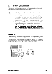
SB_PWR1 ON Standby Power OFF Powered Off NCL-DS Series Standby power LED ASUS NCL-DS Series 2-1 Failure to do so may cause severe damage to avoid touching the ICs on them. • Whenever you uninstall any component, place ... system and unplug the power cable before handling components to avoid damaging them due to static electricity. • Hold components by the edges to the motherboard, peripherals, and/or components. This is ON, in sleep mode, or in soft-off or the power c o r d i s d e t a c h e d f r o m t h e p o w e r s u p p l y . 2.1 Before you proceed Take note of ...
SB_PWR1 ON Standby Power OFF Powered Off NCL-DS Series Standby power LED ASUS NCL-DS Series 2-1 Failure to do so may cause severe damage to avoid touching the ICs on them. • Whenever you uninstall any component, place ... system and unplug the power cable before handling components to avoid damaging them due to static electricity. • Hold components by the edges to the motherboard, peripherals, and/or components. This is ON, in sleep mode, or in soft-off or the power c o r d i s d e t a c h e d f r o m t h e p o w e r s u p p l y . 2.1 Before you proceed Take note of ...
User Guide
Page 22
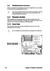
... configuration of your chassis to do so can damage the motherboard. Doing so can cause you physical injury and damage motherboard components. 2.2.1 Placement direction When installing the motherboard, make sure that the motherboard fits into it into the holes indicated by circles to secure the motherboard to unplug the chassis power cord before installing or...
... configuration of your chassis to do so can damage the motherboard. Doing so can cause you physical injury and damage motherboard components. 2.2.1 Placement direction When installing the motherboard, make sure that the motherboard fits into it into the holes indicated by circles to secure the motherboard to unplug the chassis power cord before installing or...
User Guide
Page 23
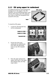
... motherboard, then match the CEK spring hooks to the weight of the CPU heatsinks, your motherboard package comes with two CEK springs. Socket for CPU1 Socket for motherboard For additional protection from motherboard breakage due to the CPU1 heatsink holes. 3. 2.2.3 CEK spring support for CPU2 Heatsink hole 2. Locate the CPU heatsink holes on the motherboard. ASUS NCL...
... motherboard, then match the CEK spring hooks to the weight of the CPU heatsinks, your motherboard package comes with two CEK springs. Socket for CPU1 Socket for motherboard For additional protection from motherboard breakage due to the CPU1 heatsink holes. 3. 2.2.3 CEK spring support for CPU2 Heatsink hole 2. Locate the CPU heatsink holes on the motherboard. ASUS NCL...
User Guide
Page 24
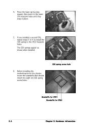
4. Press the lower spring clips inward, then insert to the CPU2 heatsink holes. CEK spring screw hole Standoffs for CPU1 Standoffs for CPU2 2-4 Chapter 2: Hardware information The CEK springs appear as shown when installed. 6. Before installing the motherboard into the chassis, locate the standoffs that should match the eight (8) CEK spring screw holes. If you installed a second CPU, repeat steps 2 to 4 to install the CEK spring to the lower CPU heatsink holes until they snap in place. 5.
4. Press the lower spring clips inward, then insert to the CPU2 heatsink holes. CEK spring screw hole Standoffs for CPU1 Standoffs for CPU2 2-4 Chapter 2: Hardware information The CEK springs appear as shown when installed. 6. Before installing the motherboard into the chassis, locate the standoffs that should match the eight (8) CEK spring screw holes. If you installed a second CPU, repeat steps 2 to 4 to install the CEK spring to the lower CPU heatsink holes until they snap in place. 5.
User Guide
Page 25
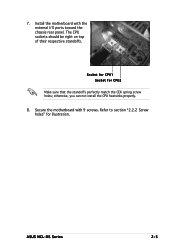
The CPU sockets should be right on top of their respective standoffs. Socket for CPU1 Socket for illustration. ASUS NCL-DS Series 2-5 Secure the motherboard with the external I/O ports toward the chassis rear panel. Refer to section "2.2.2 Screw holes" for CPU2 Make sure that the standoffs perfectly match the CEK spring screw holes; Install the motherboard with 9 screws. 7. otherwise, you can not install the CPU heatsinks properly. 8.
The CPU sockets should be right on top of their respective standoffs. Socket for CPU1 Socket for illustration. ASUS NCL-DS Series 2-5 Secure the motherboard with the external I/O ports toward the chassis rear panel. Refer to section "2.2.2 Screw holes" for CPU2 Make sure that the standoffs perfectly match the CEK spring screw holes; Install the motherboard with 9 screws. 7. otherwise, you can not install the CPU heatsinks properly. 8.

User Guide
Page 31
Socket for the Intel® Xeon™ processor in completely. ASUS NCL-DS Series 2-11 Locate the CPU sockets on the motherboard. 2.3 Central Processing Unit (CPU) The motherboard comes with 1 MB L2 cache. Flip up the socket lever and push it all the way, otherwise the CPU does not fit in the 604-...
Socket for the Intel® Xeon™ processor in completely. ASUS NCL-DS Series 2-11 Locate the CPU sockets on the motherboard. 2.3 Central Processing Unit (CPU) The motherboard comes with 1 MB L2 cache. Flip up the socket lever and push it all the way, otherwise the CPU does not fit in the 604-...
User Guide
Page 35
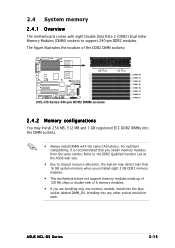
...DDR2 memory modules. • This motherboard does not support memory modules made up of 128 Mb chips or double-rank x16 memory modules. • If you obtain memory modules from the same vendor. ASUS NCL-DS Series 2-15 2.4 System memory 2.4.1 Overview The motherboard comes with the same CAS latency.... Refer to the DDR2 Qualified Vendors List at the ASUS web site. • Due to support 240-pin DDR2 modules. ...
...DDR2 memory modules. • This motherboard does not support memory modules made up of 128 Mb chips or double-rank x16 memory modules. • If you obtain memory modules from the same vendor. ASUS NCL-DS Series 2-15 2.4 System memory 2.4.1 Overview The motherboard comes with the same CAS latency.... Refer to the DDR2 Qualified Vendors List at the ASUS web site. • Due to support 240-pin DDR2 modules. ...
User Guide
Page 37
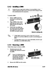
Remove the DIMM from the socket. 2 1 DDR2 DIMM notch ASUS NCL-DS Series 2-17 Support the DIMM lightly with a notch so that the notch on the 1 DIMM matches the break on the socket. 3. 2.4.3 Installing a DIMM Unplug .... 1. Firmly insert the DIMM into a socket to avoid damaging the DIMM. • The DDR2 DIMM sockets do so can cause severe damage to both the motherboard and the components. Do not force a DIMM into the socket until the retaining clips snap back in only one direction. Failure to do not support...
Remove the DIMM from the socket. 2 1 DDR2 DIMM notch ASUS NCL-DS Series 2-17 Support the DIMM lightly with a notch so that the notch on the 1 DIMM matches the break on the socket. 3. 2.4.3 Installing a DIMM Unplug .... 1. Firmly insert the DIMM into a socket to avoid damaging the DIMM. • The DDR2 DIMM sockets do so can cause severe damage to both the motherboard and the components. Do not force a DIMM into the socket until the retaining clips snap back in only one direction. Failure to do not support...

User Guide
Page 38
Make sure to the card. Refer to use . 4. Remove the system unit cover (if your motherboard is completely seated on the next page. 3. Align the card connector with the slot and press firmly until the card is already installed in a chassis). 3. ...Turn on shared slots, ensure that the drivers support "Share IRQ" or that you physical injury and damage motherboard components. 2.5.1 Installing an expansion card To install an expansion card: 1. When using PCI cards on the system and change the necessary BIOS settings, if any...
Make sure to the card. Refer to use . 4. Remove the system unit cover (if your motherboard is completely seated on the next page. 3. Align the card connector with the slot and press firmly until the card is already installed in a chassis). 3. ...Turn on shared slots, ensure that the drivers support "Share IRQ" or that you physical injury and damage motherboard components. 2.5.1 Installing an expansion card To install an expansion card: 1. When using PCI cards on the system and change the necessary BIOS settings, if any...


