NCCH-DR User Manual English Version
Page 4
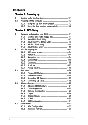
... switch 3-2 Chapter 4: BIOS Setup 4.1 Managing and updating your BIOS 4-1 4.1.1 Creating a bootable floppy disk 4-1 4.1.2 AwardBIOS Flash Utility 4-3 4.1.3 ASUS CrashFree BIOS 2 utility 4-7 4.1.4 ASUS EZ Flash utility 4-9 4.1.5 ASUS Update utility 4-10 4.2 BIOS Setup program 4-13 4.2.1 BIOS menu screen 4-14 4.2.2...Slave 4-19 4.3.3 Secondary IDE Master 4-19 4.3.4 Secondary IDE Slave 4-19 4.4 Advanced menu 4-20 4.4.1 4.4.2 4.4.3 Advanced BIOS Features 4-21 CPU Configuration 4-22 Memory Configuration 4-23 4.4.4 Chipset 4-24 4.4.5 Onboard Device 4-25 4.4.6 PCIPnP 4-29 4.4.7...
... switch 3-2 Chapter 4: BIOS Setup 4.1 Managing and updating your BIOS 4-1 4.1.1 Creating a bootable floppy disk 4-1 4.1.2 AwardBIOS Flash Utility 4-3 4.1.3 ASUS CrashFree BIOS 2 utility 4-7 4.1.4 ASUS EZ Flash utility 4-9 4.1.5 ASUS Update utility 4-10 4.2 BIOS Setup program 4-13 4.2.1 BIOS menu screen 4-14 4.2.2...Slave 4-19 4.3.3 Secondary IDE Master 4-19 4.3.4 Secondary IDE Slave 4-19 4.4 Advanced menu 4-20 4.4.1 4.4.2 4.4.3 Advanced BIOS Features 4-21 CPU Configuration 4-22 Memory Configuration 4-23 4.4.4 Chipset 4-24 4.4.5 Onboard Device 4-25 4.4.6 PCIPnP 4-29 4.4.7...
NCCH-DR User Manual English Version
Page 8
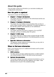
...Product introduction This chapter describes the features of shutting down the system. • Chapter 4: BIOS setup This chapter tells how to perform when installing system components. ASUS websites The ASUS website provides updated information on the motherboard. • Chapter 3: Powering up This chapter ... Chapter 2: Hardware information This chapter lists the hardware setup procedures that you may have to change system settings through the BIOS Setup menus. Refer to when configuring the motherboard. These documents are also provided. • Appendix: Reference information This ...
...Product introduction This chapter describes the features of shutting down the system. • Chapter 4: BIOS setup This chapter tells how to perform when installing system components. ASUS websites The ASUS website provides updated information on the motherboard. • Chapter 3: Powering up This chapter ... Chapter 2: Hardware information This chapter lists the hardware setup procedures that you may have to change system settings through the BIOS Setup menus. Refer to when configuring the motherboard. These documents are also provided. • Appendix: Reference information This ...

NCCH-DR User Manual English Version
Page 10
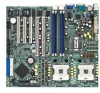
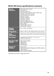
...1.1 (12 Mbps) 8Mb Flash ROM, Award BIOS, PnP, DMI, WfM2.0, SM BIOS2.3 1 x PS/2 keyboard port 1 x PS/2 mouse port 2 x USB 2.0 ports 1 x Serial port 1 x Video port 2 x Gigabit LAN (RJ-45) ports (continued on the next page) x NCCH-DR Series specifications summary CPU Chipset Front Side Bus ...Memory Expansion slots Storage LAN USB BIOS features Rear panel Support for dual Intel® Xeon™ Processors up to 4.4+ GHz with Hyper-Threading ...
...1.1 (12 Mbps) 8Mb Flash ROM, Award BIOS, PnP, DMI, WfM2.0, SM BIOS2.3 1 x PS/2 keyboard port 1 x PS/2 mouse port 2 x USB 2.0 ports 1 x Serial port 1 x Video port 2 x Gigabit LAN (RJ-45) ports (continued on the next page) x NCCH-DR Series specifications summary CPU Chipset Front Side Bus ...Memory Expansion slots Storage LAN USB BIOS features Rear panel Support for dual Intel® Xeon™ Processors up to 4.4+ GHz with Hyper-Threading ...
NCCH-DR User Manual English Version
Page 11
... power plugs) Extended ATX form factor: 12 in x 10.5 in (30.5 cm x 26.7 cm) ASUS CrashFree BIOS 2 ASUS Q-Fan 2 ASUS EZFLash ASUS MyLogo 2 Device drivers ASUS Server Web-based Management (ASWM) software System utilities ASUS contact information *Specifications are subject to change without notice. NCCH-DR Series specifications summary Internal connectors Industry standard Manageability Power Requirement Form Factor Innovative...
... power plugs) Extended ATX form factor: 12 in x 10.5 in (30.5 cm x 26.7 cm) ASUS CrashFree BIOS 2 ASUS Q-Fan 2 ASUS EZFLash ASUS MyLogo 2 Device drivers ASUS Server Web-based Management (ASWM) software System utilities ASUS contact information *Specifications are subject to change without notice. NCCH-DR Series specifications summary Internal connectors Industry standard Manageability Power Requirement Form Factor Innovative...
NCCH-DR User Manual English Version
Page 18
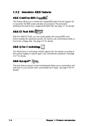
... smartly adjusts the fan speeds according to the system loading to buy a replacement ROM chip. ASUS MyLogo2™ This new feature present in case when the BIOS codes and data are corrupted. ASUS EZ Flash BIOS With the ASUS EZ Flash, you to personalize and add style to use a DOS-based utility or boot from...
... smartly adjusts the fan speeds according to the system loading to buy a replacement ROM chip. ASUS MyLogo2™ This new feature present in case when the BIOS codes and data are corrupted. ASUS EZ Flash BIOS With the ASUS EZ Flash, you to personalize and add style to use a DOS-based utility or boot from...
NCCH-DR User Manual English Version
Page 31
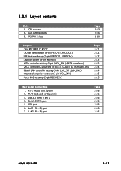
...; Serial (COM1) port 5. LAN1 (RJ-45) port 7. VGA port 6. LAN2 (RJ-45) port Page 2-26 2-26 2-26 2-26 2-26 2-26 2-26 ASUS NCCH-DR 2-11 LAN_EN2) Integrated graphics controller (3-pin VGA_EN1) Force BIOS recovery (3-pin RECOVERY) Page 2-21 2-22 2-22 2-23 2-23 2-24 2-24 2-25 2-25 Rear panel connectors 1. PS/2 keyboard port (purple) 3. DDR...
...; Serial (COM1) port 5. LAN1 (RJ-45) port 7. VGA port 6. LAN2 (RJ-45) port Page 2-26 2-26 2-26 2-26 2-26 2-26 2-26 ASUS NCCH-DR 2-11 LAN_EN2) Integrated graphics controller (3-pin VGA_EN1) Force BIOS recovery (3-pin RECOVERY) Page 2-21 2-22 2-22 2-23 2-23 2-24 2-24 2-25 2-25 Rear panel connectors 1. PS/2 keyboard port (purple) 3. DDR...

NCCH-DR User Manual English Version
Page 39
... card. Turn on the next page. 3. Refer to use . 4. ASUS NCCH-DR 2-19 2.5 Expansion slots In the future, you may cause you physical injury and damage motherboard components. 2.5.1 Installing an expansion card To install an expansion card: 1. Keep the screw for information on BIOS setup. 2. See Chapter 4 for later use . Remove the system unit...
... card. Turn on the next page. 3. Refer to use . 4. ASUS NCCH-DR 2-19 2.5 Expansion slots In the future, you may cause you physical injury and damage motherboard components. 2.5.1 Installing an expansion card To install an expansion card: 1. Keep the screw for information on BIOS setup. 2. See Chapter 4 for later use . Remove the system unit...
NCCH-DR User Manual English Version
Page 41
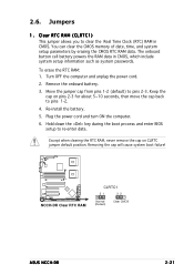
... the computer and unplug the power cord. 2. Removing the cap will cause system boot failure! NCCH-DR NCCH-DR Clear RTC RAM CLRTC1 21 32 Normal (Default) Clear CMOS ASUS NCCH-DR 2-21 Hold down the key during the boot process and enter BIOS setup to pins 2-3. You can clear the CMOS memory of date, time, and system...
... the computer and unplug the power cord. 2. Removing the cap will cause system boot failure! NCCH-DR NCCH-DR Clear RTC RAM CLRTC1 21 32 Normal (Default) Clear CMOS ASUS NCCH-DR 2-21 Hold down the key during the boot process and enter BIOS setup to pins 2-3. You can clear the CMOS memory of date, time, and system...

NCCH-DR User Manual English Version
Page 43
... that can supply at least 1A on the keyboard (the default is the Space Bar). KBPWR1 12 23 +5V (Default) +5VSB NCCH-DR NCCH-DR Keyboard power setting 5. NCCH-DR NCCH-DR SATA_EN setting SATA_EN1 3 2 2 1 Enable (Default) Disable ASUS NCCH-DR 2-23 Keyboard power (3-pin KBPWR1) This jumper allows you to wake up feature. Set this jumper to pins 2-3 (+5VSB) to... controller. 4. SATA controller setting (3-pin SATA_EN1) On SATA models only These jumpers allow you press a key on the +5VSB lead, and a corresponding setting in the BIOS.
... that can supply at least 1A on the keyboard (the default is the Space Bar). KBPWR1 12 23 +5V (Default) +5VSB NCCH-DR NCCH-DR Keyboard power setting 5. NCCH-DR NCCH-DR SATA_EN setting SATA_EN1 3 2 2 1 Enable (Default) Disable ASUS NCCH-DR 2-23 Keyboard power (3-pin KBPWR1) This jumper allows you to wake up feature. Set this jumper to pins 2-3 (+5VSB) to... controller. 4. SATA controller setting (3-pin SATA_EN1) On SATA models only These jumpers allow you press a key on the +5VSB lead, and a corresponding setting in the BIOS.

NCCH-DR User Manual English Version
Page 45
... the jumper back to pins 2-3. 3. LED 0 LED1 RECOVERY PANEL1 RECOVERY 12 23 Normal (Default) NCCH-DR NCCH-DR BIOS recovery setting BIOS Recovery ASUS NCCH-DR 2-25 Shut down the system. 5. Integrated graphics controller (3-pin VGA_EN1) This jumper allows you to update or recover the BIOS settings when it gets corrupted or destroyed.This jumper allows you enable or disable...
... the jumper back to pins 2-3. 3. LED 0 LED1 RECOVERY PANEL1 RECOVERY 12 23 Normal (Default) NCCH-DR NCCH-DR BIOS recovery setting BIOS Recovery ASUS NCCH-DR 2-25 Shut down the system. 5. Integrated graphics controller (3-pin VGA_EN1) This jumper allows you to update or recover the BIOS settings when it gets corrupted or destroyed.This jumper allows you enable or disable...
NCCH-DR User Manual English Version
Page 48
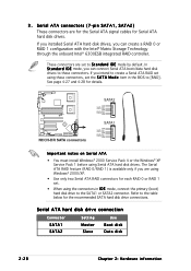
... t a n d a r d I D E mode, you intend to create a Serial ATA RAID set . • When using the connectors in the BIOS to the table below for details. Refer to [RAID]. Serial ATA hard disk drive connection Connector SATA1 SATA2 Setting Master Slave Use Boot disk Data...0 or RAID 1 configuration with the Intel® Matrix Storage Technology through the onboard Intel® 6300ESB integrated RAID controller. NCCH-DR NCCH-DR SATA connectors SATA2 GND RSATA_TXP2 RSATA_TXN2 GND RSATA_RXN2 RSATA_RXP2 GND SATA1 GND RSATA_TXP1 RSATA_TXN1 GND RSATA_RXN1 RSATA_RXP1 GND Important notes on Serial ...
... t a n d a r d I D E mode, you intend to create a Serial ATA RAID set . • When using the connectors in the BIOS to the table below for details. Refer to [RAID]. Serial ATA hard disk drive connection Connector SATA1 SATA2 Setting Master Slave Use Boot disk Data...0 or RAID 1 configuration with the Intel® Matrix Storage Technology through the onboard Intel® 6300ESB integrated RAID controller. NCCH-DR NCCH-DR SATA connectors SATA2 GND RSATA_TXP2 RSATA_TXN2 GND RSATA_RXN2 RSATA_RXP2 GND SATA1 GND RSATA_TXP1 RSATA_TXN1 GND RSATA_RXN1 RSATA_RXP1 GND Important notes on Serial ...

NCCH-DR User Manual English Version
Page 49
... cannot enter the RAID utility and SATA BIOS setup during POST. 5 . GND RSATA_TXP6 RSATA_TXN6 GND RSATA_RXN6 RSATA_RXP6 GND GND RSATA_TXP5 RSATA_TXN5 GND RSATA_RXN5 RSATA_RXP5 GND GND RSATA_TXP4 RSATA_TXN4 GND RSATA_RXN4 RSATA_RXP4 GND NCCH-DR NCCH-DR SATA RAID connectors GND RSATA_TXP3 RSATA_TXN3 GND ...to go through the Adaptec AIC-8130 SATA RAID controller. HDLED1 1 NC ADD_IN_CARD_ACT# ADD_IN_CARD_ACT# NC NCCH-DR NCCH-DR SCSI/SATA card activity LED connector ASUS NCCH-DR 2-29 otherwise, you have connected the Serial ATA signal cable and installed Serial ATA hard disk drives;
... cannot enter the RAID utility and SATA BIOS setup during POST. 5 . GND RSATA_TXP6 RSATA_TXN6 GND RSATA_RXN6 RSATA_RXP6 GND GND RSATA_TXP5 RSATA_TXN5 GND RSATA_RXN5 RSATA_RXP5 GND GND RSATA_TXP4 RSATA_TXN4 GND RSATA_RXN4 RSATA_RXP4 GND NCCH-DR NCCH-DR SATA RAID connectors GND RSATA_TXP3 RSATA_TXN3 GND ...to go through the Adaptec AIC-8130 SATA RAID controller. HDLED1 1 NC ADD_IN_CARD_ACT# ADD_IN_CARD_ACT# NC NCCH-DR NCCH-DR SCSI/SATA card activity LED connector ASUS NCCH-DR 2-29 otherwise, you have connected the Serial ATA signal cable and installed Serial ATA hard disk drives;

NCCH-DR User Manual English Version
Page 55
... NC PLEDMLED+ MLEDNC +5V GND GND SPKROUT HDLED+ GND NMIBTN# GND PWRBTN# GND NC FP_RESET# GND NCCH-DR NCCH-DR System panel connector HDD LED NMI Button RESET PWRSW The sytem panel connector is for the system power button....operating system is loaded. • System warning speaker (Orange 4-pin SPEAKER) This 4-pin connector is for easy connection. ASUS NCCH-DR 2-35 15. Refer to the front panel message LED. Connect the chassis power LED cable to this connector. The ... connector supports several chassis-mounted functions. The speaker allows you turn on the BIOS settings.
... NC PLEDMLED+ MLEDNC +5V GND GND SPKROUT HDLED+ GND NMIBTN# GND PWRBTN# GND NC FP_RESET# GND NCCH-DR NCCH-DR System panel connector HDD LED NMI Button RESET PWRSW The sytem panel connector is for the system power button....operating system is loaded. • System warning speaker (Orange 4-pin SPEAKER) This 4-pin connector is for easy connection. ASUS NCCH-DR 2-35 15. Refer to the front panel message LED. Connect the chassis power LED cable to this connector. The ... connector supports several chassis-mounted functions. The speaker allows you turn on the BIOS settings.
NCCH-DR User Manual English Version
Page 59
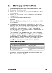
...High frequency beeps when system is equipped with the last device on test. ASUS NCCH-DR 3-1 Connect the power cord to a power outlet that all the connections, replace the system case cover. 2. If you do not see BIOS beep codes table below) or additional messages appear on the system front ...panel case lights up. Connect the power cord to enter the BIOS Setup. External SCSI devices (starting with a surge protector. 5. If your retailer for the first time 1. At power on . After applying power, ...
...High frequency beeps when system is equipped with the last device on test. ASUS NCCH-DR 3-1 Connect the power cord to a power outlet that all the connections, replace the system case cover. 2. If you do not see BIOS beep codes table below) or additional messages appear on the system front ...panel case lights up. Connect the power cord to enter the BIOS Setup. External SCSI devices (starting with a surge protector. 5. If your retailer for the first time 1. At power on . After applying power, ...
NCCH-DR User Manual English Version
Page 60
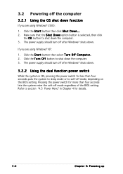
...section "4.5 Power Menu" in Chapter 4 for more than four seconds puts the system to sleep mode or to soft-off mode, depending on the BIOS setting. 3.2 Powering off the computer 3.2.1 Using the OS shut down function If you are using Windows® XP: 1. The power supply should turn off... function power switch While the system is selected, then click the O K button to shut down . The power supply should turn off mode regardless of the BIOS setting. Make sure that the S h u t D o w n option button is ON, pressing the power switch for less than four seconds lets the system enter the...
...section "4.5 Power Menu" in Chapter 4 for more than four seconds puts the system to sleep mode or to soft-off mode, depending on the BIOS setting. 3.2 Powering off the computer 3.2.1 Using the OS shut down function If you are using Windows® XP: 1. The power supply should turn off... function power switch While the system is selected, then click the O K button to shut down . The power supply should turn off mode regardless of the BIOS setting. Make sure that the S h u t D o w n option button is ON, pressing the power switch for less than four seconds lets the system enter the...
NCCH-DR User Manual English Version
Page 61
This chapter tells how to change the system settings through the BIOS Setup menus. Detailed descriptions of the BIOS parameters are also provided. 4 BIOS setup
This chapter tells how to change the system settings through the BIOS Setup menus. Detailed descriptions of the BIOS parameters are also provided. 4 BIOS setup

NCCH-DR User Manual English Version
Page 62
Chapter summary 4 4.1 Managing and updating your BIOS 4-1 4.2 BIOS Setup program 4-13 4.3 Main menu 4-16 4.4 Advanced menu 4-20 4.5 Power menu 4-32 4.6 Boot menu 4-38 4.7 Exit menu 4-44 ASUS NCCH-DR
Chapter summary 4 4.1 Managing and updating your BIOS 4-1 4.2 BIOS Setup program 4-13 4.3 Main menu 4-16 4.4 Advanced menu 4-20 4.5 Power menu 4-32 4.6 Boot menu 4-38 4.7 Exit menu 4-44 ASUS NCCH-DR

NCCH-DR User Manual English Version
Page 63
... S t a r t. A w a r d B I O S 2 (Updates the BIOS using a floppy disk or the motherboard support CD.) 4. Insert a 1.44 MB floppy disk to the floppy disk drive. c. b. W i n d o w s® X P u s e r s : Select C r e a t e a n M S - 4.1 Managing and updating your BIOS The following to create a bootable floppy disk. Insert a 1.44MB floppy disk into the drive. Copy the original motherboard BIOS using a floppy disk.) 2. ASUS NCCH-DR 4-1 Windows® XP...
... S t a r t. A w a r d B I O S 2 (Updates the BIOS using a floppy disk or the motherboard support CD.) 4. Insert a 1.44 MB floppy disk to the floppy disk drive. c. b. W i n d o w s® X P u s e r s : Select C r e a t e a n M S - 4.1 Managing and updating your BIOS The following to create a bootable floppy disk. Insert a 1.44MB floppy disk into the drive. Copy the original motherboard BIOS using a floppy disk.) 2. ASUS NCCH-DR 4-1 Windows® XP...
NCCH-DR User Manual English Version
Page 64
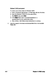
Insert the Windows® 2000 CD to the bootable floppy disk. 4-2 Chapter 4: BIOS setup Copy the original or the latest motherboard BIOS file to the optical drive. b. d. In the O p e n field, type D:\bootdisk\makeboot a: assuming that D is your optical drive letter. Insert a formatted, high density 1.44 MB floppy disk into the drive. c. Click S t a r t, then select R u n. Windows® 2000 environment To create a set of boot disks for Windows® 2000: a. Press , then follow screen instructions to continue. 2. e.
Insert the Windows® 2000 CD to the bootable floppy disk. 4-2 Chapter 4: BIOS setup Copy the original or the latest motherboard BIOS file to the optical drive. b. d. In the O p e n field, type D:\bootdisk\makeboot a: assuming that D is your optical drive letter. Insert a formatted, high density 1.44 MB floppy disk into the drive. c. Click S t a r t, then select R u n. Windows® 2000 environment To create a set of boot disks for Windows® 2000: a. Press , then follow screen instructions to continue. 2. e.
NCCH-DR User Manual English Version
Page 65
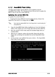
..., then save it to save the current BIOS file. When the A:> appears, replace the bootable floppy disk with the latest BIOS file. 3. AwardBIOS Flash Utility for ASUS V1.05 (C) Phoenix Technologies Ltd. ASUS NCCH-DR 4-3 Download the latest BIOS file from the Software folder of the support... CD to avoid loading the wrong BIOS file. 2. B I N. Boot the system in...
..., then save it to save the current BIOS file. When the A:> appears, replace the bootable floppy disk with the latest BIOS file. 3. AwardBIOS Flash Utility for ASUS V1.05 (C) Phoenix Technologies Ltd. ASUS NCCH-DR 4-3 Download the latest BIOS file from the Software folder of the support... CD to avoid loading the wrong BIOS file. 2. B I N. Boot the system in...


