
NCCH-DR User Manual English Version
Page 3
Contents Notices vi Safety information vii About this guide viii Typography ix NCCH-DR Series specifications summary x Chapter 1: Product introduction 1.1 Welcome 1-1 1.2 Package contents 1-1 1.3 Special features 1-2 1.3.1 Product highlights 1-2 1.3.2 Innovative ASUS features 1-4 Chapter 2: Hardware information 2.1 Before you proceed 2-1 2.2 Motherboard overview 2-2 2.2.1 2.2.2 2.2.3 Placement direction 2-2 Screw holes 2-2 CPU heatsink weight support 2-3 2.2.4 Motherboard layout 2-9 2.2.5 Layout contents 2-11 2.3 Central Processing Unit...
Contents Notices vi Safety information vii About this guide viii Typography ix NCCH-DR Series specifications summary x Chapter 1: Product introduction 1.1 Welcome 1-1 1.2 Package contents 1-1 1.3 Special features 1-2 1.3.1 Product highlights 1-2 1.3.2 Innovative ASUS features 1-4 Chapter 2: Hardware information 2.1 Before you proceed 2-1 2.2 Motherboard overview 2-2 2.2.1 2.2.2 2.2.3 Placement direction 2-2 Screw holes 2-2 CPU heatsink weight support 2-3 2.2.4 Motherboard layout 2-9 2.2.5 Layout contents 2-11 2.3 Central Processing Unit...
NCCH-DR User Manual English Version
Page 4
...Setup 4.1 Managing and updating your BIOS 4-1 4.1.1 Creating a bootable floppy disk 4-1 4.1.2 AwardBIOS Flash Utility 4-3 4.1.3 ASUS CrashFree BIOS 2 utility 4-7 4.1.4 ASUS EZ Flash utility 4-9 4.1.5 ASUS Update utility 4-10 4.2 BIOS Setup program 4-13 4.2.1 BIOS menu screen 4-14 4.2.2 Menu bar 4-14 4.2.3 ...Secondary IDE Slave 4-19 4.4 Advanced menu 4-20 4.4.1 4.4.2 4.4.3 Advanced BIOS Features 4-21 CPU Configuration 4-22 Memory Configuration 4-23 4.4.4 Chipset 4-24 4.4.5 Onboard Device 4-25 4.4.6 PCIPnP 4-29 4.4.7 USB Configuration 4-31 4.5 Power menu 4-32 4.5.1 ...
...Setup 4.1 Managing and updating your BIOS 4-1 4.1.1 Creating a bootable floppy disk 4-1 4.1.2 AwardBIOS Flash Utility 4-3 4.1.3 ASUS CrashFree BIOS 2 utility 4-7 4.1.4 ASUS EZ Flash utility 4-9 4.1.5 ASUS Update utility 4-10 4.2 BIOS Setup program 4-13 4.2.1 BIOS menu screen 4-14 4.2.2 Menu bar 4-14 4.2.3 ...Secondary IDE Slave 4-19 4.4 Advanced menu 4-20 4.4.1 4.4.2 4.4.3 Advanced BIOS Features 4-21 CPU Configuration 4-22 Memory Configuration 4-23 4.4.4 Chipset 4-24 4.4.5 Onboard Device 4-25 4.4.6 PCIPnP 4-29 4.4.7 USB Configuration 4-31 4.5 Power menu 4-32 4.5.1 ...

NCCH-DR User Manual English Version
Page 10
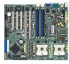
...2 x USB 2.0 ports 1 x Serial port 1 x Video port 2 x Gigabit LAN (RJ-45) ports (continued on the next page) x NCCH-DR Series specifications summary CPU Chipset Front Side Bus Memory Expansion slots Storage LAN USB BIOS features Rear panel Support for dual Intel® Xeon™ Processors up to 4.4+ GHz with... Hyper-Threading Technology Support for Extended Memory 64-bit Technology (EM64T) On-die 1MB L2 cache North bridge: Intel® E7210 Memory Controller Hub (MCH) South bridge: Intel® 6300ESB I/O Controller Hub (ICH) 800 MHz...
...2 x USB 2.0 ports 1 x Serial port 1 x Video port 2 x Gigabit LAN (RJ-45) ports (continued on the next page) x NCCH-DR Series specifications summary CPU Chipset Front Side Bus Memory Expansion slots Storage LAN USB BIOS features Rear panel Support for dual Intel® Xeon™ Processors up to 4.4+ GHz with... Hyper-Threading Technology Support for Extended Memory 64-bit Technology (EM64T) On-die 1MB L2 cache North bridge: Intel® E7210 Memory Controller Hub (MCH) South bridge: Intel® 6300ESB I/O Controller Hub (ICH) 800 MHz...

NCCH-DR User Manual English Version
Page 16
... requirement, and up to 2-29 for details. See page 2-13 for details. The motherboard supports up to 4 GB of system memory using PC3200/PC2700 ECC or non-ECC DDR DIMMs to deliver up to 150 MB/s data transfer rate for 6300ESB and 300 MB/s...0 and RAID 1 configuration for the motherboard. See page 2-29 for details. Dual-channel memory support Employing the dual-channel DDR memory architecture, the motherboard provides a solution that features hyper-pipelined technology, and Extended Memory 64-bit Technology (EM64T). See page 2-16 for details. 1-2 Chapter 1: Product introduction ...
... requirement, and up to 2-29 for details. See page 2-13 for details. The motherboard supports up to 4 GB of system memory using PC3200/PC2700 ECC or non-ECC DDR DIMMs to deliver up to 150 MB/s data transfer rate for 6300ESB and 300 MB/s...0 and RAID 1 configuration for the motherboard. See page 2-29 for details. Dual-channel memory support Employing the dual-channel DDR memory architecture, the motherboard provides a solution that features hyper-pipelined technology, and Extended Memory 64-bit Technology (EM64T). See page 2-16 for details. 1-2 Chapter 1: Product introduction ...
NCCH-DR User Manual English Version
Page 17
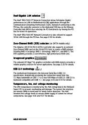
...to prevent overheating and damage. The system fan rotations per minute (RPM) is monitored by freeing the PCI bus for timely failure detection. ASUS NCCH-DR 1-3 Integrated graphics The onboard ATI Rage™ XL graphics controller with USB 1.1. See page 2-26 for details. USB 2.0 technology The ...32-bit LAN through the Communication Streaming Architecture (CSA). The Intel® PRO/1000 MT Network Connection is backward compatible with 8MB memory provides a reliable graphics solution for critical components. See page 2-26 and 2-30 for details. See page 4-36 and 4-37 for...
...to prevent overheating and damage. The system fan rotations per minute (RPM) is monitored by freeing the PCI bus for timely failure detection. ASUS NCCH-DR 1-3 Integrated graphics The onboard ATI Rage™ XL graphics controller with USB 1.1. See page 2-26 for details. USB 2.0 technology The ...32-bit LAN through the Communication Streaming Architecture (CSA). The Intel® PRO/1000 MT Network Connection is backward compatible with 8MB memory provides a reliable graphics solution for critical components. See page 2-26 and 2-30 for details. See page 4-36 and 4-37 for...

NCCH-DR User Manual English Version
Page 20
Jumpers 2-21 2.7 Connectors 2-26 ASUS NCCH-DR Chapter summary 2 2.1 Before you proceed 2-1 2.2 Motherboard overview 2-2 2.3 Central Processing Unit (CPU 2-13 2.4 System memory 2-16 2.5 Expansion slots 2-19 2.6.
Jumpers 2-21 2.7 Connectors 2-26 ASUS NCCH-DR Chapter summary 2 2.1 Before you proceed 2-1 2.2 Motherboard overview 2-2 2.3 Central Processing Unit (CPU 2-13 2.4 System memory 2-16 2.5 Expansion slots 2-19 2.6.

NCCH-DR User Manual English Version
Page 36
...in Table 1. • Always install DIMMs with four Double Data Rate (DDR) Dual Inline Memory Modules (DIMM) sockets. Refer to the DDR Qualified Vendors List on the the ASUS website for details. • In dual-channel configurations, install only identical (the same type and... Three DDR DIMMs installed into any of the DDR DIMM sockets: 104 Pins 80 Pins NCCH-DR NCCH-DR 184-Pin DDR DIMM sockets DIMM_A1 DIMM_A2 DIMM_B1 DIMM_B2 2.4.2 Memory configurations You may cause memory sizing error or system boot failure. The following figure illustrates the location of the recommended ...
...in Table 1. • Always install DIMMs with four Double Data Rate (DDR) Dual Inline Memory Modules (DIMM) sockets. Refer to the DDR Qualified Vendors List on the the ASUS website for details. • In dual-channel configurations, install only identical (the same type and... Three DDR DIMMs installed into any of the DDR DIMM sockets: 104 Pins 80 Pins NCCH-DR NCCH-DR 184-Pin DDR DIMM sockets DIMM_A1 DIMM_A2 DIMM_B1 DIMM_B2 2.4.2 Memory configurations You may cause memory sizing error or system boot failure. The following figure illustrates the location of the recommended ...

NCCH-DR User Manual English Version
Page 37
Table 1: Recommended memory configurations Mode Single-channel (DDR400/DDR333) Dual-channel (DDR400/DDR333) (1) (2) (3) (4) (1) (2) (3)* Sockets DIMM_A1 DIMM_A2 DIMM_B1 DIMM_B2 (black) (blue) (black) (blue) Populated - - - - Populated - - Populated - - - - Populated - Populated Populated - ... DIMMs in all four sockets, or • install identical DIMMs in DIMM_A1 and DIMM_B1 (black sockets) and identical DIMMs in DIMM_A2 and DIMM_B2 (blue sockets) ASUS NCCH-DR 2-17
Table 1: Recommended memory configurations Mode Single-channel (DDR400/DDR333) Dual-channel (DDR400/DDR333) (1) (2) (3) (4) (1) (2) (3)* Sockets DIMM_A1 DIMM_A2 DIMM_B1 DIMM_B2 (black) (blue) (black) (blue) Populated - - - - Populated - - Populated - - - - Populated - Populated Populated - ... DIMMs in all four sockets, or • install identical DIMMs in DIMM_A1 and DIMM_B1 (black sockets) and identical DIMMs in DIMM_A2 and DIMM_B2 (blue sockets) ASUS NCCH-DR 2-17
NCCH-DR User Manual English Version
Page 41
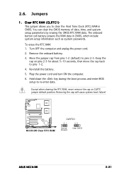
... cap from pins 1-2 (default) to re-enter data. You can clear the CMOS memory of date, time, and system setup parameters by erasing the CMOS RTC RAM data. NCCH-DR NCCH-DR Clear RTC RAM CLRTC1 21 32 Normal (Default) Clear CMOS ASUS NCCH-DR 2-21 Keep the cap on CLRTC jumper default position. 2.6. Clear RTC RAM (CLRTC1...
... cap from pins 1-2 (default) to re-enter data. You can clear the CMOS memory of date, time, and system setup parameters by erasing the CMOS RTC RAM data. NCCH-DR NCCH-DR Clear RTC RAM CLRTC1 21 32 Normal (Default) Clear CMOS ASUS NCCH-DR 2-21 Keep the cap on CLRTC jumper default position. 2.6. Clear RTC RAM (CLRTC1...

NCCH-DR User Manual English Version
Page 66
... - If you to Program : 1001.bin Program Flashing Memory - 0FE00 OK 11112222333344445555666677778888999900001111222233334444555566667777888899990000111122223333444455556666777788889999000011112222111122223333444455556666777788889999000011112222 Write OK No Update Write Fail Warning: Don't Turn Off Power Or Reset System! 9. NCCH-DRC-00 DATE: 07/14/2004 Flash Type - The...turn off or reset the system during the flashing process! See the next section for ASUS V1.05 (C) Phoenix Technologies Ltd. After the flashing process is completed, press to Program field, then press ....
... - If you to Program : 1001.bin Program Flashing Memory - 0FE00 OK 11112222333344445555666677778888999900001111222233334444555566667777888899990000111122223333444455556666777788889999000011112222111122223333444455556666777788889999000011112222 Write OK No Update Write Fail Warning: Don't Turn Off Power Or Reset System! 9. NCCH-DRC-00 DATE: 07/14/2004 Flash Type - The...turn off or reset the system during the flashing process! See the next section for ASUS V1.05 (C) Phoenix Technologies Ltd. After the flashing process is completed, press to Program field, then press ....

NCCH-DR User Manual English Version
Page 76
... Legacy Diskette A Floppy 3 Mode Support Primary IDE Master Primary IDE Slave Secondary IDE Master Secondary IDE Slave Third IDE Master Fourth IDE Master Base Memory Extended Memory Total Memory 11: 10 : 30 Wed, Jul 21 2004 [1.44M, 3.5 in the menu and change the settings. Navigation keys Field settings 4.2.2 Menu bar The menu bar...
... Legacy Diskette A Floppy 3 Mode Support Primary IDE Master Primary IDE Slave Secondary IDE Master Secondary IDE Slave Third IDE Master Fourth IDE Master Base Memory Extended Memory Total Memory 11: 10 : 30 Wed, Jul 21 2004 [1.44M, 3.5 in the menu and change the settings. Navigation keys Field settings 4.2.2 Menu bar The menu bar...

NCCH-DR User Manual English Version
Page 78
...Floppy 3 Mode Support Primary IDE Master Primary IDE Slave Secondary IDE Master Secondary IDE Slave Third IDE Master Fourth IDE Master Base Memory Extended Memory Total Memory 11: 10 : 30 Wed, Jul 21 2004 [1.44M, 3.5 in .] Sets the type of the basic system information. ...Configuration options: [Disabled] [Drive A] Base/Extended/Total Memory [xxxK] The base memory, extended memory, and total memory values are not user-configurable. 4-16 Chapter 4: BIOS setup These fields are auto-detected. Valid values for hour, minute...
...Floppy 3 Mode Support Primary IDE Master Primary IDE Slave Secondary IDE Master Secondary IDE Slave Third IDE Master Fourth IDE Master Base Memory Extended Memory Total Memory 11: 10 : 30 Wed, Jul 21 2004 [1.44M, 3.5 in .] Sets the type of the basic system information. ...Configuration options: [Disabled] [Drive A] Base/Extended/Total Memory [xxxK] The base memory, extended memory, and total memory values are not user-configurable. 4-16 Chapter 4: BIOS setup These fields are auto-detected. Valid values for hour, minute...

NCCH-DR User Manual English Version
Page 82
Take caution when changing the settings of the Advanced menu items. Incorrect field values may cause the system to change the settings for the CPU, memory, chipset, and other system devices. Advanced BIOS Features CPU Configuration Memory Configuration Chipset Onboard Device PCIPnP USB Configuration Select Menu Item Specific Help Virus Protection, Boot Sequence... 4-20 Chapter 4: BIOS setup 4.4 Advanced menu The Advanced menu items allow you to malfunction!
Take caution when changing the settings of the Advanced menu items. Incorrect field values may cause the system to change the settings for the CPU, memory, chipset, and other system devices. Advanced BIOS Features CPU Configuration Memory Configuration Chipset Onboard Device PCIPnP USB Configuration Select Menu Item Specific Help Virus Protection, Boot Sequence... 4-20 Chapter 4: BIOS setup 4.4 Advanced menu The Advanced menu items allow you to malfunction!

NCCH-DR User Manual English Version
Page 85
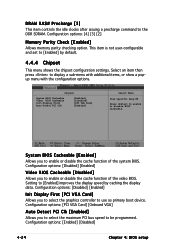
...options: [2] [2.5] [3] Active to CAS# Delay DRAM RAS# Precharge Memory Parity Check [Auto] [By SPD] 3 8 4 4 Disabled Select Menu Item Specific Help Set DRAM Frequency. 4.4.3 Memory Configuration This menu shows the memory configuration settings. Configuration options: [Manual] [By SPD] The items ...only when the Memory Timing Selectable item is set according to the DRAM SPD (Serial Presence Detect). Select [Manual] to allow setting the succeeding memory items to display a pop-up menu with the configuration options. Configuration options: [4] [3] [2] ASUS NCCH-DR 4-23 Select [...
...options: [2] [2.5] [3] Active to CAS# Delay DRAM RAS# Precharge Memory Parity Check [Auto] [By SPD] 3 8 4 4 Disabled Select Menu Item Specific Help Set DRAM Frequency. 4.4.3 Memory Configuration This menu shows the memory configuration settings. Configuration options: [Manual] [By SPD] The items ...only when the Memory Timing Selectable item is set according to the DRAM SPD (Serial Presence Detect). Select [Manual] to allow setting the succeeding memory items to display a pop-up menu with the configuration options. Configuration options: [4] [3] [2] ASUS NCCH-DR 4-23 Select [...
NCCH-DR User Manual English Version
Page 86
Configuration options: [4] [3] [2] Memory Parity Check [Enabled] Allows memory parity checking option. This item is not user-configurable and set to [Enabled] by caching the display data. Configuration options: [Disabled] [Enabled] Init Display First [...
Configuration options: [4] [3] [2] Memory Parity Check [Enabled] Allows memory parity checking option. This item is not user-configurable and set to [Enabled] by caching the display data. Configuration options: [Disabled] [Enabled] Init Display First [...

NCCH-DR User Manual English Version
Page 92
If you choose auto, you cannot select IRQ DMA and memory base address fields, since BIOS IRQ Resources IRQ-3 assigned to IRQ-4 assigned to IRQ-5 assigned to IRQ-7 assigned to IRQ-9 assigned to IRQ-10 assigned ...
If you choose auto, you cannot select IRQ DMA and memory base address fields, since BIOS IRQ Resources IRQ-3 assigned to IRQ-4 assigned to IRQ-5 assigned to IRQ-7 assigned to IRQ-9 assigned to IRQ-10 assigned ...


